Mier products ACE Series User manual

Temperature Controlled Enclosures
Protect your electronics and control their environment!
BW-124-8-ACE
NEMA 4, 24”W x 24”H x 8”D
with an 800 BTU AC unit
ACE Series
Outdoor enclosures with UL Listed
air-conditioners, lters, and thermostats
BW-242410ACE
NEMA 4X, Polycarbonate,
non-metallic enclosure,
24”W x 24”H x 10”D with an
800 BTU AC unit
BW-124ACE
NEMA 4, 24”W x 24”H x 12”D
with a 2000 BTU AC unit
BW-136ACE
NEMA 4, 24”W x 36”H x 12”D
with a 2000 BTU AC unit
BW-RACKACE
NEMA 4, 22”W x 12RU H x 24”D
with 2000 BTU AC unit and an
internal 19” rack
BW-124-8-ACHT
NEMA 4, 24”W x 24”H x 8”D with an
800 BTU AC unit and 150W heater
BW-136ACHT
NEMA 4, 24”W x 36”H x 12”D with a
2000 BTU AC unit and 500W heater
BW-124ACHT
NEMA 4, 24”W x 24”H x 12”D with a
2000 BTU AC unit and 500W heater
ACHT Series
Outdoor enclosures with UL Listed
air-conditioners, heaters, lters, and thermostats
BW-242410ACHT
NEMA 4X, Polycarbonate,
non-metallic enclosure,
24”W x 24”H x 10”D with an
800 BTU AC unit and a
150W heater
Add a “W” at the end of these
part numbers for an optional
window in the door as shown
above and below.
BW-RACKACHT
NEMA 4, 22”W x 12RU H x 24”D
with 2000 BTU AC unit, 500W
heater, and an internal 19” rack
Don’t see the enclosure you need?
Call or e-mail us and we’ll be happy to help!
Protection from Vandals and Mother Nature!
Indoor & Outdoor Electrical Enclosures | Drive-Alert Vehicle Detection & Asset Protection Systems | Custom Fabrication
BW-124-8-ACESS
Stainless steel NEMA 4X
version
BW-124ACESS
Stainless steel NEMA 4X
version
BW-136ACESS
Stainless steel NEMA 4X
version
BW-RACKACESS
Stainless steel NEMA 4X
version
BW-124-8-ACHTSS
Stainless steel NEMA 4X
version
BW-124ACHTSS
Stainless steel NEMA 4X
version
BW-136ACHTSS
Stainless steel NEMA 4X
version
BW-RACKACHTSS
Stainless steel NEMA 4X
version
P
R
O
U
D
L
Y
M
A
D
E
I
N
T
H
E
U
S
A
F
O
R
O
V
E
R
3
0
Y
E
A
R
S
!

ATTENTION: When choosing an enclosure for your application, careful
consideration must be given in determining the heat load and operating
temperature parameters of the electronics mounted within. Also consider
the conditions of the environment where the unit is to be mounted, and the
moisture toleration of the electronics mounted within. Based on these facts,
the need for air-conditioning, humidity control, heat, and/or fans can be
determined as well as the NEMA rating needed. (For example, if the
electronics cannot be exposed to moisture of any kind, a NEMA 3R fan-
ventilated unit would NOT work; you would need at least a NEMA 4 or
NEMA 4X unit.) Mier commonly recommends the highest NEMA rated and
most effective Temperature Controlled units which are the “ACHT” series
enclosures.
Mier’s FC, ACE & ACHT Series enclosures are special order and typically take
2-4 weeks to ship. As they are special order, they are non-returnable/non-
cancellable.
NOTE: To keep NEMA Rating, installers must strictly
follow OEM installation instructions and must properly
install NEMA rated water-tight ttings on all openings.
DO NOT MOUNT enclosures equipped with air-conditioners on walls
of apartments, ofces, condos or homes due to slight vibration from
the AC unit, which might become a nuisance to those who live/work
on the other side of the wall. Mier recommends mounting these units
on concrete pads using vertical struts of angle-iron or poles, or
mounting on walls not common to living/work areas.
Remember: Sealing the outside of pipes and holes made for conduit
is only half the job. Always make the pipe and hole openings inside
the enclosure water/air-tight to prevent condensation, or even mice,
coming up into the enclosure from the ground. It is recommended all
holes be made in the bottom of the enclosure so the entire unit acts as
a moisture shield.
Powder-Coated Steel, Stainless Steel or Polycarbonate: Mier offers all
of these choices in temperature controlled enclosures. ALL of Mier’s
Air-Conditioned and Air-Conditioned with Heater enclosures are
NEMA4 air/dust/water-tight. The Polycarbonate and Stainless models
add the benets of NEMA 4X add even more corrosion protection.
Mier Products’ Temperature Controlled Enclosures
Installation and Warranty Information
Mier’s outdoor enclosures are designed to
provide a degree of protection against rain,
sleet, snow, ice, dirt, and dust.
***** AC/Heater Units Must be kept upright at all times or damage to cooling system may result *****
2000BTU & 800BTU AC Units with compressor coil heater and thermostats with variable controls for both cooling or heating
Power:
Once installed correctly, the power cords for the AC unit and the heater are within the enclosure. Thus, the installer/electrician is responsible for
getting power inside the enclosure. It is up to the installer to cut, and properly install with water-tight ttings, any holes needed to run power within or
run cables out of these enclosures. It is recommended all holes be cut into the bottom of the enclosure so the entire unit acts as a moisture shield.
Both the AC unit and the heater get their power from AC 115V, 60hz. Mier recommends the installer/electrician run power into the box via exible or
rigid conduit, with water-tight ttings both inside and out, to outlet boxes mounted within the enclosure. Note: other voltages available.
Wiring: use #12 AWG standard house wiring to a quad outlet box
Connection: the AC/Heater unit has a standard 3-prong NEMA 5-15P plug and the tamper switch connects to the standard low-voltage alarm circuit.
* Power: 115V, 60hz (other voltages available)
* Amp Draw: 2000 BTU draws 7 amps with initial start-up spike of 17.5 amps.
800 BTU draws 3.8 amps with initial start-up spike of 8.5 amps.
* Dimensions: 2000 BTU unit is 10”W x 20”H x 10”D ---- Weight: 63 lbs
800 BTU unit is 7.5”W x 15.75”H x 7.25”D ---- Weight: 27 lbs
* Mounts: Slips into pre-punched holes on enclosure (Note: install gasket rst)
* Min/Max Temp: -40/131 degrees F (-40/55 degrees C)
500 Watt & 150 Watt Heaters
* Power: 115V, 60hz (other voltages available)
* Amp Draw: 500-watt heater draws 4.5 amps, 150-watt heater draws 1.5 amps
Tamper Switch - Plunger style includes both NC and NO contacts
* Maintenance: ***Clean the air lter every six months minimum*** RP aluminum washable air lters are designed to provide
excellent ltering efciency with a high dust holding capacity and a minimum amount of resistance to air ow. Because they are
constructed entirely of aluminum they are lightweight and easy to service. Optimum lter performance is maintained by recoating
the lters after washing with RP Super Filter Coat adhesive. To achieve maximum performance from your air handling equipment, air
lters should be cleaned on a regular basis. The inlet air lter is located behind the front cover. To access lter, pull ring protruding
from slot in bottom of front cover. The lter may now be cleaned or new lter installed.
Cleaning Instructions:
1. Flush the lter with warm water from the exhaust side to the intake side. DO NOT USE CAUSTICS.
2. After ushing, allow lter to drain. Placing it with a corner down will assure complete drainage.
3. Recoat the lters with RP Super Filter Coat adhesive. When spraying lter do so from both sides for maximum concentration of adhesive.

Depending on the model you purchase, some ACE or ACHT units have less or more cubic volume inside.
• Mier’s “ACHT” and “ACE” models come with a 2000 BTU A/C Unit (aka: T-20s). When installed and functioning properly, it will maintain an
internal preset temperature of (+/- 30F) when the internal heat load is 200 watts. For example the BW-124ACE (enclosure size 24”W x 24”H x
12”D) is capable of maintaining an 800F internal temperature (+/- 30F) up to an outside temperature of 1350F.
• Mier’s “ACHT” models also come with a 500W Heater integrated into the A/C unit. When installed and functioning properly, it will maintain
an internal preset temperature (+/- 30F) when the internal heat load is 200 watts. For example the BW-124ACHT (enclosure size 24”x24”x12”)
maintains a preset temperature (+/- 30F) up to a maximum of up to 600F with an outside temperature of -200F. The BW-136ACHT (enclosure size
24”x36”x12”) maintains a preset temperature (+/- 30F) up to a maximum of up to 600F with an outside temperature of -100F.
• Mier’s “8ACHT” and “8ACE” models, AND Mier’s Polycarbonate enclosure AC models, come with the smaller 800 BTU A/C Unit (aka: T-15).
When installed and functioning properly, it will maintain an internal preset temperature (+/- 30F) when the internal heat load is 100 watts.
For example the BW-1248ACE (enclosure size 24”x24”x8”) is capable of maintaining an 800F internal temperature (+/- 30F) up to an outside
temperature of 1250F.
• Mier’s “8ACHT” models also come with a 150W Heater integrated into the A/C unit. When installed and functioning properly, it will maintain
an internal preset temperature (+/- 30F) when the internal heat load is 100 watts.. For example the BW-1248ACHT (enclosure size 24”x24”x8”)
maintains a preset temperature (+/- 30F) 400F internal temperature down to an outside temperature of -200F.
Mier’s Temperature Controlled Enclosures are completely sealed with no knockouts or holes in the enclosure other than those for mounting the AC
unit. When installed correctly with the AC unit they meet NEMA4 standards and may be used either indoors or outdoors, and provide a degree of
protection to personnel against incidental contact with the enclosed equipment, and they provide a degree of protection for the equipment within
from windblown dust, splashing water, hose-directed water, rain, sleet, snow, ice, and dirt.
• This enclosure is properly installed when the top & bottom mounting ears are ush against the wall or mounting struts, and held securely with
appropriate bolts, and the hinges face to the left after the enclosure has been mounted
• Watertight ttings must be used on all openings created by the installer, including on the inside of the conduit. Mier recommends all conduit entries
and holes be made in the bottom of the enclosures. If the NEMA rating of the ttings are less than the enclosure, the enclosure rating drops to that of
the tting. For instance, an enclosure is NEMA 4, but if an installer uses NEMA 3R ttings the enclosure’s rating must drop to NEMA 3R.
• The door-gasket and AC gasket must remain in place and never be removed.
• The AC/Heater unit must be mounted with the provided gaskets installed between the AC/Heater unit and the enclosure, using the appropriate
pre-cut holes on the enclosure, and strictly following OEM installation guidelines.
• The tamper switch should be mounted on the studs at the top of the enclosure
•If you have ANY questions regarding the installation of these products, call Mier Products at 1-800-473-0213
Mier Products’ Temperature Controlled Enclosures
Installation and Warranty Information
URGENT!
The AC UNIT which
accompanies this enclosure
MUST BE KEPT IN THE
UPRIGHT POSITION
AT ALL TIMES,
and handled with the utmost care
during shipping, storage, installation.
The AC UNIT must be mounted to the
enclosure using the pre-cut holes and
supplied gaskets.
The AC UNIT must be installed in the
upright position, and following OEM
instructions in order to maintain
NEMA rating.
ATTENTION:
WATERTIGHT FITTINGS MUST
BE USED ON ALL OPENINGS!
When installed properly:
* AC Unit is UL/cUL 50 Type 3R, 4, 12,
CE UL le SA6453
* Enclosure meets NEMA4 Standards
* Paint meets NEMA 4, UL-1332
* Gasket meets NEMA 4, UL-50 and
UL-94-HB Flammability Rating
* Tamper Switch is UL Pending
* If your installation is in warmer or cooler exterior environments, of if your internal heat load is greater, or if you are installing in a coastal or
highly corrosive area call Mier Products for advice on special order units
* Mier recommends only installing units with window in shaded areas; as interior temperatures of these units reach 200higher in direct sunlight
than units without windows
* Remember to schedule maintenance of Air-Filters which MUST BE CLEANED PERIODICALLY
* The unit with the MOST COOLING AND HEATING PER CUBIC INCH, and most highly recommended, is the BW-124ACHT
For ON-SITE inspection & repair of A/C units, or A/C Tech Support, call nVent Customer Service at 800-896-2665
AC units needing repair or inspection should be viewed onsite and should not be removed. In the rare case these units would be returned, the
returnee must rst obtain an RMA#, follow the strict shipping and packaging guidelines. The enclosures and AC Units must be shipped on their own
skid, and within the original packaging. REMEMBER: The AC Unit must be kept upright at all times.
P
R
O
U
D
L
Y
M
A
D
E
I
N
T
H
E
U
S
A
F
O
R
O
V
E
R
3
0
Y
E
A
R
S
!

Many of the air-conditioners and combination air-conditioner/heater units have optional Malfunction Switches in them, that are
controlled by the red, yellow, and blue wires that exit the AC unit with the power-cord.
2000 BTU AC Unit Thermostat Instruction and Malfunction-Switch Wiring Information
2
1 3
Malfunction Switch Wiring
Red = Common
Yellow = Normally OpenYellow = Normally Open
Blue = Normally Closed
Internal facing surface
External facing surface
Thermostat:
The “ACHT” Series enclosures are both heated and air-conditioned, so there are two dials for the thermostat on these
units. The “ACE” Series enclosures are air-conditioned, without heaters, so there is only one dial for the thermostat.
Malfunction Switch:
Units with the optional Malfunction Switch have a normally open connection between the red and yellowyellow wires, and a
normally closed connection between the red and blue wires. If a malfunction would occur, the red and yellowyellow wires
will be closed and the blue and red wires will be open.
Maximum electrical ratings for this switch are 13 amps for 120V AC models and 10 amps for the 240V AC models.
The malfunction switch on the air conditioner is a pressure switch. It is plumbed into the high pressure side of the
hermetic system. In a typical application, the malfunction switch is not wired to control any component of the air
conditioner, rather it is an independent switch designed to actuate a customer supplied alarm of some type. There is no
power supplied to the malfunction switch, it requires both a power source and an alarm (light, buzzer, bell, etc.) to be of
any use.
The pressure and temperature are relative in refrigeration circuits. Therefore when the temperature goes up then the
system pressure will go up also. Typically the temperature in the system will go up when the lter is clogged, the
condenser blower is not operating, or the condenser coil is obstructed. The malfunction switch will close the contact
which can then send a signal to the customer supplied alarm device.
The overload on the air conditioner is a bi-metal klixon switch through which the power to the compressor ows. If the
compressor gets too hot, the overload opens the circuit, shutting off the compressor. When the switch cools down again,
it closes the contact and allows the compressor to run again.
Pressure Switch Diagram
Red
Common
Blue - NC
Yellow - NOYellow - NO
P
Thermostat
Location
Thermostat location inside
enclosure after installation
P
R
O
U
D
L
Y
M
A
D
E
I
N
T
H
E
U
S
A
F
O
R
O
V
E
R
3
0
Y
E
A
R
S
!
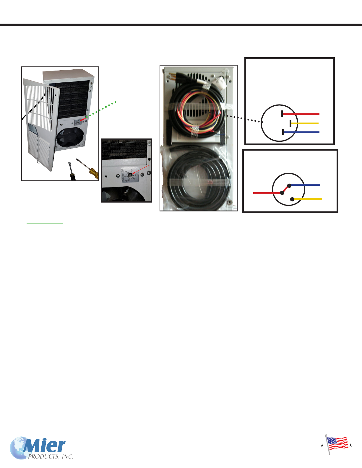
800 BTU AC Unit Thermostat Instruction and Malfunction-Switch Wiring Information
Many of the air-conditioners and combination air-conditioner/heater units have optional Malfunction Switches in them, that are
controlled by the red, yellow, and blue wires that exit the AC unit with the power-cord.
2
1 3
Malfunction Switch Wiring
Red = Common
Yellow = Normally OpenYellow = Normally Open
Blue = Normally Closed
Internal facing surface
Remove FRONT Cover
Thermostat:
The “ACHT” Series enclosures are both heated and air-conditioned, so there are two dials for the thermostat on these
units. The “ACE” Series enclosures are air-conditioned, without heaters, so there is only one dial for the thermostat. The
800 BTU AC unit’s thermostat is set to 75 F/23 C. To change the temperature setting, remove the front face of the unit.
Use a standard screwdriver to adjust thermostat. For cooler temperatures turn clockwise, for warmer temperatures turn
counterclockwise. Setpoint differential is 6 F.
UNITS WITH HEAT
With a dial setting of 75 F, heat will turn on @ 70 F and turn off @ 75 F. Cooling will turn on @ 85 F and turn off at80 F.
There is a 10 F difference between the heater off setpoint and cooling on setpoint to prevent both from operating at the
same time. The dial range of the thermostat is 50-95 F.
Malfunction Switch:
Units with the optional Malfunction Switch have a normally open connection between the red and yellowyellow wires, and a
normally closed connection between the red and blue wires. If a malfunction would occur, the red and yellowyellow wires
will be closed and the blue and red wires will be open.
Maximum electrical ratings for this switch are 13 amps for 120V AC models and 10 amps for the 240V AC models.
The malfunction switch on the air conditioner is a pressure switch. It is plumbed into the high pressure side of the
hermetic system. In a typical application, the malfunction switch is not wired to control any component of the air
conditioner, rather it is an independent switch designed to actuate a customer supplied alarm of some type. There is no
power supplied to the malfunction switch, it requires both a power source and an alarm (light, buzzer, bell, etc.) to be of
any use.
The pressure and temperature are relative in refrigeration circuits. Therefore when the temperature goes up then the
system pressure will go up also. Typically the temperature in the system will go up when the lter is clogged, the
condenser blower is not operating, or the condenser coil is obstructed. The malfunction switch will close the contact
which can then send a signal to the customer supplied alarm device.
The overload on the air conditioner is a bi-metal klixon switch through which the power to the compressor ows. If the
compressor gets too hot, the overload opens the circuit, shutting off the compressor. When the switch cools down again,
it closes the contact and allows the compressor to run again.
Pressure Switch Diagram
Red
Common
Blue - NC
Yellow - NOYellow - NO
P
Thermostat
Location
Thermostat Close Up

Pole Mount Kits
for 2 inch to 5 inch poles (see next page for larger poles)
ATTENTION: THERE IS NO NEED TO DRILL HOLES INTO THE ENCLOSURES TO MOUNT THE
POLE-MOUNT KITS. PLEASE SEE INSTRUCTIONS BELOW.
• For poles that are 2” in diameter up to 5”, our Pole-Mount Kits use two (2) rails
across the top and bottom of the enclosure and t between the enclosure and the pole,
and four (4) pole-brackets that go around the pole (two on bottom and two on top)
which are tightened down for a secure t. (see next page for 6” to 12” poles)
Part numbers for these kits are the BW-24PM2 (2” pole), BW-24PM3 (3” pole)
and BW-24PM4 (4” - 5” poles)
Example of a
Pole-Mount Kits for
2” to 5”
diameter poles
Mier Recommends using at least two people to pole-mount
heavy enclosures, and preforming steps 1-2 PRIOR to going to
job site.
1) Attach the two (2) rails to the enclosure by placing them at
against the Mounting Brackets on top and bottom of the
enclosure, corresponding to the mounting holes. Then place the
3/8 x 16 Bolts through the Rails and the holes in the
enclosure Mounting Brackets. Secure with the 3/8” Washers on
the outside and 3/8 x 16 Flange-Nuts on the inside.
2) Twist and insert the four (4) pole-brackets into the two rails.
Two of these brackets go in the top rail, and two go in the
bottom rail with the curved sections facing inwards towards
each other to wrap around the pole (see photo):
3) Wrap the pole-brackets around the pole, insert the
attachment bolts, secure and tighten with the lock-nuts.
12
2
1
3
3
These pole-mount kits are used with the following Mier Products Enclosures:
BW-1248BP, BW-1248FC, BW-1248ACE, BW-1248ACHT, BW-124BP, BW-124FC,
BW-124ACE, BW-124ACHT, BW-136BP, BW-136FC, BW-136ACE, BW-136ACHT,
BW-RACKACE and BW-RACKACHT

Pole Mount Kits
for 6 inch to 12 inch poles (see previous page for smaller poles)
P
R
O
U
D
L
Y
M
A
D
E
I
N
T
H
E
U
S
A
F
O
R
O
V
E
R
3
0
Y
E
A
R
S
!
ATTENTION: THERE IS NO NEED TO DRILL HOLES INTO THE ENCLOSURES TO MOUNT THE
POLE-MOUNT KITS. PLEASE SEE INSTRUCTIONS BELOW.
• For poles that are 6” in diameter to 12”, our Pole-Mount Kits use two (2) heavy-duty
adjustable bands which t inside the rails across the top and bottom of the enclosure
and t between the enclosure and the pole as pictured on the left and below.
Part numbers for these kits are the BW-24PM6 (6” to 8” poles), BW-24PM8 (8” to 10”
poles) and BW-24PM12 (10” to 12” poles)
Example of a
Pole-Mount Kits for
6” to 12”
diameter poles
Mier Recommends using at least two people to pole-mount
heavy enclosures, and performing steps 1-4 PRIOR to going to
job site.
1) Mark the center point of each Mounting Rails (A).
2) Slide the Adjustable Band Guides inside both Mounting
Rails, and center them to the point marked on step 1 (B).
3) Place the 1/4” x 20 Screws and 1/4” Washers on the outside
of the Mounting Rails, run the bolts through the Mounting Rails
and Adjustable Band Guides, and secure with the 1/4” x 20
locknuts on the inside (C and B).
4) Insert the two (2) Heavy-Duty Adjustable Bands into the
two (2) Adjustable Band Guides inside the Mounting Rails.
The bands should curve outwards, away from the inside of the
Mounting Rails. One (1) of these Heavy-Duty Adjustable Bands
goes in each of the Adjustable Band Guides assembled inside
each of the Mounting Rails (D).
5) Attach the two (2) assembled Pole-Mount Rails onto the two
(2) Mounting Lips of the Enclosure using the four 3/8” x 16
Carriage Bolts entering through the inside of the Mounting Rail,
use TWO (2) of the eight 3/8” EXTRA THICK Washers ON EACH
bolt between the rail and the enclosure lip for proper spacing,
then use the 3/8” Standard Washers on the outside of the Enclo-
sure Lip with the 3/8” ange-nuts (E).
6) Wrap the bands around the pole and use a power driver with
a straight blade screw-driver, or a 3/8” socket tting, to tighten
the bands securely around the pole (F). F
C
D
A
E
B
These pole-mount kits are used with the following Mier Products Enclosures:
BW-1248BP, BW-1248FC, BW-1248ACE, BW-1248ACHT, BW-124BP, BW-124FC,
BW-124ACE, BW-124ACHT, BW-136BP, BW-136FC, BW-136ACE, BW-136ACHT,
BW-RACKACE and BW-RACKACHT

Mounted inside the gate-
house at a gated community
Using metal tubing or angle-
iron and a concrete slab
Along a gate using metal
tubing to run wiring from
one enclosure to another
Wall-mount
Using conduit and
angle-iron
Rack Enclosure mounted
on a wall
Installer made mounting
surface
Pole-Mount Kits
available for enclosures
to be mounted on 4” to
14” poles. Call Mier and
specify the enclosure you
want to use, and the pole
size, for help choosing the
correct pole-mount kit.
NOTE: Do Not Mount On Apartment/Condo/Ofce Walls
Home and ofce AC units are mounted a few feet away from a home or on
the roof of an ofce building in order to avoid vibration noise from
becoming a nuisance to those who live/work within. For that same reason,
Mier recommends installers mount our temperature-controlled enclosures
on concrete slabs with angle-iron or poles as pictured, or on walls that are
not common to living or ofce space.
Our engineers recommend the following options around RGS ttings in holes installers might cut into the enclosures, in order to keep NEMA ratings:
• If not using conduit or ex-cable, and running your cords directly into the enclosure, we recommend drilling your holes in the bottom of the
enclosure and using a Heyco tting appropriate for your specic cord size, and able to t in our 3/16” enclosure wall thickness.
• If you are using conduit or ex-cable, we recommend drilling your holes in the bottom of the enclosure and using an appropriate tting such as:
• SealCon DS21AA-BK = ¾” Liquid-Tight Conduit Fitting with DOUBLE Lock - http://www.sealconusa.com/conduit/product/double-seal.html
• SealCon ST21NA-BK = ¾” Liquid-Tight Conduit Fitting with SINGLE Lock - http://www.sealconusa.com/conduit/product/condsttwist-npt.html
• McMaster Carr 7119K13 = ¾” Liquid-Tight Conduit Fitting/Heavy-Duty - http://www.mcmaster.com/#7119k13/=vg864m
Remember: sealing the outside
of holes used for conduit
coming up from the ground is
only half of the job. You must
also make the inside of the
opening from the
conudit water/air-tight to
prevent ground condensation
and even mice from coming up
into the enclosure!
Customer Shared Mounting Examples and Notes
Make sure you properly ground the enclosure, especially if mounting to a wall or wooden posts. If you’re not sure how to do this,
consult a certied electrician or contact the manufacturer.
NOTE: all conduit and holes
are in the bottom of the
enclosure. This allows the
entire unit to act as a shield
against rain, sleet, snow,
moisture, etc.

ENCLOSURE WARRANTY:
Mier Products, Inc.’s Limited Warranty Program, for Standard Line or Custom Enclosures and Parts, protects the original owner for 30 days from the
date of purchase against defects in original parts or workmanship. Mier Products, Inc. agrees to repair or replace parts (Mier’s option) that are deemed
defective by our Quality Control Team, without charge for parts or labor, if the defective unit is returned prepaid to Mier Products, Inc., Kokomo, IN,
within the 30-day period.
Enclosures and fabricated parts are not products containing complicated technology or electronics, so close inspection at the time of receipt by the
customer will quickly determine product quality. Thus, Mier Products, Inc. recommends inspection of enclosures/parts immediately upon receipt and
contacting Mier Products, Inc. if quality issues arise.
Mier Products, Inc. does not assume responsibility for claims or damages caused by improper installation or use of these products, accessories, and/
or products connected to or stored within them. Mier Products, Inc. does not assume responsibility for damages to these products or their accessories
due to shipping damage or damage occurring while in a customer’s warehouse and/or possession. These products and any accessories (including but
not limited to air conditioning units, heaters, fans, lters, locks, latches, tamper switches, removable panels) must be shipped, handled, stored, and
installed with strict adherence to OEM installation instructions.
This warranty constitutes the entire warranty with respect to Mier’s Drive-Alert Models and Accessories and IS IN LIEU OF ALL
OTHERS, EXPRESSED OR IMPLIED, INCLUDING ANY WARRANTY OR MERCHANTABILITY AND WARRANTY OF FITNESS FOR A PARTICULAR
PURPOSE AND IN NO EVENT IS MIER PRODUCTS, INC., OR IT’S DISTRIBUTOR, DEALER, OR OEM PARTNERS, RESPONSIBLE FOR ANY CONSE-
QUENTIAL DAMAGES OF ANY NATURE WHATSOEVER.
Any warranty OR sales questions should be directed to Mier Products at 800-473-0213, or via e-mail to [email protected]
Any repair work not covered by this Warranty is available for a nominal charge.
AIR-CONDITIONER, HEAT EXCHANGER, AND FILTER WARRANTY
Mier Products exclusively uses nVent (Mier’s business partner for the heating and cooling systems used in Mier’s Temperature Controlled Enclosures)
air-conditioners and air-conditioners with integrated heating units. The following warranty information was taken from nVent’s warranty policy (10-1008-196
rev 5) for your information. All AC and Heater units come with a nVent instruction manual with warranty infomation included. That information, shipped
with each nVent Thermal unit, supercedes what is written here:
Synopsis of nVent Thermal Warranty
Please note: Warranty effective at time of shipment.
nVent warrants that all material and workmanship are free of defects in quality which impair the usefulness of the air conditioner or heat exchanger for a
period of ve (5) years for non-operating parts, except for the lter; and for one (1) year for everything else when installed and operated under the following
conditions:
A. Maximum voltage variation no greater than plus or minus 10% of nameplate nominal rating.
B. Maximum frequency variation no greater than plus or minus 3 Hz. of nameplate nominal rating.
C. Must not exceed minimum and maximum stated temperatures on the nameplate.
D. Not to exceed (BTU/Hr.) rating, including any heat sink, as indicated on the nameplate.
E. The unit must not be restarted for a period of one (1) minute after intentional or accidental shut-off.
(This does not apply to heat exchanger or lter fan.)
nVent warrants that all material and workmanship are free of defects in quality which impair the usefulness of the lter fan package and all custom air condi-
tioners and heat exchangers for a period of one (1) year, except for the lter, when installed and operated under conditions A, B, C and D above.
Not covered in this warranty is damage to the air conditioner or heat exchanger due to the introduction of other than the nameplate-designated refrigerant.
Operation of any nVent product that has not been designed with proper protective coatings and/or options and is in an abnormal or corrosive environment
voids the warranty.
***Prolonged operation with dirty lters also voids the warranty***
Should any part prove defective within the above warranty period, the customer may choose to return the defective product that is under warranty to nVent
for repair at no charge or the customer has the option to repair the defective products at his own expense and nVent will supply repair parts at no charge
providing the defective part is returned and found to have failed under warranty. Parts supplied as warranty replacement parts will assume the balance of the
warranty on the part returned for warranty consideration.
Please be advised: According to the Federal Register, no person maintaining, servicing, repairing, or disposing of appliances may knowingly vent or otherwise
release into the environment any class I or class II substance used as refrigerant.
nVent assumes no liability beyond the repair or replacement of its own product. Customer modication of nVent products voids the warranty.
The purchaser assumes the responsibility of grounding the unit and installing it in accordance with local electrical and safety codes, as well as the National
Electric Code (NEC) and OSHA.
Warranty Information
P
R
O
U
D
L
Y
M
A
D
E
I
N
T
H
E
U
S
A
F
O
R
O
V
E
R
3
0
Y
E
A
R
S
!
This manual suits for next models
19
Table of contents
Other Mier products Enclosure manuals


Popular Enclosure manuals by other brands

Natec
Natec OYSTER PRO user manual

Thermaltake
Thermaltake Versa Series user manual

Akasa
Akasa integral HDD external enclosure for data-storage mobility with LAN... user manual

StarTech.com
StarTech.com SAT3510BU3 instruction manual

Apollo Enclosures
Apollo Enclosures ELITE Series installation guide

AudioBahn
AudioBahn ABASS10 operating instructions


