4
The MultiFeeder can be used together with a SIGMA2
Compact in robot installations and other cases, where
1 or 2 extra wirefeeders are required. The MultiFeeder
can be configured with various torches, remote
interface and Mig Manager® interface.
1. The MultiFeeder communicates with the SIGMA2
via a CAN-interface and is connected on the rear
panel of the SIGMA2 via a cable, which can be up
to 15 meters.
2. The documentations for the MultiFeeder consists
of the following:
Functional description incl. configuration.
Mechanical drawing
Functional description
When using 2 MultiFeeders on the same SIGMA2, the
MultiFeeders must be configured as no. 1 and no. 2.
This is done by placing a jumper on the PCB
71613658 as shown in fig. 1.
Functions
The main functions of MultiFeeder is like a standard
SIGMA2 wirefeeder without any userinterface/panel
and can be used with or without robotinterface
connected to the SIGMA2 Compact. The internal
wirefeeder in the SIGMA2 Compact is still available,
when MultiFeeders are connected to the SIGMA2.
Using the MultiFeeders without robotinterface:
The MultiFeeder as well as the internal wirefeeder can
be triggered from the connected torch. When the
MultiFeeder is active (LED-lamp on front is ON),
welding is started immediately. When the MultiFeeder
is not active (LED-lamp on front is OFF), the trigger
will make a programshift and activate the MultiFeeder
without starting welding. Welding is started when the
trigger is activated. The internal wirefeeder in the
SIGMA2 is active, when none of the MultiFeeders is
active.
Pressing the wire inching-button (on front) will start
wire inching immediately, if welding is not started or in
progress. The wire speed can be adjusted on the
SIGMA2 userinterface.
The gastest function is performed only on the active
Multifeeder/wirefeeder by pressing the Gastest-button
on the SIGMA2.
Using the MultiFeeders with robotinterface
The active MultiFeeder (indicated by LED-lamp on
front) is selected from the robotinterface. If the robot-
interface is configured for internal program select,
selecting/activating a MultiFeeder/wirefeeder will
perform a programshift to the program last used with
the specific MultiFeeder/wirefeeder. If the robot-
interface is configured for external program select,
selecting/activating a MultiFeeder/wirefeeder will not
result in a programshift. The SIGMA2 remembers the
welding program last used for each MultiFeeder/
wirefeeder on power-down.
The MultiFeeder can be triggered only from the
robotinterface, and welding is started immediately.
Pressing the wire inching-button (on front) will start
wire inching immediately, if welding is not started or in
progress. Wire inching can also be performed on the
active MultiFeeder/wirefeeder by activating the wire
inching-input on the robotinterface. The wire inching
speed can be adjusted from the robotinterface, but if
this wire inching speed is set to a value below
0.5 m/min, the default value for wire inching speed
8.0 m/min is used.
The gastest function is performed only on the active
Multifeeder/wirefeeder by either activating Gastest-
input on the robotinterface or by pressing the Gastest-
button on the SIGMA2.
The LED-lamp on the front of the MultiFeeder is ON,
when this Multi-Feeder is activated. When none of the
MultiFeeders is active, the internal wirefeeder in the
SIGMA2 is active.
Configuration
MIGATRONIC disclaims all responsibility for damaged
cables and other damages related to welding with
under sized welding torch and welding cables
measured by welding specifications e.g. in relation to
permissible load.
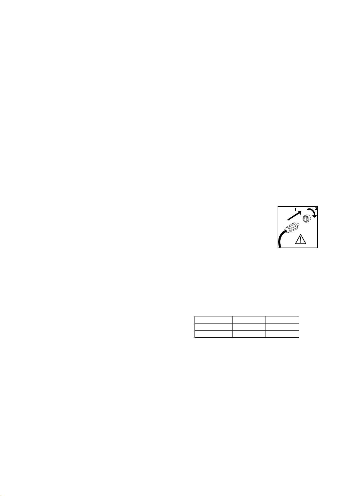
Important!
In order to avoid destruction of plugs
and cables, good electric contact is
required when connecting earth
cables and intermediary cables to the
machine.
Accessories
The MultiFeeder can be equipped with various
standard torches, Mig Manager® and SIGMA2 remote
control
Intermediary cables
Intermediary cables is delivered in lengths of 8m (size
70mm² or 95mm²)
Order no. Length Size
74325964 8m 70mm²
74325965 8m 95mm²