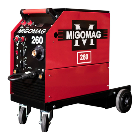
Migomag 260PS User manual

1
OPERATING
INSTRUCTIONS FOR
MIGOMAG
SEPARATE WIRE FEEDER
WELDING MACHINES
260PS
(ITEM # AAM260PS)
350PS
(ITEM # AAM350PS)
400PS
(ITEM # AAM400PS)

2
INDEX
FRONT COVER ...............................................................................1
INDEX...............................................................................................2
INTRODUCTION..............................................................................3
ASSEMBLY INSTRUCTIONS .........................................................3
SETTING UP FOR OPERATION ....................................................3
MACHINE CONTROLS /CONNECTIONS................................. 4
SHIELDING GAS.............................................................................4
WORK ENVIRONMENT ............................................................. 4
OPERATION ....................................................................................5
SETTING UP GUN FOR WELDING ALUMINIUM .........................5
WELDING HINTS ....................................................................... 6
WELDING FAULTS .........................................................................7
SAFETY............................................................................................8-9
SHIELDING GAS TABLE ................................................................10
MACHINE BREAKDOWN & PARTS DESCRIPTION .....................11-13
WARRANTY.....................................................................................14
CONTACT DETAILS........................................................................15

3
INTRODUCTION
Afew minutes spentreadingabout yournewMIGOMAG
MIG welding machine will enable you to operate your
machineefficientlyandbenefitfromitsmanyfeatures.
ASSEMBLY INSTRUCTIONS
1.
Fit the Heavy-Duty rubber tyred castor wheels and
rearwheels tothe chassisof the welder.Ensurethe
smalllip of thecylinder tray faces the rear to enable
easyliftingofthegascylinder.
2.
Connect the wire feed unit to the power source by
fitting the gas hose, control cable and power cable to
terminals as shown (FIG 3)
Note: See welding hints for running solid or
gasless wires.
3.
Install the cable liner to the welding gun cable as
follows:
i.
Laythetorchandlineroutstraight.
ii.
Checkthatthelinerhasnokinksinit.
iii.
Removethelinerpositioningnutatthemachine end
ofthetorch.
iv.
Removenozzle,tipandtipholderifapplicable.
v.
Gently feed the liner down through the bicox cable,
from the machine end of torch, taking specialcare
not tokinkit in theprocess. Once the liner reaches
the back of the swan neck it may be necessary to
gently twist it through.
vi.
With the liner now fully home, replace the liner
positioning nut. (Do not over tension).At the front
end of the torch there will now be approx.300mm
(12inches) of linerprotruding fromthe swanneck.
vii.
Gently stretch the liner a further 4mm (3/16 inch)
and cut at the tip of the neck with a sharp pair of
cutters. Thelinerwillnowspringbackintoswanneck
by 4mm.
viii.
Refit tip holder, tip and nozzle.
SETTING UP FOR OPERATION
Fit Torch To Machine
Carefully align gas connection tube and trigger connection
pins with central adaptor. Push in and tighten the lock nut.
Open the wire feed pressure are (Fig. 1) above the feed roll.
Feed the roll to suit the diameter of wire to be used.
Feed Roll Changing (if required)
Remove the feed roll retaining knob. Pull off feed roll.
When replacing the feed roll, note the wire size which is
stamped on the side face of the roll. The required size
must face inwards when the roll is refitted. Ensure that
the Woodruff Keyisnotlost. Fit the feed roll and refit the
retaining knob using thumb and forefinger.
Don't over
tighten
.
Fit The Reel Of Welding Wire
Remove the red hand nut from hub.
Place the reel of
wire on hub so that the wire will be drawn off from the
bottom.
Ensurethat the pinon thehublocatesinthehole
in the sideofthewire reelspoolreel.
Replace red hand
nut.
Overrun Adjustment
Tighten or unscrew the hub tension nut in the center of
the hub reel assembly unit sufficient hub friction is
achieved to prevent overrun. This adjustment should
be done with a full spool of wire at maximum wire feed
speed. Do not over tighten.
Feed Roll Adjustment
Release the wire end from reel and cut offthe bent wire
end, takingcare that thewiredoes notunwind. Remove
the nozzle and contact tip from the welding gun.
Straighten about 20cm of the wire and make sure that
the end is as blunt as possible (file off if necessary). A
sharp end could damage the cable linerandthecontact
tip of the welding torch.
Ensure the wire is placed
correctly on to the feed rolls.
FIGURE 1.
Feed Roll Alignment
FIGURE 2.
To adjust, release the three screws holding motor drive
assembly and lower or raise to achieve correct alignment
(Fig.2).
Thread some wire through the feed rolls into the guide
tube and liner of the welding cable.
Close the wire feed
pressure arm.
The pressure adjustment of the feed rolls
must be set so that the wire is fed evenly into the liner and
light restriction of the wire can be made without the feed
rollsslipping.
Note: Excessive pressure will cause flattening of
the wire, loosening of the wire coating and
undue wear of the rolls.
Switchonmachineandsetthewirefeedspeeddial onalow
setting.
Keep the cable of the welding torch straight and
press the switch on the torch until the wire end comes out
of the gooseneck.
Replace the contact tip and nozzle.
Earth Connection
The earth connection from the welder should at all times be
made directly on to the piece to be welded. The contact
between the earth and the job should be as large and as flat
aspossible, and all rust and paint
.
Connect the earth cable to the earth connection socket (5).
The MIGOMAG 260, 350 & 400
have two connection
sockets;(5.i) is for very light welding applications and (5.ii) is
for heavier welding applications. The MIGOMAG 400PF4CE
has three connection sockets.
Gas Flowmeter/Regulator
To fit the Flowmeter/Regulator to the gas cylinder, first open
the cylinder valve slightly to remove any dirt from the valve
socket and close valve.
Fit the Regulator to the valve socket
and hand tighten nut with a suitable size spanner.
Back off the pressure regulator adjusting knob by
turning anticlockwise.
Fithosetailandnuttothegashoseandholdcaptivewith the
hose clamp, (found in the wire feed compartment of the
machine adjacent to the wirefeed rolls).
Connect the gas
hosetotheregulator,openthecylinder valveandadjustgas
flowrate(seeShieldingGasforflow rates).
Note
: Plug top must be fitted by a qualified electrician.

4
MACHINE CONTROLS/ CONNECTIONS
1.
ON/OFFSwitch
With this switch in the ON position, power is
applied to the fan and control circuits.
WARNING:
This switch does notisolate the unit
from the mainselectricalsupply
.
2.
t1 -'ON' TIME CONTROL for SPOT welding
and
STITCH 'ON’ time
3.
t2 - 'OFF' TIME CONTROL for STITCH 'OFF'
time.M260,M350,M400only
4.
WIRE FEEDSPEED (CurrentControl)
5.
NEGATIVECONNECTION
i.
InductanceSocket-Low
ii.
Inductance Socket MedHigh
iii.
Inductance
Socket
High
6.
VOLTAGESELECTORSWITCH Fine
7.
CENTRALADAPTOR
8.
VOLTAGESELECTORSWITCH Coarse
9.
POSITIVECONNECTION
10.
CONTROL CABLE SOCKET
11.
GAS HOSE CONNECTION NIPPLE
12.
GAS PURGE BUTTON (PF4 only)
13.
TRIGGER LATCHING SWITCH (PF4 only)
14.
WIRE INCHING BUTTON (PF4 only)
Welding Voltage Adjustment
MIGOMAG 260PF3
The welding voltage is regulated by a 2-position switch
for course control and an 8-position switch for fine
control, a total of 16. Position (8) and (6) on the front
panel.
MIGOMAG 350PF3
The welding voltage is regulated by a 3-position switch
for course control and an 8-position switch for fine
control, a total of 24. Position (8) and (6) on the front
panel.
MIGOMAG 400PF3
The welding voltage isregulated by a 6-position switch
forcoursecontrolanda6-positionswitchforfinecontrol, a
totalof36. Position(8)and (6)onthe frontpanel.
WARNING: If the welding voltage is set too high,
the weld can burn through light gauge sheet
metal. In this case,the voltage should be reduced.
If set too low, the weld will have little penetration
andwilljust "siton" theplate
FIGURE 3.
Wire Feed Speed
The wire feed speed is regulated from 0-18mm/min by the
potentiometer dial (4) above the voltage switch.
It is most
important to select the wire feed speed in relation to the
voltage setting. The correct wire feed speed/voltage
setting is recognisable by:-
1.
A continuous regular 'crackling' sound when
welding, the characteristics of dip transfer of short-
arcwelding method normally used bysmall medium
sizedMIG/MAGwelders.
2. A correct shape weld bead not too high, or low, with
correct fusion along the edge of the weld without
undercut in the heat-affected zone.
Welding Mode Switch/Timer
Controls 't1'and't2'arefittedtoallmodels. Both 't1' and 't2'
controls are used to control the welder ON/OFF times
during stitch welding and 't1' is used alonetocontrolspot
weldingtime(ON)
For normal continuous (trigger controlled) welding,
ensure both 't1' and 't2' controls are turned fully
anticlockwise to the OFF positions.
Protection Device
Protectionagainsttheeffectsofoverheatingisprovided by
thermal protection devices mounted on the transformer
assemblyandrectifier.
In the event of overheating, power to the unit is
interrupted.
The protection device automatically resets
oncetheunit cools.
SHIELDING GAS
The gas provides a shield over the weld pool to prevent
contamination from the surrounding air. The shield gas
also contributes to arc stability, weld strength, and
appearance, so care should be taken to ensure that the
correct gas type/mixture is selected for the metal being
welded.
(Refer Table page 9).
The gas flow rate, adjusted by the regulator, increases
with variations in welding gun nozzle diameter,and should
be15litresperminutefortheMB24weldinggun to 25 litres
per minute for the MB36 welding gun with cylindrical
nozzle.
Excessive gas flow rates should be avoided as they are
wasteful, and in some instances, can cause weld porosity.
WORK ENVIRONMENT
The machine should be used indoors away from strong
draughts whichmaycause gasdissipation.
If the machine is to be covered, the natural cooling air
circulation must not be interrupted.
Before commencing
welding, clear area of flammable materials.
OPERATION
Continuous Welding
Ensure that both timer switches 't1' and 't2' are in the
'OFF' position.
Set the voltage and wire feed controls to
positions suitable for welding the thickness of the material
being welded.
Welding current varies in direct relationship to wire feed
speed.
For low welding current output, the wire feed
speed control should be set at the low end of the wire feed
speed scale.
Turning the wire feed speed control knob clockwise, will
result in increased wire feed speed and welding current.
Welding voltage is adjusted to match the wire feed speed
(weldingcurrent).
For welding in the low current range, set
the voltage switchtopositionnumber(1)(number1onboth
voltage switches for MIGOMAG 260+300+350+400).
These MIGOMAG machines have two voltage selection
switches, a coarse control (8) and fine voltage selection (6).

5
Progressively select higher voltage positions with increases
in wire speed.
Low wire feed speed settings for a given voltage will
causealargeballtoformontheendoftheweldingwire and
causeexcessivespatter.
High wire feed speed settings for
a given voltage will cause wire stubbing.
Positionthetorch
over the seam to be welded with the nozzleapproximately
70°totheworksurface.
The nozzle to work distance should
be approximately 10mm.
WARN BYSTANDERS TO SHIELD THEIR EYES.
Lower your helmet and press the welding gun trigger
switch to initiate an arc.
As the weld isdeposited,pushthe
torch from a right to left direction,slowlyalongtheseamat
a constant speed. Using the wire feed speed control,
adjust for a 'crisp' soundingarc.
Spot Welding
MIG spot welding is made fromone side of the sheets
placed one upon another so that the high welding current
penetrates through the upper sheet(max.1.5mm) and
also a part ofthe lower sheet.
A circular spot is produced
each time the torch trigger is pressed. The spotweldtime
't1'canbevaried.
Select'spot'weldingbyturningswitch't1"
only.
Fit a spot-welding nozzle to the torch.
See GUN PARTS LIST.
Set voltage and wire feed speed controls to near max.
settings and carry out test welds on scrap materials as
follows:
Position the legs of spot-welding nozzle over weld
position and depress torch trigger switch. At the
termination of the weld, check for weld penetration (small
dimple showing on underside of weld), and adjust spot
weldtimeforbestresults.
When welding sheets of unequal
thickness, the thinner sheet must be on top. Thicker
sheets can be welded together by drillinga hole inthe top
sheet anddirecting thewireinto hole-thisis knownas'plug
welding'.
Spot welding requires ONLY LIGHT PRESSURE;
the sheets are pressed against each other with the legs of
the welding nozzle.
Switch Welding All Models
The wire feed output is switched on and off repeatedly.
This produces a lower heat input which is particularly
advantageous when welding thin or poor-quality materials
aswellasbridginggaps.
Select 'stitch' welding by turning 't1'and 't2'controls to the
halfway setting. Vary time to obtain best results. Theydo
nothave tobeequal.
't1' controls the welding or working cycle.
't2' controls the
pause cycle between welding.
Note: The trigger on the gun must be kept depressed during
bothcycles.
Welding occurs during the working (ON) cycle. During the
pause cycle, the wire feed STOPS, and the arc will
extinguish.
During the pause cycle the moltenpool will cooldown. The
arc will ignite again automatically at the beginning of the
following working cycle when the filler wire makes contact
with the molten pool.
The welding current is automatically switched on and off
and the shielding gas supply will remain on during the
pause cycle.
Note: Spot welding and stitch welding of aluminium is
not possible.
SETTING UP GUN FOR ALUMINIUM WELDING
The Welding Gun
Remove the liner positioner nut from the adaptor block at the
wire feed end of the gun cable. Remove the gas nozzle,
contact tip holder, gas diffuser/ contact tip from the welding
torch and remove existing liner if fitted.
Carefully push the Teflon liner with brass neck liner attached,
through the gun cable until the end of the liner protrudes from
the swan neck.
Adjust the contact tip holder, gas diffuser/ contact tip and gently
push the liner to seat it into the back of the contact tip holder/
contact tip. Replace the gas nozzle.
At the adaptor block end of the gun cable, slide the brass nipple
and “O” ring over the liner until they are located om the recess
in the adaptor block and replace the liner retaining nut.
DO NOT CUT THE TEFLON LINER YET!!
FIGURE 4.
The Welding Machine
With a pair of long-nosed pliers, remove the steel inlet
guide tube from the central adaptor on the front face of the
weldingmachine.
With the Teflon liner still protruding from the adaptor
block
feed the liner through the inlet of the central adaptor until
the adaptor block is butted against the central adaptor.
Fastenintopositionwithadaptorblock locknut.
Cutthelinerintheshape ofa'V',usingasharpknifeso that
it butts up to the feed rollers as pictured. (FIG.4.) Remove
the welding gun from the machine and cut the brass
support tube so that it is 3mm shorter than the protruding
Teflonliner.
Slide the brass support tube over the liner and enter the
Teflonlinerwithbrasssupporttubefittedintotheinletin the
central adaptor. Feed through until the adaptor block is
buttedagainstthecentraladaptorandtightenthelock nut.
Replace the wire hub tension by backing off the nutin the
centre ofthehubuntilthenutispositioned attheendof the
stud.
After confirming the wire feed roll is the correct size for the
aluminium wire being used, and that the wire is fed through
the gun cable, back off the wire feed roll pressure screw until
the feed roll no longer feeds the wire and re-tighten
approximately 2turns. Toomuchpressure willdeform the soft
aluminium wire and cause the wire to jambin thecontacttip.
Note: To help prevent wire deformation
‘U' groove
feed roller is a better alternative than a 'V'
groovefeedroller.
Contact Tip
Aluminium welding requires a contact tip with greater
clearance than that used for steel. Special clearance contact
tips are available for welding aluminium and are designed
withAsuffix.e.g.0.9A,1.2A.
PARTS LIST
Part No. Description
1260005 Teflon Liner 1.0mm
1260021 Teflon Liner 1.2mm
1290461 Brass Support Tube for Teflon Liner
1310001 Nipple for Teflon Liner
86003033 Drive Roll 0.9/1.0-1.2mm AI (195 230 260
300)
86003066 Drive Roll 0.9/1.0-1.2mm AI (350 400)
1410004 Contact Tip 0.9mm Aluminium
1410006 Contact Tip 1.0mm Aluminium
1410010 Contact Tip 1.2mm Aluminium
86007001 Brass Neck Liner

6
WELDING HINTS
Welding with Solid Wires (Steel, Aluminium &
Stainless Steel)
The flexible welding cable extending from the wire feed
unit should be plugged in to the Positive socket and the
earthleadpluggedintooneoftheNegativesockets.
Gasless Wire Welding (Flux Cored)
For gasless welding wire requiring reverse polarity, the
flexible welding cable extending from the wire feed unit
should be plugged in to the Negative socket, and the
earthlead intothePositivesocket.
Gasless welding wire requires lower wire feed speeds and
voltage when compared to solid wires.
To ensure a positive wire feed, knurled feed rolls
appropriate tothe wiresizebeingusedshould be fittedin
placeofsmoothfeedrolls.
Aluminium Welding
Select a voltage setting approx. halfway through thelow
range on your machine (e.g. 1+6 of 12, or2+4 of24).Set
thewirefeedspeedtoapprox.10andthegasflowmeter to
approx.20-25litresper minutewhenwelding.
Remove oxide coating from weldments with a stainless-
steelwirebrush. Initiate arc andliftthe torch nozzle away
fromtheweldpooluntil thenozzle/welddistance is12-15
times the diameter of the wire (e.g. 11-14mm for 0.9mm
wire).
Direction of travel should be from right to left by pushing
thegun.
ALWAYS TEST SETTINGS ON A SCRAP PIECE OF
MATERIAL FIRST.
Stainless Steel Welding
Always use a clearance size liner (e.g. 1.2mm liner for
0.9mm wire). Voltage and wire feed settings will be
similarto those usedforwelding mild steel. However,the
differentgaswillincreasethearctemperature.
Set the gas flow meter to approx. 20 litres per minute.
Ensure when welding that the torch nozzle is lifted away
from the weldpool until the nozzle/weld pool distance is
12-15 times the diameter of the wire. A clearance size
contact tip may be necessary in some situations of high
torchheat. (e.g. 0.9A mmtip for 0.9mmwire,or 1.2Amm
tipfor1.2mmwire).

7
WELDING FAULTS
FAULT
POSSIBLE CAUSE & REMEDY
Weld deposit 'stringy' and incomplete
1. Torch moved over work piece too quickly
2. Gas mixture incorrect
Weld deposit too thick
1. Torch moved over work piece too slowly
2. Welding voltage too low
Arc unstable, excessive spatter and weld porosity
1. Torch held too far from the workpiece
2. Rust, grease or paint on workpiece
3. Insufficient shielding gas: check gas contents gauge,
regulator setting and operation of gas valve
Wire repeatedly burns back
1. Torch held too close to the workpiece
2. Intermittent break in the welding circuit caused by:
iContact tip loose - tighten
ii Contact tip damaged –replace
iii Welding wire or liner corroded –replace wire or liner
3. Wire feed slipping cause by:
i Restriction in liner (such as kinks) or contact tip –check
and replace if necessary
ii Worn feed rolls –replace
iii Guide tube or pressure roll alignments incorrect
Burning holes in the workpiece
1. Torch moved too quickly or erratically
2. Welding volts too high
3. Wire feed speed too high
Lack of penetration
1. Torch moved too fast
2. Welding volts too low
3. Wire feed speed too low
SPOT WELDING FAULTS
FAULT
POSSIBLE CAUSE & REMEDY
Insufficient penetration
1. Spot weld time too short
2. Gap between metals to be joined too wide
3. Switch position too low
4. Welding settings too low
Holes burnt through workpiece
1. Spot weld time too long
2. Gap between metals to be joined too wide
3. Weld is too close to the edge of the material
4. Welding settings too high
Wire sticks to contact tip or workpiece at end of the weld
1. Burn off time incorrect –expert assistance required since
burn back must be accurately timed
Wire burns back
1. Poor gas coverage
2. Burn back time incorrect

8

9

10
SHEILDING GAS TABLE MIG WELDING
Metal
Gas
Remarks
Mild Steel
Aluminium
Stainless Steel
Copper, Nickel & Alloys
Argon + CO2
Argon + CO2 + Oxygen
Argon
Argo Helium
Argon + CO2 + Oxygen
Argon + Oxygen
Argon
Argon Helium
Argon controls spatter
Oxygen improves arc stability
Stable arc –sound welds
Higher heat input suitable for heavy sections
Arc stability
Minimum spatter
Suitable for light gauges
Higher heat input
Suitable for heavy sections
STANDARD WELDING GUN LIST
MIG WELDER MODEL
STANDARD GUN WITH 3M CABLE
MIGOMAG 260
MIGOMAG 350
MIGOMAG 400
MB24KD
MB36KD
MB36KD

11
MIGOMAG 260 MACHINE BREAKDOWN AND PARTS DESCRIPTION
FIG
PART NO.
DESCRIPTION
FIG
PART NO.
DESCRIPTION
2
86001017
Left Hand Side Panel
31
86003011
Hub Complete
3
86001070
Opening Side Panel
32
86003012
Hub Only
4
86001069
Right Hand Side Panel Lower
33
86003010
Hub Nut
5
86001041
Rear Wheel Assy
34
86006050
Friction Brake Washer
6
86001038
Rubber Wheel Dia. 160mm
35
86003003
Drive Motor
7
86001048
Front Whhel Assy
36
Wire Feed Unit
8
86001051
Rubber Wheel Dia. 100mm
86003004
Drive Bracket Assy
9
86001082
Handle Support Bracket
37
86006001
Gas Soleniod Valve 230V
10
86001083
Handle Pipe
38
86002052P
Fuse 1AMP 20 x 5 (10pkt)
11
86004033
Transformer Main
39
86002050P
Fuse 1AMP 30 x 6 (10pkt)
12
86001031
Thermoswitch 110C for Main Transformer
40
86002070
Fuse Holder 30 x 6
13
86004005
Choke
42
P5110014
Dinse Socket 35
14
86004014
Transformer Auxilary
43
5010616
Housing For Central Adapter
16
86005001
Diode IR
43-47
86003001
Central Adapter Head
16
86005000
Diode 2003
45
86003041
Guide Tube 1.0 x 1.2mm
17
86005012
Heatsink M20 x 1.5
48
P5110015
Dinse Plug 35
18
86005012A
Heatsink M20 x 1.5 + M4
49
FW35
Rubber Cable 35mm2
19
86005013
Heatsink Holder
50
MEC500
Earth Clamp
20
86001031A
Thermoswitch 80C
52
86001005
Switch ON/OFF
21
86001024
Capacitor Unit Complete
53
86001046
Knob for Voltage Switch
22
86001020
Capacitor
54
86001013
Switch 2 Position
23
86001032
Bleed Off Resistor
55
86001014
Switch 8 Position
25
86001016
Main Contactor
57
86001043
Spot Pot 470KA
26
86002010
PCB
58
86001044
Wire Feed Pot 10KA
27
86002007
PCB Holder
59
86001047
Burnback Pot 4K7A
29
86001030
Fan
60
86001045
Complete Knob for Pot/meter
30
86001029
Fan Guard

12
MIGOMAG 350 MACHINE BREAKDOWN AND PARTS DESCRIPTION
FIG
PART NO.
DESCRIPTION
FIG
PART NO.
DESCRIPTION
2
86001059A
Left Side Panel
23
86002007
PCB Holder
3
86001060A
Right Side Panel
26
86001027
Fan
4
86001042
Rear Castor Assy
27
86001029
Fan Guard
5
86001038
Rubber Wheel Dia. 160mm
28
86002056P
Fuse 3.15AMP 30 x 6 (10pkt)
6
86001049
Front Whhel Assy
29
86002052P
Fuse 1AMP 20 x 5 (10pkt)
7
86001051
Rubber Wheel Dia. 100mm
30
86002062P
Fuse 6.3AMP 30 x 6 (10pkt)
8
86001082
Handle Support Bracket
31
86002070
Fuse Holder
9
86001084
Handle Pipe
33
P5110014
Dinse Socket 35
10
86004044
Transformer Main
34
86001097
Gas Socket
11
86001031
Thermoswitch 110C for Main Transformer
35
86001098
Nut 3/8”
12
86004008
Choke
36
P5110015
Dinse Plug 35
13
86004015A
Transformer Auxilary
37
MEC500
Earth Clamp
15
86005001
Diode
40
86001005
Switch ON/OFF
15
86005000
Diode 2003
41
86001046
Knob for Voltage Switch
16
86005012
Heatsink M20 x 1.5
42
86001011
Switch 3 Position
17
86005012A
Heatsink M20 x 1.5 + M4
43
86001004
Switch 8 Position
18
86005013A
Heatsink Holder
44
86003080
Amphenol Adaptor Head (10p)
19
86001031A
Thermoswitch 80C
45
86003081
Body for Amphenol Adaptor
22
86001019
Main Contactor

13
MIGOMAG 400 MACHINE BREAKDOWN AND PARTS DESCRIPTION
FIG
PART NO.
DESCRIPTION
FIG
PART NO.
DESCRIPTION
2
86001076
Left Hand Side Panel
30
86003012
Hub Only
3
86001075
Opening Side Panel
31
86003010
Hub Nut
4
86001074
Right Hand Side Panel Lower
32
86006050
Friction Brake Washer
5
86001042
Rear Wheel Assy
33
86003003
Drive Motor
6
86001038
Rubber Wheel Dia. 160mm
34
Wire Feed Unit
7
86001049
Front Whhel Assy
86003004
Drive Bracket Assy
8
86001051
Rubber Wheel Dia. 100mm
35
86006002
Gas Soleniod Valve
9
86001082
Handle Support Bracket
36
86002062P
Fuse 6.3AMP 30 x 6 (10pkt)
10
86001084
Handle Pipe
37
86002054P
Fuse 2.5AMP 30 x 6 (10pkt)
11
86004030
Transformer Main
38
86002052P
Fuse Holder 1AMP 20 x 5 (10pkt)
12
86001031
Thermoswitch 110C for Main Transformer
39
86002070
Fuse Holder
13
86004007
Choke
41
P5110014
Dinse Socket 35
14
86004013
Transformer Auxilary
42
5010616
Housing For Central Adapter
16
86005001
Diode IR
42-46
86003001
Central Adapter Head
16
86005000
Diode 2003
44
86003044
Guide Tube 2.0mm
17
86005012
Heatsink M20 x 1.5
47
P5110015
Dinse Plug 35
18
86005012A
Heatsink M20 x 1.5 + M4
48
FW35
Rubber Cable 35mm2
19
86005013A
Heatsink Holder
49
MEC500
Earth Clamp
20
86001031A
Thermoswitch 80C
51
86001005
Switch ON/OFF
23
86001019A
Main Contactor
52
86001046
Knob for Voltage Switch
24
86002010
PCB
53
86001006
Switch 6 Position
25
86002007
PCB Holder
55
86001043
Spot Pot 470KA
27
86001028
Fan
56
86001044
Wire Feed Pot 10KA
28
86001029A
Fan GuardB
57
86001047
Burnback Pot for 4K7A
29
86003011
Complete Hub
58
86001045
Complete Knob for Pot/Meter

14
WARRANTY
MIGOMAG WELDING SUPPLIES warrants NEW Migomag MIG welding machines against defects in
material or manufacture, provided machines are used within the Migomag published specification limits.
Within the limits of the warranty defective part will be replaced by a new part, or, wherepossible, the defective
part will be repaired free of charge.
The warranty does not compensate for damage due to improper use, neglect or normal wear.
Travelling costs, freight or postage charges are not covered by the warranty.
Warranty repairs must be carried out at the premises of Migomag Welding Supplies or its authorised Service
Repatr Agent. Repairs by unauthorised persons will void this warranty.
The warranty period is effective from the date of purchase for the following periods:
•Main Transformers & Choke 3 years
•Auxiliary Transformer & Rectifier 3 years
•AU Other Components of the Welding Machine 12 months
Welding guns, gas flowmeters and accessories are NOT included in this warranty.

15
IGOM
La
wvale Pty Ltd trading as
MIGOMAG WELDING SUPPLIES
A.B.N. 50 007 120 603
THE LARGEST INDEPENDENT WELDING
EQUIPMENT SUPPLIER IN AUSTRALIA
668 Somerville Road, Sunshine VIC 3020
Phone (03) 9313 3100 Fax (03) 9312 4499
63 Douro Street, North Geelong VIC 3215
Phone (03) 5240 5600 Fax (03) 5277 9836
Email: i[email protected]
www.migomag.com.au
Other manuals for 260PS
1
This manual suits for next models
5
Table of contents
Other Migomag Welding System manuals
Popular Welding System manuals by other brands

Pace
Pace Sodrtek ST 145 Operation and maintenance manual

Pro Spot
Pro Spot NP-3 instruction manual

ESAB
ESAB Aristo Mig C3000i instruction manual

Lincoln Electric
Lincoln Electric POWERTEC i380 Operator's manual

Harbor Freight Tools
Harbor Freight Tools Vulcan Migmax 215 Owner's manual & safety instructions

CIGWELD
CIGWELD WELDSKILL 200HF operating manual