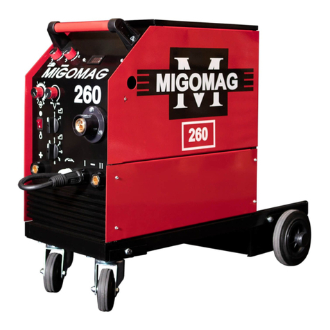
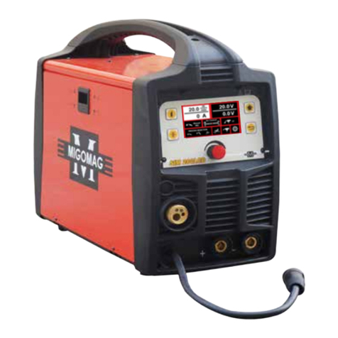
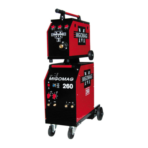
Migomag MOMACDC User manual

Migomag ACDC 200 TIG Inverter
Part Number: MOMACDC
Operators Manual
MIGOMAG
ACDC 200
INVERTER

Migomag Welding Supplies
Your Welding Industrial Specialist
668 Somerville Road, Sunshine VIC 3020
03 9313 3100
www.migomag.com.au
A division of Wesfarmers Industrial & Safety
Record the following informaon for Warranty purposes:
Where Purchased: ______________________________________________________
Purchase Date: _________________________________________________________
Equipment Serial #: _____________________________________________________
THANK YOU FOR YOUR BUSINESS!
Congratulaons on your new MIGOMAG MACHINE. We are proud to have you as our
customer and will strive to provide you with the best service and reliability in the welding
industry. This product is backed by our extensive warranty.
To locate your nearest distributor or Repair agent please call +03 9313 3100, or visit us on
the web at www.migomag.com.au.
This Operang Manual has been designed to instruct you on the correct use and operaon
of your Migomag Welder. Your sasfacon with this product and its safe operaon is our
ulmate concern. Therefore please take the me to read the enre manual, especially
the Safety Precauons. They will help you to avoid potenal hazards that may exist when
working with this product.
Migomag your Welding Industrial Specialist - we are the right choice for all your welding
needs.
Migomag are one of the Market Leaders of Arc Welding Products for your welding needs
from Light industrial to Heavy industrial.

Table of Contents
Secon Page
General Safety Rules 1
Receiving 6
Descripon 6
Unpacking 6
Specicaons 7
Know your Welder 9
Front Control Panel 10
Installaon 11
Operaon 13
Troubleshoong Chart 29
Spare Part Diagram 31
Spare Part List 32
Maintenance, Transportaon and Storage 33
Hazard Warnings 33
Warranty 34
Terms & Condions 35
Migomag TIG Torch 37

Operators Manual
1
General Safety Rules
WARNING: Read and understand all instrucons. Failure to follow all instrucons listed
below may result in serious injury.
CAUTION: Do not allow persons to operate or assemble this MOM ACDC 200 unl they
have read this manual and have developed a thorough understanding of how the MOM
ACDC 200 works.
WARNING: The warnings, cauons, and instrucons discussed in this instrucon manual
cannot cover all possible condions or situaons that could occur. It must be understood
by the operator that common sense and cauon are factors which cannot be built into
this product, but must be supplied by the operator.
1. Your Welding Environment
• The welding machine is not suitable for use in rain
• Keep the environment you will be welding in free from ammable materials
• Always keep a re exnguisher accessible to your welding environment
• Always have a qualied person install and operate this equipment
• Make sure the area is clean, dry and venlated. Do not operate the welder in humid,
wet or poorly venlated areas
• Always have your welder maintained by a qualied technician in accordance with local,
state and naonal codes
• Always be aware of your work environment. Be sure to keep other people, especially
children, away from you while welding
• Keep harmful arc rays shielded from the view of others
• Mount the welder on a secure bench or cart that will keep the welder secure and
prevent it from pping over or falling
2. Your Welder’s Condion
• Check ground cable, power cord and welding cable to be sure the insulaon is not
damaged. Always replace or repair damaged components before using the welder
• Check all components to ensure they are clean and in good operang condion before
use
3. Use of Your Welder
CAUTION! Do not operate the welder if the output cable, electrode, torch, wire or wire
feed system is wet. Do not immerse them in water. These components and the welder
must be completely dry before aempng to use them.
• Follow the instrucons in this manual
• Keep welder in the o posion when not in use
• Connect ground lead as close to the area being welded as possible to ensure a good
ground

Migomag ACDC 200
Model No MOMACDC 2
• Do not allow any body part to come in contact with the welding wire if you are in
contact with the material being welded, ground or electrode from another welder
• Do not weld if you are in an awkward posion. Always have a secure stance while
welding to prevent accidents. Wear a safety harness if working above ground
• Do not drape cables over or around your body
• Wear a full coverage helmet with appropriate shade (see ANSI Z87.1 safety standard)
and safety glasses while welding
• Wear proper gloves and protecve clothing to prevent your skin from being exposed to
hot metals, UV and IR rays
• Do not overuse or overheat your welder. Allow proper cooling me between duty
cycles
• Keep hands and ngers away from moving parts and stay away from the drive rolls
• Do not point torch at any body part of yourself or anyone else
• Always use this welder in the rated duty cycle to prevent excessive heat and failure
4. Specic Areas of Danger, Cauon or Warning
Electrical Shock
WARNING! Electric arc welders can produce a shock that can cause injury or death.
Touching electrically live parts can cause fatal shocks and severe burns. While welding, all
metal components connected to the wire are electrically hot. Poor ground connecons
are a hazard, so secure the ground lead before welding.
• Wear dry protecve apparel: coat, shirt, gloves and insulated footwear
• Insulate yourself from the work piece. Avoid contacng the work piece or ground
• Do not aempt to repair or maintain the welder while the power is on
• Inspect all cables and cords for any exposed wire and replace immediately if found
• Use only recommended replacement cables and cords
• Always aach ground clamp to the work piece or work table as close to the weld area
as possible
• Do not touch the welding wire and the ground or grounded work piece at the same
me
• Do not use a welder to thaw frozen pipes
Fumes and Gases - WARNING!
• Fumes emied from the welding process displace clean air and can result in injury or
death
• Do not breathe in fumes emied by the welding process. Make sure your breathing air
is clean and safe

Operators Manual
3
• Work only in a well-venlated area or use a venlaon device to remove welding
fumes from the environment where you will be working
• Do not weld on coated materials (galvanized, cadmium plated or containing zinc,
mercury or barium). They will emit harmful fumes that are dangerous to breathe. If
necessary use a venlator, respirator with air supply or remove the coang from the
material in the weld area
• The fumes emied from some metals when heated are extremely toxic. Refer to the
material safety data sheet for the manufacturer’s instrucons
• Do not weld near materials that will emit toxic fumes when heated. Vapors from
cleaners, sprays and degreasers can be highly toxic when heated
UV and IR Arc Rays
DANGER! The welding arc produces ultraviolet (UV) and infrared (IR) rays that can cause
injury to your eyes and skin. Do not look at the welding arc without proper eye protecon.
• Always use a helmet that covers your full face from the neck to top of head and to the
back of each ear
• Use a lens that meets ANSI standards and safety glasses. For welders under 160 Amps
output, use a shade 10 lens; for above 160 Amps, use a shade 12. Refer to the ANSI
standard Z87.1 for more informaon
• Cover all bare skin areas exposed to the arc with protecve clothing and shoes. Flame-
retardant cloth or leather shirts, coats, pants or coveralls are available for protecon
• Use screens or other barriers to protect other people from the arc rays emied from
your welding
• Warn people in your welding area when you are going to strike an arc so they can
protect themselves
Fire Hazards
WARNING! Do not weld on containers or pipes that contain or have had ammable,
gaseous or liquid combusbles in them. Welding creates sparks and heat that can ignite
ammable and explosive materials.
• Do not operate any electric arc welder in areas where ammable or explosive
materials are present
• Remove all ammable materials within 35 feet of the welding arc. If removal is not
possible, ghtly cover them with reproof covers
• Take precauons to ensure that ying sparks do not cause res or explosions in hidden
areas, cracks or areas you cannot see
• Keep a re exnguisher close in the case of re

Migomag ACDC 200
Model No MOMACDC 4
• Wear garments that are oil-free with no pockets or cus that will collect sparks
• Do not have on you any items that are combusble, such as lighters or matches
• Keep work lead connected as close to the weld area as possible to prevent any
unknown, unintended paths of electrical current from causing electrical shock and re
hazards
• To prevent any unintended arcs, cut wire back to ¼” sck out aer welding
Hot Materials
CAUTION! Welded materials are hot and can cause severe burns if handled improperly.
• Do not touch welded materials with bare hands
• Do not touch TIG gun nozzle aer welding unl it has had me to cool down
Sparks/Flying Debris
CAUTION! Welding creates hot sparks that can cause injury. Chipping slag o welds
creates ying debris.
• Wear protecve apparel at all mes: ANSI-approved safety glasses or shield, welder’s
hat and ear plugs to keep sparks out of ears and hair
Electromagnec Field - CAUTION!
• Electromagnec elds can interfere with various electrical and electronic devices such
as pacemakers
• Consult your doctor before using any electric arc welder or cung device
• Keep people with pacemakers away from your welding area when welding
• Do not wrap cable around your body while welding
• Wrap TIG gun and ground cable together whenever possible
• Keep TIG gun and ground cables on the same side of your body
Shielding Gas Cylinders can Explode
WARNING! High pressure cylinders can explode if damaged, so treat them carefully.
• Never expose cylinders to high heat, sparks, open ames, mechanical shocks or arcs

Operators Manual
5
• Do not touch cylinder with TIG gun
• Do not weld on the cylinder
• Always secure cylinder upright to a cart or staonary object
• Keep cylinders away from welding or electrical circuits.
• Use the proper regulators, gas hose and ngs for the specic applicaon
• Do not look into the valve when opening it
• Use protecve cylinder cap whenever possible
5. Proper Care, Maintenance and Repair
• Always have power disconnected when working on internal components
• Do not touch or handle PC board without being properly grounded with a wrist strap.
Put PC board in stac proof bag to move or ship
• Do not put hands or ngers near moving parts such as drive rolls of fan
MOM ACDC 200 USE AND CARE
• Do not modify the MOM ACDC 200 in any way. Unauthorized modicaon may
impair the funcon and/or safety and could aect the life of the equipment. There are
specic applicaons for which the MOM ACDC 200 was designed
• Always check of damaged or worn out parts before using the MOM ACDC 200.
Broken parts will aect the MOM ACDC 200 operaon. Replace or repair damaged or
worn parts immediately
• Store idle MOM ACDC 200. When MOM ACDC 200 is not in use, store it in a secure
place out of the reach of children. Inspect it for good working condion prior to
storage and before re-use
Noce:
• If the welder connues to work for to long, the (Protecon Indicator) on the panel
would be on, indicang that the inner temperature rise inside the welder had exceed
the designed permied temperature. At this me, stop the welding work, wait unl
the welder has cooled inside and the (Protecon Indicator) has turned o, then
connue to work again
• Cut o the power switch and Argon valve, before leaving the welding place temporarily
or aer the welding worked nished
• Welders should wear canvas work clothes and welding face shield to prevent arc light
and heat radiaon
• Put light-proof screen around the work area to prevent others inuenced by the arc
lights
• Flammable, explosive items could not be put near the welding area
• Every outlet of the welder should be connected and earthed correctly
Noce: The cover protecon degree of the MOM series Square MOM ACDC pulsed
inverter TIG welder is IP21S.When the welder is operated, do not insert nger or round
sck diameter less than 12.5mm (especially metal sck) into the welder; Do not allow to
press heavily onto the welder.

Migomag ACDC 200
Model No MOMACDC 6
Receiving
Check the equipment received against the shipping invoice to make sure the shipment
is complete and undamaged. If any damage has occurred in transit, please immediately
nofy your supplier.
The Migomag ACDC 200 TIG inverter package contains;
• MIGOMAG ACDC 200 TIG Inverter Power Source
• 4mt TIG torch MMPRO26FX4MT
• Earth cable with earth clamp 4mt
• Welding cable with twist lock electrode holder 4mt
• Gas hose
• (This) Operang Manual MOMACDC
• Regulator
Oponally available:
• Trolley Cart: Part Number - MOMTROLLEY
• Foot Control: Part Number - MOMFOOT
Please read through this owner’s manual carefully before using product. Protect yourself
and others by observing all safety informaon, warnings, and cauons. Failure to comply
with instrucons could result in personal injury and/or damage to product or property.
Please retain these instrucons for future reference.
Descripon
The ACDC 200 series is an inverter welder . This unit uses 1~Phase 240V, 50/60HZ AC
power. The ACDC series is ideal for projects or for light industrial. Sck welding carbon
steel, stainless steel, aluminium.
Unpacking
1. Remove cartons, bags or styrofoam containing the welder machine and accessories.
Check the contents with the packing list below.
ITEM QTY.
ACDC 200 Inverter Welder 1 unit
TIG Torch MMPRO26FX 4mt 1 pc
Welding cable with electrode holder 4mt 1 pc
Earth cable with earth clamp 4mt 1 pc
Gas hose & regulator 1 pc
Operator’s Manual 1 set
2. Aer unpacking unit, inspect carefully for any damage that may have occurred during
transit. Check for loose, missing, or damaged parts. Shipping damage claim must be
led with carrier.

Operators Manual
7
Specicaons
Manufactured to Australian Standard
AS60974-1: 2006
AS610003.3
Primary Voltage
240 Vac, 50/60 Hz
Rated Primary Current (I e)
15 Amps
Maximum Primary Current (I max)
34 Amps
Recommended Generator kVA
10 kVA
Rated Output 15% @ 40 Deg
Duty cycle based on 10 minute cycle me
RATING IP21S
TIG
200 Amp, 18 V, 15% duty
77 Amp, 13.1 V, 100% duty
Welding Current
20-170 Amps on the MMA
10-200 Amps on the ACDC TIG
Open Circuit Voltage
65 V
VRD 12.7 V
Mains Circuit Breaker Rang
29 Amps
Supply plug
15 Amp
Fied Supply Cable
2.5 mm2 Three Core, Heavy Duty PVC
Cooling
Fan cooled, air drawn in through front
grill.
Insulaon
Class H, 150°C Rise
Rods sizes
2.0 to 4.0mm
Tungstan sizes
1.0-3.2mm
If the supply cable is damaged it must
be replaced by the manufacturer, their
service agent or a similarly qualied
person.
Mains Circuit Breaker Rang
29 Amps
Supply plug
15 Amp
Fied Supply Cable
2.5 mm2 Three Core, Heavy Duty PVC
Power Supply Outlet (240 V) & Extension
Lead Rang
15 Amp
Dimension (mm) L X W X H
730 X 320 X 480
Weight
20 kg
Table of contents
Other Migomag Welding System manuals
Popular Welding System manuals by other brands

TAFA
TAFA 30*8B35 owner's manual

Lincoln Electric
Lincoln Electric INVERTEC V350-PRO CE Technical specifications

ESAB
ESAB Buddy Arc 145 instruction manual

CIGWELD
CIGWELD 636804 use instructions

Red-D-Arc
Red-D-Arc DC-400 Operator's manual

Hobart Welding Products
Hobart Welding Products Spool Gun DP 3035-10 owner's manual


