MIKRODEV XIO211-E0N-GD0-B2000 User manual

XIO211 EXPANSION FAMILY
HARDWARE MANUAL
•XIO211-E0N-GD0-B2000 (16 Digital Input)
•XIO211-E0N-GD7-B4000 (8 Digital Output)
•XIO211-E0N-GD1-B4000 (16 Digital Output)
•XIO211-E0N-GD8-B6000 (8 Digital Input, 8 Digital Output)
•XIO211-E0N-GD5-B0000 (8 Relay)
•XIO211-E0N-GD2-B0401 (8 Analog Input, 0-20 mA / 0-10 V)
•XIO211-E0N-GD3-B0000 (8 Analog Output, 0-20 mA)
•XIO211-E0N-GD3-B0800 (8 Analog Output, 0-10 V)
•XIO211-E0N-GD9-B0000 (4 Analog Input, 4 Analog Output, 0-20 mA)
•XIO211-E0N-GD9-B0900 (4 Analog Input, 4 Analog Output, 0-10 V)
•XIO211-E0N-GD4-B0000 (6 RTD Input, PT1000)
•XIO211-E0N-GD4-B0010 (6 RTD Input, PT100)
05 / 2022
MIKRODEV_HM_XIO211_EN
v1.5

1
XIO211 EXTENSIONS FAMILY HARDWARE MANUAL
CONTENT
FIGURES LIST ..................................................................................................................................2
Preface ...........................................................................................................................................3
About Mikrodev .............................................................................................................................4
WARNING!......................................................................................................................................5
Mounting Information....................................................................................................................6
1XIO211 DIGITAL INPUT EXPANSION MODULES ................................................... 7
1.1 GENERAL INFORMATION ............................................................................ 7
1.2 CONNECTION DIAGRAMS ........................................................................... 8
2XIO211 DIGITAL OUTPUT EXPANSION MODULES................................................10
2.1 GENERAL INFORMATION ...........................................................................10
2.2 CONNECTION DIAGRAMS ..........................................................................12
3XIO211 DIGITAL INPUT OUTPUT EXPANSION MODULES ......................................14
3.1 GENERAL INFORMATION ...........................................................................14
3.2 CONNECTION DIAGRAMS ..........................................................................15
4XIO211 RELAY EXPANSION MODULES ...............................................................17
4.1 GENERAL INFORMATION ...........................................................................17
4.2 CONNECTION DIAGRAMS ..........................................................................18
5XIO211 ANALOG INPUT EXPANSION MODULES ..................................................20
5.1 GENERAL INFORMATION ...........................................................................20
5.2 CONNECTION DIAGRAMS ..........................................................................21
6XIO211 ANALOG OUTPUT EXPANSION MODULES................................................23
6.1 GENERAL INFORMATION ...........................................................................23
6.2 CONNECTION DIAGRAMS ..........................................................................24
7XIO211 ANALOG INPUT OUTPUT EXPANSION MODULES ......................................26
7.1 GENERAL INFORMATION ...........................................................................26
7.2 CONNECTION DIAGRAMS ..........................................................................27
8XIO211 RTD INPUT (PT100/PT1000) EXPANSION MODULES ................................29
8.1 GENERAL INFORMATION ...........................................................................29
8.2 CONNECTION DIAGRAMS ..........................................................................30

2
XIO211 EXTENSIONS FAMILY HARDWARE MANUAL
FIGURES LIST
Figure 1 DIN Rail Mounting ..................................................................................... 6
Figure 2 Expansion Module Mounting ....................................................................... 6
Figure 3 GD0 Board Type Connector and Physical Interfaces ....................................... 7
Figure 4 Digital Input Expansion Module Power Connection Diagram ............................ 8
Figure 5 Digital Input Expansion Module Connection Diagram...................................... 9
Figure 6 GD7 Board Type Connector and Physical Interfaces ......................................10
Figure 7 GD1 Board Type Connector and Physical Interfaces ......................................11
Figure 8 Digital Output Expansion Module Power Connection Diagram .........................12
Figure 9 Digital Output Expansion Module Connection Diagram ..................................13
Figure 10 GD8 Board Type Connector and Physical Interfaces ....................................14
Figure 11 Digital Input Output Expansion Module Power Connection Diagram...............15
Figure 12 Digital Input Output Expansion Module Connection Diagram ........................16
Figure 13 GD5 Board Type Connector and Physical Interfaces ....................................17
Figure 14 Relay Expansion Module Power Connection Diagram ...................................18
Figure 15 Relay Output Expansion Module Connection Diagram ..................................19
Figure 16 GD2 Board Type Connector and Physical Interfaces ....................................20
Figure 17 Analog Input Expansion Module Power Connection Diagram.........................21
Figure 18 Analog Input Expansion Module Connection Diagram ..................................22
Figure 19 GD3 Board Type Connector and Physical Interfaces ....................................23
Figure 20 Analog Output Expansion Module Power Connection Diagram.......................24
Figure 21 Analog Output Expansion Module Connection Diagram ................................25
Figure 22 GD9 Board Type Connector and Physical Interfaces ....................................26
Figure 23 Analog Input Output Expansion Module Power Connection Diagram ..............27
Figure 24 Analog Input Output Expansion Module Connection Diagram........................28
Figure 25 GD4 Board Type Connector and Physical Interfaces ....................................29
Figure 26 RTD Input Expansion Module Power Connection Diagram.............................30
Figure 27 RTD Input Expansion Module Connection Diagram ......................................31

3
XIO211 EXTENSIONS FAMILY HARDWARE MANUAL
Preface
Mikrodev XIO211 series expansion modules are used together with MP211 series
PLC and RTU300 series RTU(Remote Teminal Unit) products. There are 12
different types of XIO211 expansion modules:
-XIO211-E0N-GD0-B2000 (16 Digital Input)
-XIO211-E0N-GD7-B4000 (8 Digital Output)
-XIO211-E0N-GD1-B4000 (16 Digital Output)
-XIO211-E0N-GD8-B6000 (8 Digital Input, 8 Digital Output)
-XIO211-E0N-GD5-B0000 (8 Relay)
-XIO211-E0N-GD2-B0401 (8 Analog Input, 0-20 mA / 0-10 V)
-XIO211-E0N-GD3-B0000 (8 Analog Output, 0-20 mA)
-XIO211-E0N-GD3-B0800 (8 Analog Output, 0-10 V)
-XIO211-E0N-GD9-B0000 (4 Analog Input, 4 Analog Output, 0-20 mA)
-XIO211-E0N-GD9-B0900 (4 Analog Input, 4 Analog Output, 0-10 V)
-XIO211-E0N-GD4-B0000 (6 RTD Input, PT1000)
-XIO211-E0N-GD4-B0010 (6 RTD Input, PT100)
This document describes the hardware features of XIO211 series devices.
Please follow our website www.mikrodev.com for the up to date version of the document.

4
XIO211 EXTENSIONS FAMILY HARDWARE MANUAL
About Mikrodev
Since 2006, MIKRODEV has been developing and manufacturing industrial control and
communication products. MIKRODEV serves the system integrators in the public and
private sector, OEM and end users.
Our products are manufactured complying with the quality standards required by the
industrial automation industry and the quality of our products are proved on the field for
many years
MIKRODEV is one of the few companies in the world that has its own designed IEC 61131-
3 compliant library for its programmable logic control devices. In addition, the open,
flexible, programmable SCADA solution developed by MIKRODEV is also available to
customers.
MIKRODEV products' performance and wide range of applications make them possible for
customers to achieve faster, simplified and cost-effective results.

5
XIO211 EXTENSIONS FAMILY HARDWARE MANUAL
WARNING!
✓Please take care of the following issues when using Mikrodev devices.
✓Since the unit operates with 24 VDC (12-36 VDC) voltage, you should take care of
the voltage level that the unit is connected to. If a voltage above this voltage level
is applied, the device may be damaged and may be out of warranty.
✓Make sure that the energy connection of your device is connected to the ground or
to a properly grounded terminal.
✓Make sure that the environment in which your device is being used is free of
moisture, electric shock, vibration and dust.
✓Pay attention to the supply voltage and the connections of the product. Mikrodev is
not responsible for any issues due to power failure since there is no auxiliary supply
(UPS) on the device.
✓The fuse to be used must be a FF super fast type and current limit value 1A.
✓Do not use the device under conditions other than the environmental conditions
specified in the "Electrical Specifications" section (humidity, dust, liquid and
temperature, etc.)
✓Removing the warranty label on the product or removing the protective case will void
the warranty.
✓Products that are damaged, boxes have been changed and other brand labels are
affixed are not covered by the warranty.
✓The appliance must not be cleaned with solvents (thinner, benzine, acid etc.) or with
abrasive cleaning agents.
✓Only dry cloth should be used when cleaning the appliance.
✓Do not open the device by removing the case of the appliance, do not interfere with
the electronic components and circuits. There is no user-replaceable part inside the
device.
✓If there is a problem or malfunction on your device, it should only be repaired by
an authorized service. Installation and electrical connections must be made by
technical personnel in accordance with the instructions in the operating manual.
Failure to comply with these rules may result in death, serious injury or property
damage
6
XIO211 EXTENSIONS FAMILY HARDWARE MANUAL
Mounting Information
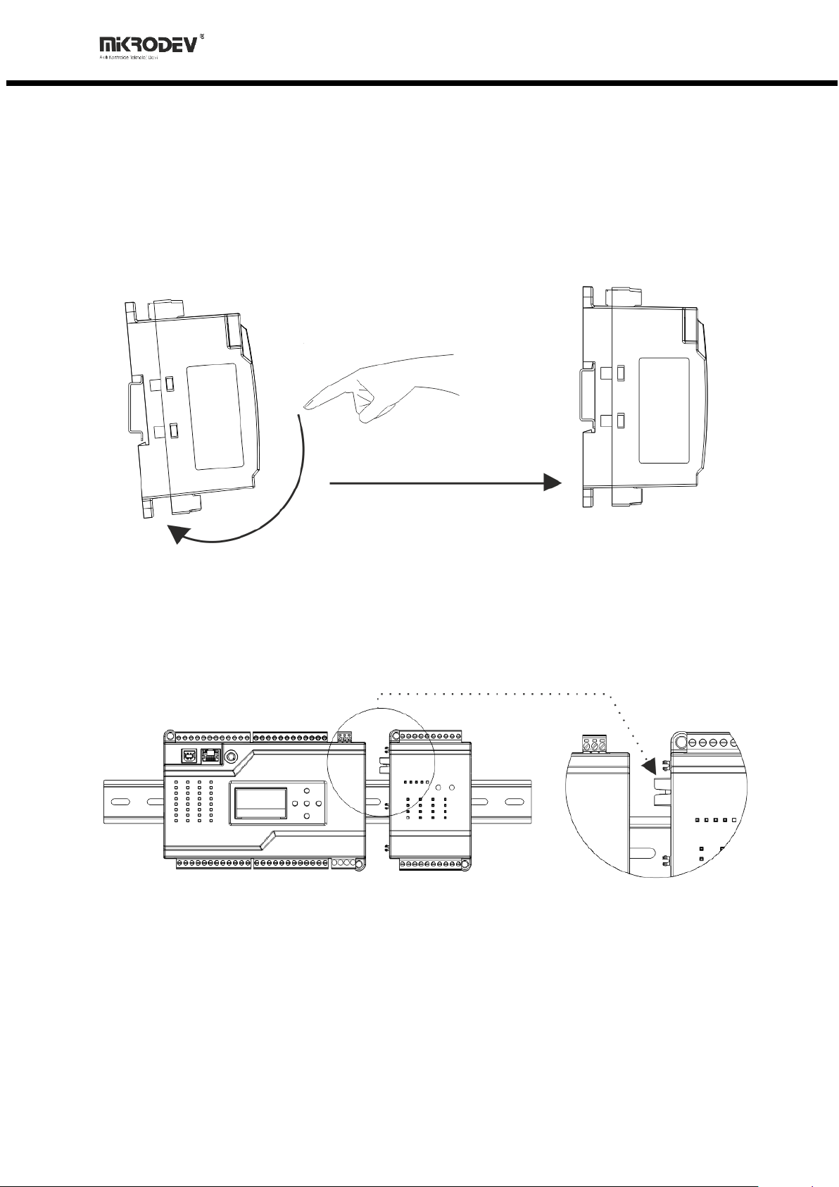
DIN Rail Installation
First, the upper part of the device is mounted on the DIN rail. Then, with the help of the
springs behind the device, when a lightly force is applied to the lower part, the device
locates into the DIN rail easily and the montage is completed (See Figure 1).
Figure 1 DIN Rail Mounting
Expansion Installation
Assembly between MP211 series PLC or RTU300 series RTU products and XIO211 series
expansion modules is carried out by sliding the tabs over the rail so that the tabs overlap
each other.
Figure 2 Expansion Module Mounting

7
XIO211 EXTENSIONS FAMILY HARDWARE MANUAL
1XIO211 DIGITAL INPUT EXPANSION MODULES
1.1 GENERAL INFORMATION
1.1.1 GD0 Board Type(16 Digital Input) Physical Interfaces
Figure 3 GD0 Board Type Connector and Physical Interfaces
1
Device Power (V+) Connection
2
Device Power (V-) Connection
3
N/A
4
Digital Input Ground Connection
5
Digital Input Connections
6
System Power LED
7
System Running LED
8
System Error LED
9
CANBUS Data Receiving LED
10
CANBUS Data Sending LED
11
Expansion ID Assignment, Second Digit
12
Expansion ID Assignment, First Digit
13
Digital Input Status LEDs
14
Expansion Connector

8
XIO211 EXTENSIONS FAMILY HARDWARE MANUAL
1.1.2 General Device Specifications
SPECIFICATION
ITEM
DESCRIPTION
Electrical
Supply (Standard)
24 VDC (12-36VDC)
Supply (Optional)
Over Expansion Bus
Power
<13W
Power Protection
Yes
Enviromental
Conditions
Operating Temperature
-20…+60 C
Storage Temperature
-40…+85 C
Humidity
5…95 RH
Operating Altitude
0…2000 m
ID Assign
Rotary Switch
Between 0-99
1.2 CONNECTION DIAGRAMS
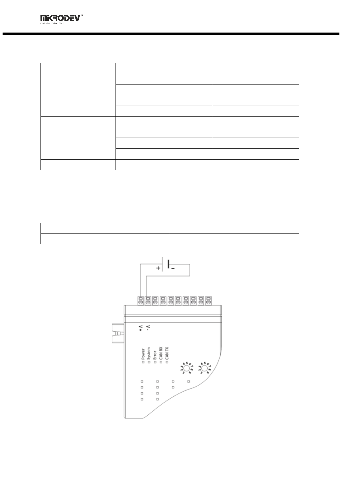
1.2.1 Supply Connection
Supply:
12-36 VDC, Protected
Power:
<13 W
Figure 4 Digital Input Expansion Module Power Connection Diagram
9
XIO211 EXTENSIONS FAMILY HARDWARE MANUAL
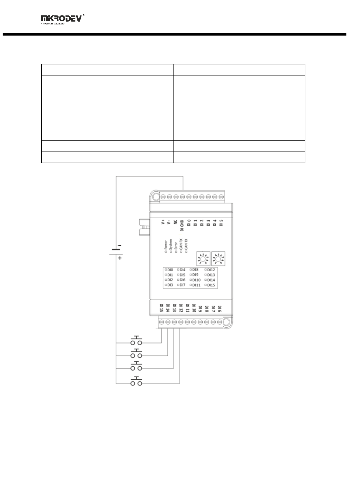
1.2.2 Digital Inputs
Order Code:
XIO211-E0N-GD0-B2000
Module Input:
16 Channel, PNP
Module Input Range:
0-50 VDC
ON Voltage Range:
9-50 VDC
OFF Voltage Level:
0-5 VDC
Input Impedance:
> 2M
Isolation:
Optical
OFF to ON Response:
20 us
ON to OFF Response:
90 us
Figure 5 Digital Input Expansion Module Connection Diagram

10
XIO211 EXTENSIONS FAMILY HARDWARE MANUAL
2XIO211 DIGITAL OUTPUT EXPANSION MODULES
2.1 GENERAL INFORMATION
2.1.1 GD7 Board Type(8 Digital Output) Physical Interfaces
Figure 6 GD7 Board Type Connector and Physical Interfaces
1
Device Power (V+) Connection
2
Device Power (V-) Connection
3
Digital Output Ground Connection
4
Digital Output Supply Connection
5
Digital Output Connections
6
N/A
7
System Power LED
8
System Running LED
9
System Error LED
10
CANBUS Data Receiving LED
11
CANBUS Data Sending LED
12
Expansion ID Assignment, Second Digit
13
Expansion ID Assignment, First Digit
14
Digital Output Status LEDs
15
Expansion Connector

11
XIO211 EXTENSIONS FAMILY HARDWARE MANUAL
2.1.2 GD1 Board Type(16 Digital Output) Physical Interfaces
Figure 7 GD1 Board Type Connector and Physical Interfaces
1
Device Power (V+) Connection
2
Device Power (V-) Connection
3
Digital Output Ground Connection
4
Digital Output Supply Connection
5
Digital Output Connections
6
System Power LED
7
System Running LED
8
System Error LED
9
CANBUS Data Receiving LED
10
CANBUS Data Sending LED
11
Expansion ID Assignment, Second Digit
12
Expansion ID Assignment, First Digit
13
Digital Output Status LEDs
14
Expansion Connector
12
XIO211 EXTENSIONS FAMILY HARDWARE MANUAL
2.1.3 General Device Specifications
SPECIFICATION
ITEM
DESCRIPTION
Electrical
Supply (Standard)
24 VDC (12-36VDC)
Supply (Optional)
Over Expansion Bus
Power
<13W
Power Protection
Yes
Enviromental
Conditions
Operating Temperature
-20…+60 C
Storage Temperature
-40…+85 C
Humidity
5…95 RH
Operating Altitude
0…2000 m
ID Assign
Rotary Switch
Between 0-99
2.2 CONNECTION DIAGRAMS
2.2.1 Supply Connection
Supply:
12-36 VDC, Protected
Power:
<13 W
Figure 8 Digital Output Expansion Module Power Connection Diagram
13
XIO211 EXTENSIONS FAMILY HARDWARE MANUAL
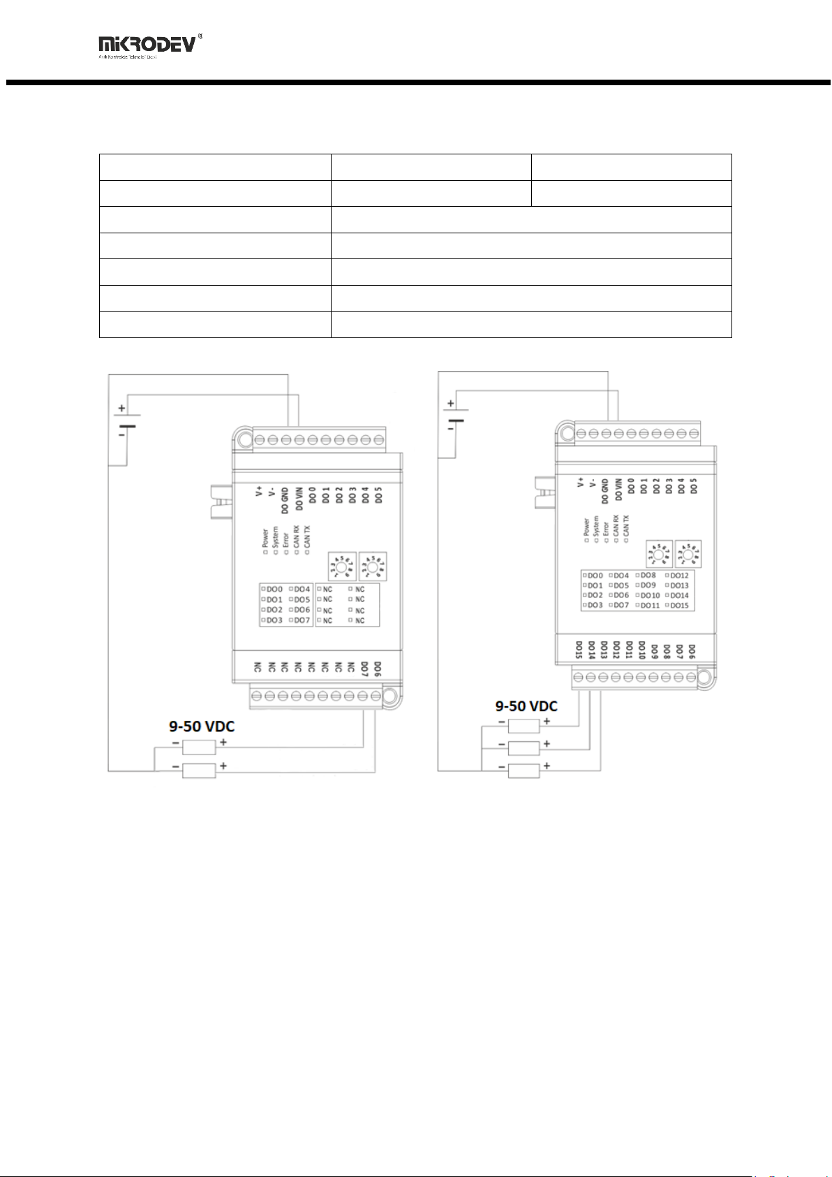
2.2.2 Dijital Outputs
Order Code:
XIO211-E0N-GD7-B4000
XIO211-E0N-GD1-B4000
Module Output:
8 Channel, Mosfet Output
16 Channel, Mosfet Output
Module Output Type:
PNP Transistor
Module Output Range:
12-36 VDC
Module Output Current:
2 A @ 30 VDC
Module Output GND Common:
1 GND (16 Point/ Common)
Isolation:
Optical
Figure 9 Digital Output Expansion Module Connection Diagram

14
XIO211 EXTENSIONS FAMILY HARDWARE MANUAL
3XIO211 DIGITAL INPUT OUTPUT EXPANSION MODULES
3.1 GENERAL INFORMATION
3.1.1 GD8 Board Type(8 Digital Input, 8 Digital Output) Physical
Interfaces
Figure 10 GD8 Board Type Connector and Physical Interfaces
1
Device Power (V+) Connection
2
Device Power (V-) Connection
3
Digital Output Supply Connection
4
Digital Input/Output Ground Connection
5
Digital Input Connections
6
Digital Output Connections
7
System Power LED
8
System Running LED
9
System Error LED
10
CANBUS Data Receiving Led
11
CANBUS Data Sending Led
12
Expansion ID Assignment, Second Digit
13
Expansion ID Assignment, First Digit
14
Digital Input Status Leds
15
Digital Output Status Leds
16
Expansion Connector

15
XIO211 EXTENSIONS FAMILY HARDWARE MANUAL
3.1.2 General Device Specifications
SPECIFICATION
ITEM
DESCRIPTION
Electrical
Supply (Standard)
24 VDC (12-36VDC)
Supply (Optional)
Over Expansion Bus
Power
<13W
Power Protection
Yes
Enviromental
Conditions
Operating Temperature
-20…+60 C
Storage Temperature
-40…+85 C
Humidity
5…95 RH
Operating Altitude
0…2000 m
ID Assign
Rotary Switch
Between 0-99
3.2 CONNECTION DIAGRAMS
3.2.1 Supply Connection
Supply:
12-36 VDC, Protected
Power:
<13 W
Figure 11 Digital Input Output Expansion Module Power Connection Diagram

16
XIO211 EXTENSIONS FAMILY HARDWARE MANUAL
3.2.2 Digital Input ve Outputs
Order Code:
XIO211-E0N-GD8-B6000
Module Input:
8 Channel, PNP
Module Input Range:
0-50 VDC
ON Voltage Range:
9-50 VDC
OFF Voltage Level:
0-5 VDC
Input Impedance:
> 2M
Isolation:
Optical
OFF to ON Response:
20 us
ON to OFF Response:
90 us
Module Output
8 Channel, Mosfet Output
Module Output Type
PNP Transistor
Module Output Range
12-36 VDC
Module Output Current
2 A @ 30 VDC
Module Output GND Common
1 GND (16 Point/ Common)
Isolation
Optical
Figure 12 Digital Input Output Expansion Module Connection Diagram

17
XIO211 EXTENSIONS FAMILY HARDWARE MANUAL
4XIO211 RELAY EXPANSION MODULES
4.1 GENERAL INFORMATION
4.1.1 GD5 Board Type(8 Relay) Physical Interfaces
Figure 13 GD5 Board Type Connector and Physical Interfaces
1
Device Power (V+) Connection
2
Device Power (V-) Connection
3
N/A
4
Relay NO(Normally Open) Contact
5
Relay COM(Common) Contact
6
System Power LED
7
System Running LED
8
System Error LED
9
CANBUS Data Receiving Led
10
CANBUS Data Sending Led
11
Expansion ID Assignment, Second Digit
12
Expansion ID Assignment, First Digit
13
Relay Status Information LED
14
Expansion Connector

18
XIO211 EXTENSIONS FAMILY HARDWARE MANUAL
4.1.2 General Device Specifications
SPECIFICATION
ITEM
DESCRIPTION
Electrical
Supply (Standard)
24 VDC (12-36VDC)
Supply (Optional)
Over Expansion Bus
Power
<13W
Power Protection
Yes
Enviromental
Conditions
Operating Temperature
-20…+60 C
Storage Temperature
-40…+85 C
Humidity
5…95 RH
Operating Altitude
0…2000 m
ID Assign
Rotary Switch
Between 0-99
4.2 CONNECTION DIAGRAMS
4.2.1 Supply Connection
Supply:
12-36 VDC, Protected
Power:
<13 W
Figure 14 Relay Expansion Module Power Connection Diagram

19
XIO211 EXTENSIONS FAMILY HARDWARE MANUAL
4.2.2 Relay Outputs
Order Code:
XIO211-E0N-GD5-B0000
Relay Output:
8 Channel
Relay Contact Output:
COM-NO (Normally Open)
Relay Contact Max. Current Value:
5A@250V AC –3A@30V DC
Isolation:
Dry Contact
Figure 15 Relay Expansion Module Connection Diagram
This manual suits for next models
11
Table of contents


