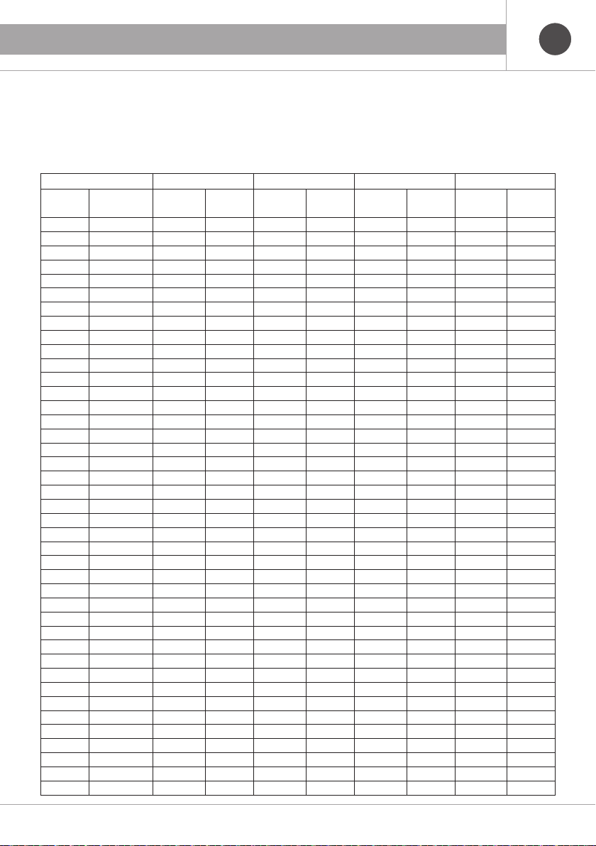
– Temperature: 15 °C
– Pressure: 1013.25 mbar – LPG density: 1.864 kg/m³
– Lower calorific LPG value: 27000 kcal/m³
LPG 16 20 26 32
Power
(kW)
Flow Rate
(m³/h)
Δp
(mbar/m)
Speed
(m/s)
Δp
(mbar/m)
Speed
(m/s)
Δp
(mbar/m)
Speed
(m/s)
Δp
(mbar/m)
Speed
(m/s)
5 0,154 0,010 0,379 0,021 0,213 0,002 0,137 0,0002 0,081
6 0,185 0,013 0,455 0,029 0,256 0,003 0,164 0,0003 0,097
7 0,216 0,018 0,531 0,000 0,299 0,000 0,191 0,0004 0,113
8 0,247 0,023 0,607 0,048 0,341 0,005 0,218 0,0006 0,129
9 0,278 0,028 0,683 0,059 0,384 0,007 0,246 0,0007 0,145
10 0,309 0,034 0,758 0,072 0,427 0,008 0,273 0,0008 0,162
11 0,340 0,040 0,834 0,085 0,469 0,009 0,300 0,0010 0,178
12 0,370 0,047 0,910 0,100 0,512 0,011 0,328 0,0011 0,194
13 0,401 0,054 0,986 0,115 0,555 0,013 0,355 0,0013 0,210
14 0,432 0,062 1,062 0,132 0,597 0,015 0,382 0,0015 0,226
15 0,463 0,070 1,138 0,149 0,640 0,016 0,410 0,0017 0,242
16 0,494 0,079 1,214 0,167 0,683 0,018 0,437 0,0019 0,258
17 0,525 0,088 1,289 0,187 0,725 0,021 0,464 0,0021 0,275
18 0,556 0,097 1,365 0,207 0,768 0,023 0,491 0,0024 0,291
19 0,586 0,107 1,441 0,228 0,811 0,025 0,519 0,0026 0,307
20 0,617 0,118 1,517 0,250 0,853 0,028 0,546 0,0029 0,323
21 0,648 0,129 1,593 0,273 0,896 0,030 0,573 0,0031 0,339
22 0,679 0,140 1,669 0,297 0,939 0,033 0,601 0,0034 0,355
23 0,710 0,152 1,744 0,322 0,981 0,035 0,628 0,0037 0,372
24 0,741 0,164 1,820 0,347 1,024 0,038 0,655 0,0040 0,388
25 0,772 0,176 1,896 0,374 1,067 0,041 0,683 0,0043 0,404
26 0,802 0,189 1,972 0,401 1,109 0,044 0,710 0,0046 0,420
27 0,833 0,202 2,048 0,429 1,152 0,047 0,737 0,0049 0,436
28 0,864 0,216 2,124 0,459 1,195 0,051 0,765 0,0053 0,452
29 0,895 0,230 2,199 0,488 1,237 0,054 0,792 0,0056 0,469
30 0,926 0,244 2,275 0,519 1,280 0,057 0,819 0,0060 0,485
31 0,957 0,259 2,351 0,551 1,323 0,061 0,846 0,0063 0,501
32 0,988 0,275 2,427 0,583 1,365 0,064 0,874 0,0067 0,517
33 1,019 0,290 2,503 0,616 1,408 0,068 0,901 0,0071 0,533
34 1,049 0,306 2,579 0,650 1,451 0,072 0,928 0,0075 0,549
35 1,080 0,323 2,655 0,685 1,493 0,076 0,956 0,0079 0,565
40 1,235 0,410 3,034 0,871 1,706 0,096 1,092 0,0100 0,646
45 1,389 0,507 3,413 1,077 1,920 0,119 1,229 0,0124 0,727
50 1,543 0,613 3,792 1,302 2,133 0,144 1,365 0,0150 0,808
60 1,852 0,851 4,551 1,808 2,560 0,199 1,638 0,0208 0,969
70 2,160 1,123 5,309 2,386 2,986 0,263 1,911 0,0275 1,131
80 2,469 1,429 6,068 3,034 3,413 0,335 2,184 0,0349 1,292
90 2,778 1,766 6,826 3,751 3,840 0,414 2,457 0,0432 1,454
100 3,086 2,135 7,584 4,534 4,266 0,500 2,730 0,0522 1,616
110 3,395 2,534 8,343 5,382 4,693 0,594 3,003 0,0619 1,777
120 3,704 2,964 9,101 6,295 5,119 0,694 3,276 0,0725 1,939
Reference values for LPG gas:
7
GB
3. INSTALLATION