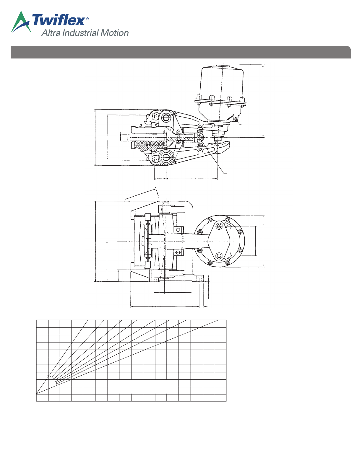
GMR-SH & GMR40-SH Disc Brake Caliper - Spring Applied, Hydraulically Released
the pushrod are engaged in the slot in the caliper arm. (A 17mm A/F spanner will fit the flats on the
push rod).
N.B. Keep fingers clear of the space between push rod and caliper arm at all times.
If an inclined mounting kit is fitted, the stop screw should be re-adjusted to maintain equal pad clearance
on either side of the disc.
2.5 Pad wear can be monitored by observing the gap between the lugs on the pads pressure plates and the
machined surfaces on the caliper frame, when the brake is applied. Pads must be replaced (see 3.2)
before the gap is reduced to zero. (The maximum allowable wear on a pad is 10mm).
3. Maintenance
CALIPER
3.1 Ensure that the brake pad and disc remain free from oil and grease. Clean the disc as required. If the
pads become contaminated they should be replaced. Carry out any periodic statutory testing that is
required, or otherwise check for satisfactory performance.
3.2 Pad replacement is carried out from the rear of the caliper; DO NOT release the spring clips which attach
the pressure plates to the caliper arms. With the brake off (retraction screw may be fitted as a safety
screw) remove the caliper return springs and the keep plates. If an inclined mounting kit is fitted, remove
this also. Withdraw the pads to the rear and lift out. (The hole in the end of the pad retaining plates is
provided to assist in withdrawing the pad). Fit the new pads, ensuring that the slotted retaining plate is
located around the keep disc on the pressure plate; the pads should slide freely into position. Replace
remaining parts. Re-adjust the pushrod, as in (2.4), and the stop screw if fitted.
3.3 The surface of the caliper arm on which the thruster pushrod bears should be kept well greased. The
knuckle joints between the caliper arms and the pressure plates should be cleaned occasionally, and a
small amount of grease applied; the joints may be levered apart slightly against the pressure of the spring clip.
Occasionally, or if caliper is not operating freely, inject a small amount of grease via grease nipples to
lubricate the pivot pins, then rotate pins to distribute the grease. Any grease exuding past the ‘0’-rings
should be wiped off. The pins may be turned by gripping the knurled end at the top of the caliper.
After extended (one million operations or three years) use, the pivot pins should be withdrawn, cleaned,
replaced and regreased, or replaced if badly worn.
In order not to damage the 0-ring seals on the pins, use the following procedure. Remove the top circlip,
push pin down until the lower circlip and ‘0’-ring can be removed, then withdraw the pin upwards. To
refit, reverse this procedure.
THRUSTER
3.4 Clean the pushrod as required, and inspect hydraulic connections and hoses.
3.5 In the event of leakage or malfunction of the thruster, the following parts can be inspected and replaced if
necessary, using the procedures described below, without decompressing the spring pack:-
Piston Seal (19)
Rod Seal (18)
Bush (17)
Wiper Seal (16)
Pushrod (3)
Replacement of any other components, such as rear bush (20) and springs, requires the spring pack to
be decompressed. This is not covered in these instructions, and should only be carried out by Twiflex or
their Agents. If the push rod is damaged, replace it first, as in 3.11. Otherwise proceed as below.
WARNING:- DO NOT ATTEMPT TO DECOMPRESS THE SPRINGS BY UNSCREWING THE RETRACTION SCREW.
Thruster Servicing
3.6 With the brake off, remove red cap (22), insert retraction screw and screw it fully in; finger tight is
sufficient. (If the thruster will not retract, the brake should be released using the retraction screw, which
should be well lubricated). Disconnect the hydraulic supply and remove thruster from caliper.
The surface of the pushrod should be smooth and free from serious scoring or bruising which could
damage the bush. Note that the pushrod cannot be removed while the thruster is dismantled.
For removal and replacement of the push rod see 3.11.
Withdraw the screws (28), and remove the front cap (1), and piston (5).
3.7 Leakage of hyraulic fluid may be caused by damage to the piston seals or to the housing. The piston may