Reg Office: Pointer Farm, Great North Rd, Peckfie d, South Mi ford, LEEDS LS25 5LH United
Kingdom
Reg Number: 4222329 Te 01977 683665 Fax 01977 681465 www.mi inst.com
Page 2
PWM Outputs:
4 +/- L D PWM output connections via screw terminals at up to 3 amps per channel @ 12
Vdc.
The DMX value for the base address controls the PWM on channel 1. A value of 0 will
switch the load completely OFF and a value of 255 will switch the load completely ON, a
value of 128 will generate a 50% duty PWM signal running at 667Hz. The resolution of the
PWM stream is 8-bit.
The DMX value on the base address +1 controls channel 2, etc.
The PWM signal operates at default value (on channel 1 only) if a valid DMX signal is not
being received: See LED Display panel.
Outputs:
The 4 output channels are rated at 3 Amps each @ 12VDC and are arranged as open
collector devices.
Base Address Selection:
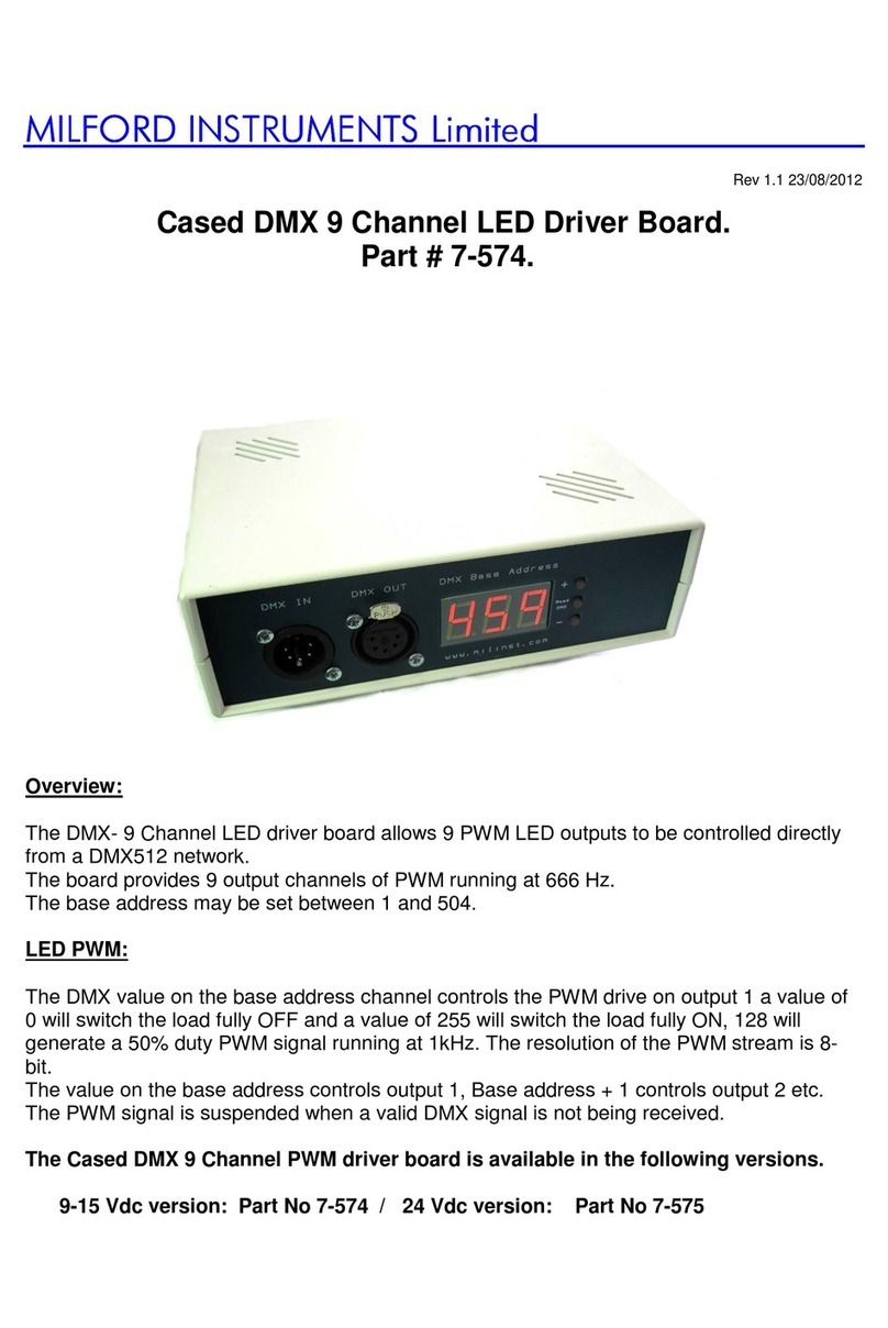
The base address may be set between 1 and 509 using the up / down L D display panel
buttons and is retained at power down.
Connections:
If driving L Ds, the L Ds should have their anodes connected to the “+” terminal and their
cathodes connected via a suitable current limiting resistor to the relevant “
-
“ terminal on the
board see connection diagram.
Reset Button: Auxiliary connection point available.
LED Display panel.
The L D display panel shows the current DMX base address. In normal running, pressing
the ‘Read DMX’ button will display the received DMX value on Channel 1.
Default DMX setting:
To set the default DMX value for channel 1 in fault condition, press and hold down the reset
button on the main PCB and press and hold the ‘Read DMX’ button on the display then
release the reset button and then the read DMX button. The display will now show the default
output value on channel1 if the DMX signal fails. This value may be set between 0-255 with
the Up/Down buttons. When the correct level has been selected press the read DMX button
once more and the board will return to normal operation.
When adjusting the default DMX setting the display will alternate between the output value
and - - -
N.B. changes to the DMX default value are not saved until the read DMX button is
pressed for the second time.
Indicators:
Power applied L D display is active
DMX Fault:
The display will alternately flash - - - / Err
when a suitable DMX input is not being received.
Mechanical:
PCB size: 112mm x 72mm. 4mm mounting holes at 104mm x 64mm
