Millar MPVS Ultra User manual

1
MPVS Ultra
Signal Conditioning
Hardware
User Guide

2
Table of Contents
I. Introduction.................................................................................................2
II. Getting Started............................................................................................4
Components and Contents .................................................................................................4
Initial Setup ........................................................................................................................4
Normal Operation...............................................................................................................8
III. Detailed Operation....................................................................................11
Hardware Connections.....................................................................................................11
Catheter Configuration tab...............................................................................................13
Catheter Calibration Tab..................................................................................................18
Rho Cuvette Tab ..............................................................................................................21
IV. Theory of Operation..................................................................................25
The Conductance Method ................................................................................................25
Dual Field Excitation .......................................................................................................26
Resistivity – Rho Cuvette ................................................................................................27
Resistivity – Dip Cuvette .................................................................................................28
IECG vs. ECG..................................................................................................................28
Strain Gauge Pressure Sensors and Catheter Tip Transducers ........................................28
Additional guidelines .......................................................................................................29
V. Troubleshooting, System Maintenance and Specifications..................31
Hardware..........................................................................................................................33
Cables...............................................................................................................................34
Technical Specifications ..................................................................................................35
Technical Support ............................................................................................................38
Recommended accessories...............................................................................................39
Warranty...........................................................................................................................42
I. Introduction
The MPVS Ultra simultaneously and continuously measures high-fidelity left ventricular
pressure and volume from the intact beating hearts of large and small laboratory animals.
The MPVS Ultra can be used on animals as small as transgenic mice and as large as full
grown horses. Using the MPVS Ultra, cardiovascular pressure and volume signals can be
plotted against each other in real time, generating the characteristic pressure-volume (P-V)
User Guide

M.I. P/N 004-2163 Rev. C 3
loops that are an excellent illustration of the cardiac cycle in normal or diseased conditions
of the living heart.
With the MPVS Ultra, P-V loops may be captured during pharmacological, therapeutic
and hemodynamic interventions, allowing comprehensive, beat-by-beat evaluation of the
fundamental mechanical properties of the heart.
The MPVS Ultra supports the use of Millar’s ultra-miniature P-V catheters for small
animal studies and multi-segment P-V catheters for large animal studies. Both the small
and large animal catheters couple a high-fidelity pressure sensor with volume electrodes
spaced to match the longitudinal diameter of the left ventricle. The electrodes allow
volume data to be acquired across a single segment of the left ventricle.
The MPVS Ultra has an internal 20 kHz fixed-frequency oscillator, which generates either
a 20µA or 100µA RMS sine-wave current that creates an electric field within the left
ventricle of the heart. The system measures a corresponding voltage that is proportional to
the electric field. The system continuously measures this voltage across the receiving
electrodes. The measured voltage changes during the cardiac cycle as the left ventricular
blood volume rises (diastolic filling phase) and falls (systolic ejection phase).
The measured voltage decreases as volume increases (resistance of blood pool decreases,
conductance of blood pool increases) and the measured voltage increases as volume
decreases (resistance of blood increases, conductance of blood pool decreases). The system
then converts measured voltages into ventricular conductance, which is proportional to the
changes in ventricular volume as stated above.
The MPVS Ultra also measures high fidelity pressure signals using a Millar catheter. The
solid-state pressure sensor uses the same technology found in Millar’s extensive line of
Mikro-Tip®catheter pressure transducers. The use of the pressure sensor located between
the conductance/volume electrodes allows the simultaneous measurement of pressure and
conductance/volume, enabling a researcher to obtain high quality P-V loops from the
rapidly beating hearts of small animals. The MPVS Ultra system should ONLY be used
with a Millar catheter.

M.I. P/N 004-2163 Rev. C 4
II. Getting Started
Components and Contents
MPVS Ultra Control Interface software
PVAN Ultra analysis software
MPVS Ultra unit
MPVS Ultra P-V cable (CEC-10E or CEC-4E)
Mikro-Tip®P-V Catheter
Rho calibration cuvette (for measuring resistivity)
BNC cables
USB cable
Optional: ECG cable (EPC-10UT, EPC-10A, EPC-4UT, EPC-4A)
Optional: Thermodilution cable (SGC-10A, SGC-4A)
Not included: Data acquisition system such as ADInstruments PowerLab 16/3
Data Acquisition Hardware with Chart DAQ software (v. 5.2 or higher)
Not included: Computer with MS Windows operating system (XP or later) and
MS Excel
Initial Setup
Typical Setup
Place the MPVS Ultra (and any related equipment) on a solid surface where the
enclosure(s) will be protected from exposure to liquids and heat sources. Be sure that
when the cables are connected they are not tight or sharply bent as this may damage the
internal wires. The MPVS Ultra does not require ventilation, but most computers and data
acquisition systems will. Position the equipment so that cables can easily be disconnected,
especially the power cord, in case of an emergency. This system must be connected to an
easily accessible wall outlet that remains accessible after installation so that the power cord
can be disconnected in case of an emergency. Failure to operate the system according to
the instructions provided in this manual may cause a hazardous condition that may lead to
damage or personal injury.
Control Interface Installation
Install the MPVS Control Interface before connecting the system to your computer. Insert
the disk into your computer. If the installation dialog does not automatically launch, run
setup.exe from the CD or the software downloaded from the Millar web site. After
installation is complete, store the disk and the serial number in a secure location for future
use.
USB Control
The system is controlled by the MPVS Ultra Control Interface. A USB cable is included
with the system. Connect the MPVS Ultra hardware to your computer before turning it on.
The first time that a computer is connected to an MPVS Ultra system, software drivers will
be installed; this installation will not be necessary after the first installation.
Gettin
g
Started

M.I. P/N 004-2163 Rev. C 5
Power Input
The system has a universal power input, so it can accept 110V or 220V at 60Hz or 50Hz
(47Hz minimum, 63Hz maximum). The system includes two power cords: one with a
North American (NEMA) 5-15 plug and one with a European CEE (7)VII plug. If your
region requires a different plug type, contact your distributor or see the Technical Support
section for a source of power cords. See the Technical Specifications section for more
specific information about the power requirements.
CAUTION – Reliable earth connection is required. This device is designed to be
connected to protective earth through the power cord and the wall outlet. If your wall
outlets do not have a grounding conductor, please contact an electrician for installation. Do
not use groundless adapters.
The power switch is located on the back panel of the MPVS Ultra.
The green LED on the front panel will indicate whether the MPVS Ultra is turned on.
System Ground
For operator safety and signal noise reduction, an equipotential (earth ground) post is
located on the rear panel. This terminal can be used to ground the subject and any sensitive
equipment. Keep electrically noisy equipment such as lamps, heaters, and electrocautery
generators as far from the system as possible. See the Recommended Accessories section
for ordering information for equipotential cables specifically made for this type of terminal.
Data Acquisition
The system can be connected to any data acquisition system with sufficient voltage input
channels to accept the desired number of signals. Users with an ADInstruments PowerLab
system should refer to the ADInstruments PowerLab setup section for specific instructions.
For users with other data acquisition systems, packages of BNC-to-BNC cables are
available. See the Recommended Accessories section for ordering information.
Connect each channel of the MPVS Ultra to the data acquisition system. Millar
recommends that the order of the channels be consistent with the order in which they are
arranged on the front panel of the MPVS Ultra. (Channels on the front panel are numbered
1 through 11.) A user may choose not to connect certain outputs, but consistency from one
study to the next is important to prevent problems in analyzing the data. Most users will
not use the Cuvette Output and Cuvette Temperature signals available on the rear panel.
(The Cuvette Temperature output can be used for a thermodilution measurement. See the
“Theory of Operation –Temperature Measurement” section for details.)
Pressure-Volume Cable
The P-V cable connects the catheter to the system. The cable is available in two different
lengths according to the users’ needs.
One end connects directly to the white low profile and gray circular connectors on the
catheter and the other end plugs into the color-coded (black) pressure-volume channel
receptacle on the front of the MPVS Ultra.
This cable carries the excitation signal from the MPVS Ultra to the catheter electrodes and
returns the pick-up signal from the sensing electrodes. This cable also carries the excitation
signal from the MPVS Ultra to the pressure sensor bridge as well as the pressure signal
back to the MPVS Ultra. When the system is used to record the internal ECG (IECG), the
signal is measured from the catheter through the P-V cable.
Gettin
g
Started
Gettin
g
Started

M.I. P/N 004-2163 Rev. C 6
Rho Cuvette
The rho cuvette connects to the system through a cable connected to the front panel. The
cuvette is packaged separately from the rest of the system. See the “Normal Operation”
and “Theory of Operation” sections for more details on the cuvette. The Cuvette input can
be used to connect a thermodilution sensor to the system. See “Theory of Operation –
Temperature Measurement” for instructions. See “Recommended Accessories” for
ordering information for the particular connector.
External ECG
The ECG cable will only be used by users who want to measure surface ECG. The Control
Interface is used to select the input to the ECG channel. The ECG cable is available in
different lengths and with different terminations according to user needs. See the
“Recommended Accessories” section for ordering information.
P2 – Second Pressure Input
The system can measure two pressure signals simultaneously. If the user wishes to use a
second transducer to measure pressure elsewhere in the body, the second transducer will be
connected to the P2 input on the front panel. Use the Control Interface to select the input
for the second pressure channel.
ADInstruments PowerLab Setup
As shown below, the MPVS Ultra connects easily to the ADInstruments PowerLab16/30
using the MPVS Ultra – PowerLab cable pack. The cable pack is a set of thirteen BNC-to-
BNC cables specifically sized for connecting these two systems. Ten 9-inch cables are
included for connecting the first ten channels on the MPVS Ultra to the first ten channels
of the PowerLab system. A 1-foot cable is included to connect the ECG output to channel
11 of the PowerLab system. Two 3-foot cables are included for connecting the Cuvette
Output and Cuvette Temperature signals to the PowerLab system.
The PVAN Ultra analysis software CD also includes an ADI Chart interface file that will
save setup time by providing an interface to record data. A shortcut to the file MPVS
Ultra Interface.adiset will be installed on your Desktop during a normal installation of
the Control Interface. There will also be a shortcut in the Millar branch of the Start menu.
The settings file itself will be installed in the same directory as the Control Interface.
Gettin
g
Started

M.I. P/N 004-2163 Rev. C 7
Note that other ADI PowerLab hardware can be used instead of a PowerLab 16/30.
Contact Millar to verify compatibility.
Tips for better performance
Steps can be taken to reduce signal noise. While the system meets CE requirements to
withstand EMI (electromagnetic interference), noisy equipment such as lamps, heaters, and
electrocautery equipment can add noise to the signal. The following suggestions can
improve the signal-to-noise ratio.
Cable Length
Use the shortest cables and cords that will serve the purpose. Millar offers 4-foot input
cables for users whose subjects will be located close to the hardware. BNC-to-BNC cables
are available in shorter lengths for those who can use them. See the “ADInstruments
PowerLab Setup” section for an example.
Cable Quality
Millar provides only high-quality shielded cables for input and output signals. If you
acquire or build your own cables, be sure that the shield is a high-quality braid or foil
shield. Be sure that the shield is connected to the ground pins indicated in the “Theory of
Operation” section. Users who build their own interface cables assume all responsibility
for harm, loss, or damage related to the use of such a cable.
Coiling Cables
For EMI purposes, the effective cable length will be reduced when a cable is coiled to take
up excess length.
System Grounding
Grounding the subject can be beneficial, but in some cases, the signal can be affected if the
animal is later ungrounded during the course of an experiment. If the animal is grounded,
leave it grounded throughout the procedure.
Grounding low-noise equipment, such as the MPVS Ultra, separately from high-noise
equipment is advisable. High-noise equipment includes lamps, room lights, heaters,
electrocautery (ESU/Bovie) equipment, power supplies, power cords and computers. If the
equipment has a metal chassis, try grounding the chassis directly. Do not let power cords
lie on top of signal cables. To avoid ground loops, connect the grounds of low-noise
equipment with the shortest possible connector lengths, preferably using the chassis ground
points such as the one found on the rear panel of the MPVS Ultra.
Gettin
g
Started

M.I. P/N 004-2163 Rev. C 8
Normal Operation
After installation and the initial setup, the system is ready for use. The following sections
are intended to guide preparation for a protocol. Some assumptions are made that may
need to be modified to fit a particular user’s preferences. Specific instructions are included
in the “Detailed Operation” sections below.
Overview of a typical large animal procedure
1. Warm-up and calibration
Turn on the system, plug in the P-V and/or pressure transducer(s) and begin soaking them
in body-temperature saline or deionized water according to the instructions in the IFU. A
warm-up and pre-soak of 30 minutes or more is advisable. After the warm-up period,
balance the pressure signals and calibrate all channels of the system that will be used in the
procedure.
Place the cuvette under the animal or in a bath of body-temperature water to warm the
plastic. This will minimize temperature effects on the resistivity (rho) measurement.
2. Prepare the animal
3. Resistivity
Perform this step before volume signal calibration if data will be recorded in volume units.
Plug the cuvette cable into the MPVS Ultra. In the Control Interface Rho Cuvette tab,
select the appropriate settings. Perform the following with as little delay as possible: Dry
the cuvette’s well with a gauze or swab. In a heparinized syringe, draw at least 0.5cc of
blood. Fill the well. Click on Measure in the Control Interface. Additional information
will appear. Click on Load to set the displayed resistivity as the value to be used in
calibration and measurements.
4. Catheterize the subject
Monitor the data acquisition system output to determine proper placement of the
transducer. See recommended catheter placement below.
Gettin
g
Started
Gettin
g
Started

M.I. P/N 004-2163 Rev. C 9
5. Alpha correction
If stroke volume comparison for alpha correction will be used, this may be done at any
point according to the protocol. If raw data will be recorded as volume units (ml or μl),
alpha calculation should be performed before the final volume calibration. Recalibrate the
volume signal channels now if alpha is used.
6. Record and export data as desired
Typical protocols may include baseline data, occlusion data, stimulus reaction data, and
saline bolus data. Smaller animals should have saline bolus maneuvers performed at the
end of the study in case the saline induces detrimental effects on the cardiovascular system.
7. Analyze the data in PVAN Ultra
If data were recorded in conductance units, PVAN will need resistivity (rho), segment
length and (if desired) alpha parameters.
Overview of a typical small animal procedure
1. Warm-up and calibration
Place the cuvette well in warm water or under the animal warming mat to warm the
plastic. This will minimize temperature effects on the resistivity measurement.
Gettin
g
Started

M.I. P/N 004-2163 Rev. C 10
Turn on the system, plug in the P-V and/or pressure transducer(s) and begin soaking them
according to the instructions in the IFU. A warm-up and pre-soak of 30 minutes or more is
advisable. After the warm-up period, balance the pressure signals and calibrate all
channels of the system that will be used in the procedure.
2. Resistivity
Perform this step before volume signal calibration if data will be recorded in volume units.
A representative animal is typically required due to the volume of blood removed. Plug
the cuvette cable into the MPVS Ultra. In the Control Interface Rho Cuvette tab, select
the appropriate settings. Perform the following with as little delay as possible. Dry the
cuvette’s well with a gauze or swab. In a heparinized syringe, draw about 0.3cc to 0.5cc of
blood. Fill the well. Click on Measure in the Control Interface. Additional information
will appear. Click on Load to set the displayed resistivity as the value to be used in
calibration and measurements.
3. Prepare the animal
4. Catheterize the subject
Monitor the data acquisition system output to determine proper placement of the
transducer.
5. Alpha correction
If stroke volume comparison for alpha correction will be used, this may be done at any
point according to the protocol. If raw data will be recorded as volume units (μl), alpha
calculation should be performed before the final volume calibration. Recalibrate the
volume signal channel now if alpha is used.
6. Record and export data as desired
Typical protocols may include baseline data, occlusion data, stimulus reaction data, and
saline bolus data. Smaller animals should have saline bolus maneuvers performed at the
end of the study in case the saline induces detrimental effects on the cardiovascular system.
The saline bolus is often lethal for a mouse.
7. Analyze the data in PVAN Ultra
If data were recorded in conductance units, PVAN Ultra will need resistivity (rho),
segment length and (if desired) alpha parameters.
Gettin
g
Started

M.I. P/N 004-2163 Rev. C 11
III. Detailed Operation
Hardware Connections
Front Panel
1. Lighted Power Indicator - The green indicator will be lit when the system is receiving
power and turned on.
2. Cuvette Input – Rho Calibration Cuvette connects to the MPVS Ultra and provides
resistivity value for volume calibration (color-coded gray)
3. ECG Input – External ECG electrodes can be connected to the MPVS Ultra (input color-
coded green) and the signal can be displayed real-time
4. Pressure-Only Catheter Input (P2) – A second, pressure-only, Mikro-Tip®catheter can be
connected to the MPVS Ultra. The input to the second pressure channel can be through
the P2 connector (color-coded blue) or the P-V connector (color-coded black).
5. Pressure-Volume Catheter Input (P-V) – The MPVS Ultra connects to all of Millar’s
Pressure-Volume catheters including the Ultra-miniature single segment P-V catheters
and the Multi-Segment P-V catheters with the appropriate cables. The system can accept
inputs from P-V transducers with one or two pressure sensors. When connecting to a
three-connector, dual-pressure P-V transducer, be sure to follow the labeling on the
connectors to ensure that the pressure sensor inputs are not swapped.
6. Analog Pressure Outputs - The MPVS Ultra provides analog output for both pressure
channels at individual BNC connectors. The pressure signals (P1 and P2) are scaled to
1V/100mmHg.
7. Analog Composite Volume Output – The MPVS Ultra provides an analog composite
volume channel that outputs the analog sum of the individual volume segments. This
signal is useful for viewing real-time P-V loops in the data acquisition software. The
volume signal compliance can be altered with the gain adjust function in the MPVS Ultra
Control Interface.
8. Analog Volume Segment Outputs – The MPVS Ultra provides an analog output for a
maximum of seven volume segments which can be displayed in real-time on a computer
through the data acquisition system. The pressure-volume analysis software PVAN Ultra
will use these individual segments. The volume signal compliance can be altered with
the gain adjust function in the MPVS Ultra Control Interface.
Detailed Operation
1 5
2 3 4 6 789
1 5
2 3 4 6 7
M.I. P/N 004-2163 Rev. C 12
9. Analog ECG Output – The MPVS Ultra provides an analog ECG channel that will output
the ECG measured with the catheter or with an external transducer.
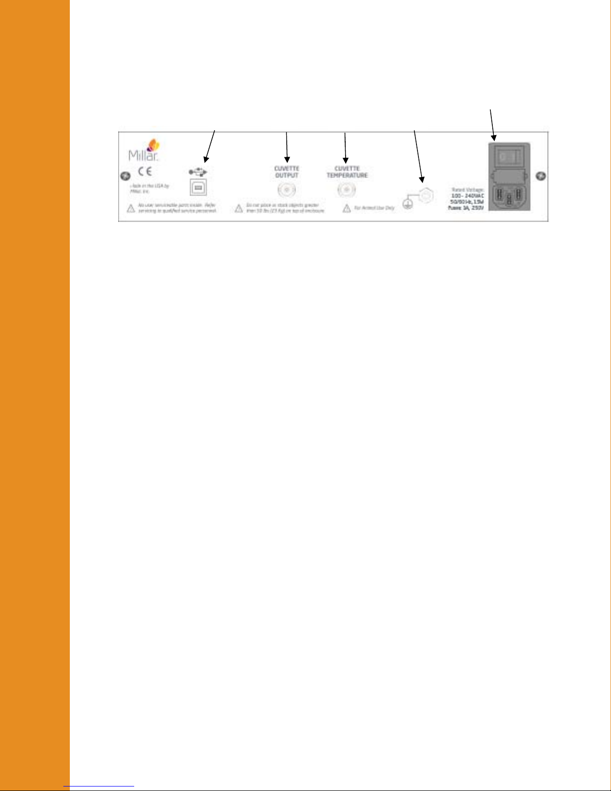
Rear Panel
1. USB Control – The MPVS Ultra system is controlled by the MPVS Ultra Control
Interface software through a USB connection. The system requires a computer
with USB (v1.1) or later. A USB cable is included with the system. Connect the
MPVS Ultra hardware to your computer before turning the computer on. The first
time that a computer is connected to an MPVS Ultra system, software drivers will
be installed; this installation won’t be necessary after the first installation.
2. Cuvette Output – The system is designed to provide a numerical value for the
resistivity measurement using the MPVS Ultra Control Interface. The analog
voltage signal of this measurement is provided on this connection, but users
typically will not use this signal. There is no straightforward conversion between
voltage and resistivity.
3. Cuvette Temperature – The system is designed to provide a numerical value for the
blood temperature using the MPVS Ultra Control Interface so that the user can
choose to correct the resistivity measurement for temperature dependency. The
analog voltage signal of this measurement is provided on this connection, but users
typically will not use this signal in connection with blood sample temperature.
With proper calibration, a user can choose use the temperature input pins on the
front panel Cuvette input (see previous photo) to measure temperature with a
thermodilution catheter. See “Theory of Operation –Temperature Measurement”
for instructions. See “Recommended Accessories” for ordering information for
the particular connector.
4. Equipotential Point (Ground) – The equipotential point or ground post provides a
point at which the user can connect to the system’s analog ground point. The
equipotential point is connected to the ground wire of the power cord. Connecting
the equipotential point to a common ground point with other equipment and
possibly the subject may help reduce noise if signal noise is a problem. Note that
the subject connections and the rho cuvette connections (all analog signal inputs)
are isolated and therefore are not grounded to this point.
5. Universal Power – The system can be powered by 90VAC at 60Hz or 264VAC at
50 Hz. Use the power cord included with your system in North America or
Europe. Power cords for other regions are available through your distributor or
through the source listed in “Recommended Accessories”. See the Technical
Specifications section for more specific information about the power requirements.
Detailed Operation
1 234
5

M.I. P/N 004-2163 Rev. C 13
MPVS Ultra Control Interface
The Control Interface software allows the user to manage catheter configuration, calibrate
all signals, and measure resistivity through an intuitive graphical user interface.
Single-Segment Mode
The MPVS Ultra is shipped from the manufacturer in Single Segment Mode. This mode
only allows for the use of PV catheters with one volume segment such as the PVR-1045
and the SPR-838. A keycode must be entered in order to use the system in Multi-Segment
Mode.
Registration
The Registration Menu allows the user to upgrade a MPVS Ultra Single Segment to the full
Multi-Segment mode. If the user initially purchased the MPVS Ultra with Multi-Segment
capabilities, a keycode will be supplied with the shipment. For information about upgrading
a MPVS Ultra Single Segment unit for use with Multi-Segment PV catheters, please
contact Customer Service.
Export
The Export menu allows the user to save the Catheter Configuration settings for later use in
the PVAN Ultra analysis software. Saving the settings under a recognizable name and
recording the name in the study notes allows the user to load the settings into PVAN Ultra
without having to enter the setting manually.
Catheter Configuration tab
The Catheter Configuration screen allows the user to configure the hardware for
operation with a specific catheter model by setting the appropriate electrode configuration,
choosing the field configuration, excitation current and gain setting. The user can also enter
blood resistivity and alpha for volume calibration.
Detailed Operation

M.I. P/N 004-2163 Rev. C 14
(new screenshot)
Catheter Configuration Locked/Unlocked
This button unlocks and locks the controls on the Catheter Configuration tab in order to
prevent inadvertent changes to the system settings which would affect the
conductance/volume signal as it is being recorded. Click the button once to unlock the
settings.
The catheter configuration must be unlocked before any of the controls on the Catheter
Configuration tab can be adjusted.
The locking feature has a timeout feature which will relock the features after sixty seconds
have passed with no configuration changes.
By default, the catheter configuration used when the program is opened will be the same as
the configuration when the program was last closed.
Millar Catheter Selection
The Millar Catheter Selection table allows the user to load both standard and custom
catheter configurations. This allows the user to configure the hardware for immediate use
based on a known catheter model.
The Millar Catheter Selection table contains several descriptive fields described below.
The table can be sorted by clicking on the desired field name. Click once to sort in
ascending order. Click again to sort in descending order.
Detailed Operation

M.I. P/N 004-2163 Rev. C 15
Name – The Name field is set to Catalog for standard catheter configurations. Users can
select their own name when either editing a catalog catheter or creating their own catheter.
Model Number – This refers to the Millar model number of the catheter. Catheters
modified using the Create New Catheter option retain the model from the catheter from
which they were created. Custom catheters contain a user defined model.
Part Number – This refers to the Millar part number.
Size – Refers to the French size of the catheter. 3F = 1 mm diameter.
ElectrodeNumber – Refers to the number of electrodes on the catheter.
Spacing – Refers to the spacing between sensing electrodes. This spacing is used by the
software when calculating volume from Baan’s equation for calibrating in units of volume
(μl or ml).
Sensor – Describes the location of the pressure sensor(s). The pressure sensor is located
between the listed electrodes. If a pressure sensor is located proximal to all electrodes, its
location will be described as “>E12” or “>E4” as appropriate.
Length – Refers to the length of the catheter from connector to tip.
FieldConfig – Refers to the excitation field configuration of the catheter – single field or
dual field.
ExcitationCurrent – Refers to the excitation current set for this catheter configuration.
SegAmplifierGain – Refers to the chosen gain setting for this catheter configuration.
Blood Resistivity
This feature controls the resistivity used in Baan’s equation for calculating the volume
displayed on the gain and calibration controls within the Control Interface. The values can
also be saved for use in PVAN Ultra. The MPVS Ultra system can measure resistivity
using the rho cuvette (see information regarding the Rho Cuvette tab) or the user can
enter a value for resistivity. Resistivity is used by the software when calculating volume
from Baan’s equation for calibrating in units of volume (μl or ml).
Click Load to recall information used in a previous study. Click Save to save the present
value for later use. The interface allows the user to name the entry.
Unlock the catheter configuration and click Load to load settings from a previous study or
the latest measurement from the rho cuvette.
Alpha (α)
Alpha is an electric field homogeneity factor that allows a user to scale volume
measurements to match independent measurements. This is typically done to make the
stroke volume measurement given by Baan’s equation and the conductance method match
the stroke volume measurement given by thermodilution, ultrasound or flow-probe
measurements. Alpha is saved along with the present blood resistivity value and is used by
the software when calculating volume from Baan’s equation for calibrating in units of
volume (μl or ml).
Graphical Electrode Configuration Control
When a catheter configuration is selected in the Millar Catheter Selection table, the
display in the control will adjust to match the configuration. The user can then adjust the
Detailed Operation

M.I. P/N 004-2163 Rev. C 16
electrode configuration; for example, choosing to use fewer electrodes when measuring a
ventricle whose length does not justify the use of all available electrodes.
There are four electrode states which can be chosen by the user to configure the catheter to
his specification.
1. Inactive – Inactive electrodes are grayed out. These electrodes are not used in generating
or sensing the electric field.
2. Active Sensing – Active sensing electrodes are green. An active sensing electrode
represents one edge of a volume sensing segment.
3. Primary Proximal – Primary electrodes are red. The primary proximal electrode
designates the most proximal edge of the primary electric field. The user can choose to
use any of electrodes 4 – 12 as the primary proximal electrode.
4. Secondary Proximal – Secondary electrodes are orange. The secondary proximal
electrode designates the most proximal edge of the secondary electric field. The user can
choose to use any of electrodes 5 – 11 as the secondary proximal electrode.
Configurations are limited according to the following rules:
1. Electrode 1 must be the primary distal excitation electrode. Only electrode 2 may be
used for secondary distal excitation (but electrode 2 may be used for sensing in a single-
field configuration). See the next section for a description of Field Type.
2. There can be no adjacent inactive electrodes.
3. All active sensing electrodes must be between excitation electrodes.
4. There must be at least two active sensing electrodes.
The green boxes below the catheter graphic label the location of the segments that are
being measured. The labels (S1-S7) correspond to the labels above the connectors on the
front panel of the hardware. When an inactive electrode is located between two active
electrodes, two segments are combined into one segment and two green boxes will have
the same label. The output signal for the resulting double-length segment will be
effectively the sum of the two segments. Be sure to account for this in processing the data.
The system can be configured for one to seven segments.
Field Type
The system can measure conductance with either single field or dual field excitation. This
control determines which is used in the present study. The field configuration of catalog
models is related to the electrode layout. Dual field catheters will have three closely
spaced electrodes at one end (usually the tip) whereas single field catheters have evenly
spaced electrodes. 12-electrode catheters are dual field catheters. Almost any catheter can
be operated in dual- or single-field, but a minimum of six electrodes is required for dual-
field excitation. See “Theory of Operation – Dual Field Excitation” for more information.
The graphical electrode configuration control will reflect the selected field type. The
primary and secondary fields’ excitation currents are illustrated when Dual Field is
selected. Only the primary field’s excitation current is illustrated when Single Field is
selected.
Dual Field mode can only be used with high excitation current.
Detailed Operation

M.I. P/N 004-2163 Rev. C 17
Excitation Current
Catalog models use 20μA for small animal models and 100μA for large animal models.
Either excitation level can be used, regardless of catheter model, but the user is responsible
for determining how much current can be used for smaller animals. Changing the current
setting may require a change in gain setting. If the current is decreased, a larger gain
setting may be required.
Segment Gain-Conductance Range/Segment Gain-Volume Range
The system is capable of measuring the conductance within the ventricle of animals
ranging in size from transgenic mice to domestic livestock. Use the Segment Gain
Conductance (Volume) Range control to make full use of the system’s output range
while keeping the system output from saturating. Choose Conductance Display (blue) or
Volume Display (orange) by clicking on the button to the right of the Segment Gain
Conductance (Volume) Range control. Smaller animals will be measured with lower
gains (e.g., x1) while larger animals will measured with higher gains (e.g., x100). Note the
conductance or volume values to the right of the gain select buttons. The value shown is
the maximum signal that should be measured across all active electrode segments. This
setting affects the available calibration settings on the Catheter Calibration tab.
Show Volume Display/Show Conductance Display
This control will determine whether the guidance values in the Segment Gain
Conductance (Volume) Range control are volume values or conductance values.
Create New Catheter
Use this button to create a new entry in the Millar Catheter Selection table. This is
particularly useful if you regularly use a catheter in a configuration that doesn’t match its
“catalog” entry in the table. Users who purchase a Special model or any other model not
listed on the table may need to add their catheter’s configuration. The Name field can be
used as a descriptive term such as the serial number of the catheter or the experimental
group to which it applies (e.g. “50kg canine”).
Before clicking on the Create New Catheter button, select an existing model that is
similar to the new configuration as possible. Select the appropriate Field Type,
Excitation Current, and Segment Gain Conductance (Volume) Range. Set the
electrode settings on the graphical representation as appropriate. Click Create New
Catheter and fill in the appropriate information. Click OK.
Delete Highlighted Configuration Entry
Use this button to delete non-catalog model catheters from the Millar Catheter Selection
table. Catalog models cannot be deleted.
Power
This indicator will be green when the MPVS Ultra hardware is turned on and red when the
hardware is turned off.
Catheter Detect
This indicator will be green when the catheter is successfully passing the primary
excitation current through the selected electrodes. If the indicator is red, there may be a
problem with the cable or the catheter. Check all connections and see the troubleshooting
section. Current will not pass through the catheter when the catheter is not in a conductive
Detailed Operation

M.I. P/N 004-2163 Rev. C 18
fluid such as blood or saline, so the catheter must be in a conductive fluid to use this
feature.
Catheter Calibration Tab
The Catheter Calibration screen allows the user to electronically calibrate the pressure,
volume, and ECG signals.
Pressure
Balance Locked/Unlocked Button
Use the Balance Locked/Unlocked button to unlock the balance controls.
The button automatically locks after 60 seconds of inactivity within the balance controls
interface.
Pressure 1/Pressure 2
The Pressure 1 and Pressure 2 scales graphically display the currently measured
pressure from −25 mmHg to 200 mmHg.
This number is also numerically displayed. The calculation of the pressure value is based
upon the system’s scale of 1V/100mmHg. The system provides 5V excitation to
transducers assumed to have a sensitivity of 5μV/V/mmHg. (See “Theory of Operation –
Strain Gauge Pressure Transducers.”) The system is designed to use Millar Mikro-Tip®
pressure transducers with 1000 ohms input impedance and 1000 ohms output impedance.
All Millar Mikro-Tip pressure transducers are factory-calibrated to meet these standards.
Detailed Operation

M.I. P/N 004-2163 Rev. C 19
Offset Value (mmHg)
The user can manually adjust the pressure offset of each pressure channel. This is useful
when an artificial offset is introduced into a system and requires correction.
To adjust the pressure offset, unlock the balance controls and use the offset arrows to
manually adjust the offset up or down. The user can also type the desired value directly
into the Offset Value fields. As noted in the procedural descriptions above and in the
transducer IFUs, it is advisable to do this balance adjustment after soaking the catheter for
30 minutes. Ideally, the pressure sensor should be just below the surface of warm (body
temperature) water and shielded from ambient light. See the troubleshooting section for
tips on proper balancing techniques.
The range of the offset is −250 mmHg to 250 mmHg.
The balance control does not affect the electronic calibration outputs (0mmHg, 25mmHg,
and 100mmHg) described below.
Auto Zero
The user can quickly auto zero each pressure channel by applying a zero reference pressure
to the catheter and then clicking Auto Zero under the desired channel. This sets the
applied pressure as zero.
Pressure 2 Select
The MPVS Ultra provides two amplifiers for use with a pressure transducer.
Pressure 1 is always set to the P-V input connector on the MPVS Ultra front panel. This
will typically be the pressure sensor located in the middle of the conductance electrodes.
Pressure 2 Select allows the user to specify which input is used for the secondary
pressure channel.
Primary (P-V) sets the second pressure input to the P-V input connector on the MPVS
Ultra front panel. This is used when the user is using a dual sensor pressure volume
catheter such as the SPR-562-1.
Secondary (P2) sets the second pressure input to the P2 input connector on the MPVS
Ultra front panel. This is used when the user is using a separate single sensor pressure
catheter.
Pressure Monitor and Calibration
Transducer – When the Transducer button is activated the system will read inputs from
the pressure sensors. The Transducer button must be activated to view pressure
waveforms.
0 mmHg – When the 0 mmHg button is activated, the MPVS Ultra will output a zero volt
signal to both pressure outputs.
25 mmHg – When the 25 mmHg button is activated, the MPVS Ultra will output a 0.25
V signal to both pressure outputs.
100 mmHg – When the 100 mmHg button is activated, the MPVS Ultra will output a 1.0
V signal to both pressure outputs.
Detailed Operation

M.I. P/N 004-2163 Rev. C 20
Volume
Display Conductance/Volume Units
Use this button to change the display to conductance or volume units as desired. This
button does not affect the output voltage.
Measured Volume
This display indicates the current composite volume as measured by the MPVS Ultra. The
value displayed is based upon an analog summation of all active segments. This analog
sum is the COMPOSITE output on the front panel.
The blue or orange scale is a graphical representation of the composite volume signal.
When the user opts to view units of volume (μl or ml), the calculation of this value takes
into account segment length, rho and alpha chosen on the Catheter Configuration tab.
The output shown in the MPVS Ultra Control interface does not account for the volume
attributed to parallel conductance of the myocardium. If desired, this correction can be
made in the PVAN Ultra software or the user’s acquisition software.
Transducer and Electronic Calibration Buttons
The active button is green. To measure a volume signal from the catheter, click the
Transducer button.
In order to calibrate the data acquisition system from voltage to volume or conductance
units, the system has six internal sets of resistors that are used as inputs of known
conductance. Only two to three buttons are available at any given gain range. (Available
buttons are beige; others are gray.) The available selections are designed to span the
expected segmental conductance inputs for typical animals ranging from mice to domestic
livestock. The gain setting on the Catheter Configuration tab controls the available input
range in order to maximize the use of the available voltage output range. The indicated
values on the buttons are the conductance or volume to be output by each segment, not the
composite total.
The values indicated on the calibration buttons change according to the present
configuration. When volume units are displayed, Baan’s equation is used, so the present
values of alpha, rho, and segment length are used, as noted in Measured Volume above.
Since the values on the buttons represent the per-segment conductance or volume, be sure
to multiply by the number of active segments when entering the calibration value for the
Composite Volume channel. The Composite Volume or Composite Conductance value is
displayed by the software when one of the calibration buttons is pressed.
ECG Calibration
The ECG Calibration interface allows the user to generate a calibration signal for the ECG
output, control the source of the signal, and enable or disable the notch filter.
Current Value
The numerical readout displays the current ECG signal measured by the MPVS Ultra.
ECG Scale
The ECG Scale graphically displays the current ECG signal measured by the MPVS Ultra.
Detailed Operation
Table of contents
Popular Laboratory Equipment manuals by other brands

Gilson
Gilson PLATEMASTER P20 user guide

Micromeritics
Micromeritics SediGraph III 5120 Installation Instructions and Checklist

Cognex
Cognex DataMan 70 Series Quick reference guide

RADWAG
RADWAG MAC Series user manual

Velp Scientifica
Velp Scientifica AREX 5 instruction manual

PSI
PSI AlgaeTron Manual and user guide

Applied Biosystems
Applied Biosystems 7500 Getting started

Sartorius stedim
Sartorius stedim Sartocube ECO Series user manual

EG
EG Xcellerex XDUO 2500 operating instructions

Digitus
Digitus DN-651141 Quick installation guide

TP-Link
TP-Link Omada POE160S installation guide

PASCO
PASCO ME-9430 Instruction manual and experiment guide


