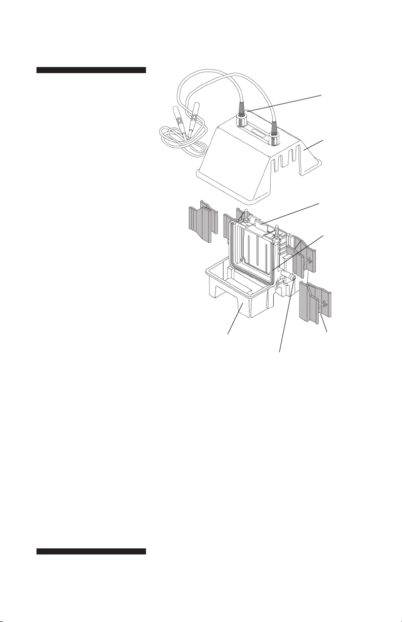
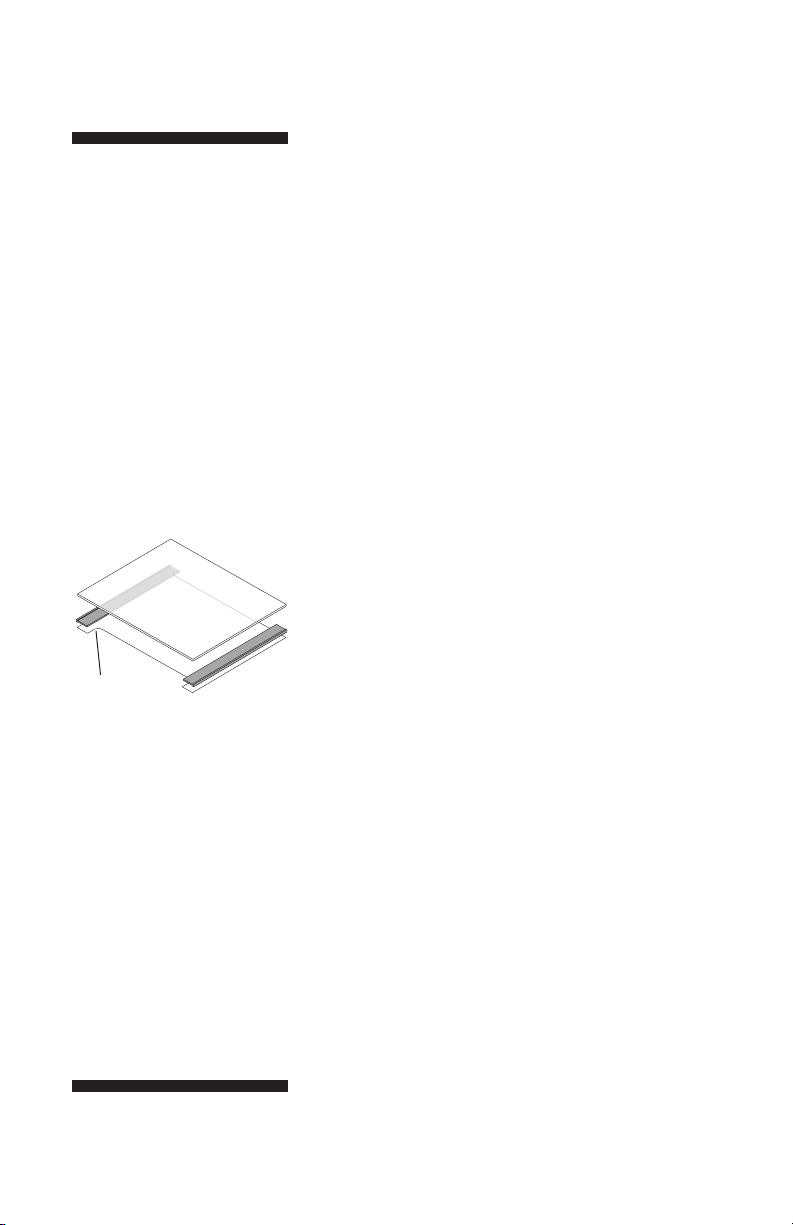
Hoefer SE 260 User manual

user manual
SE 260
um SE260-IM/Rev. A0/05-04
Hoefer SE 260
mini-vertical gel electrophoresis unit


Page finder
1. Gel Electrophoresis Unit Function . . . . . . . . . . . 1
and Description
2. Important information . . . . . . . . . . . . . . . . . . . . 4
3. Operating instructions . . . . . . . . . . . . . . . . . . . . 6
4. Care and maintenance . . . . . . . . . . . . . . . . . . 16
5. Troubleshooting . . . . . . . . . . . . . . . . . . . . . . . 17
Appendix
Bibliography . . . . . . . . . . . . . . . . . . . . . . . . . . . 21
• pi

• pii

1. Gel Electrophoresis Unit
Function and Description
The Hoefer™ SE 260 small format vertical slab
gel unit is intended for rapid electrophoresis of
protein or nucleic acid samples. Most samples
can be run in as little as 45 minutes, and only a
minimal amount of sample is required.
The SE 260 accommodates one or two 10 × 8 cm
or 10 × 10.5 cm gel sandwiches. The upper
buffer chamber is formed when the notched side
of a gel sandwich is sealed against the silicone
rubber gasket. The upper buffer chamber core
serves as a heat exchanger if cooling is required.
The core is hollow and equipped with ports on
either side for coolant circulation.
Unpacking
Unwrap all packages carefully and compare
contents with the packing list, making sure all
items arrived. If any part is missing, contact
your local sales office. Inspect all components
for damage that may have occurred while the
unit was in transit. If any part appears damaged,
contact the carrier immediately. Be sure to keep
all packing material for damage claims or to use
should it become necessary to return the unit.
• p1

• p2
This declaration of
conformity is only valid for
the instrument when it is:
• used in laboratory locations,
• used as delivered from
Hoefer, Inc. except for alter-
ations described in the user
manual, and
• connected to other
CE-labeled instruments
or products recommended
or approved by Hoefer, Inc.
Specifications
Gel plate size 10 × 10.5 cm
Approximate gel size 8 × 9.5 cm
Max. wattage 12 W
Max. voltage 500 V
Max. amperage 500 mA
Max. temperature 45 °C
Environmental Indoor use: 4–40 °C
operating conditions Humidity up to 80%
Altitude up to 2000 m
Installation category II
Pollution degree II
Dimensions (w × h × d) 16.5 × 18 × 16 cm
(6.5 × 7.1 × 6.3 in.)
Product certifications EN61010–1, UL61010A–1,
CSA C22.2 1010.1,
CE Certified

• p3
Color-coded
leads (2)
SE6056-HV
Safety lid
SE256
SE 260 Lower
buffer chamber
SE255D
Upper buffer
chamber core
SE254B
Spring clamps (4)
SE252
Coolant port (2)
Foam gasket
SE208
Fig 1. Main components SE 260
electrophoresis unit
Included but not shown:
Glass plates
Notched alumina plates
Gel seal, 1/4 oz.
Spacer-Mate
Well-locating decal
Required but not included:
Power supply with a
minimum rating: 250 V,
50 mA, constant current or
constant voltage

• p4
2. Important information
• The safety lid must be in place before connecting
the power leads to a power supply.
• Turn all power supply controls off and disconnect
the power leads before removing the safety lid.
• Circulate only water or 50/50 water/ethylene glycol
through the heat exchanger. Never introduce anti-
freeze or any organic solvent into any part of the
instrument. Organic solvents will cause irreparable
damage to the unit!
• Do not connect the heat exchanger to a water tap
or any coolant source where the water pressure is
unregulated.
• Do not operate with buffer temperature above 45
°C. All plastic parts are rated for 45 °C continuous
duty. Circulate coolant through the heat exchanger
during electrophoresis to minimize heating. Addi-
tional passive cooling actions include chilling the
buffer before use, running the unit in a cold room,
or both. Overheating will cause irreparable damage
to the unit!
• If running only one gel, block off the unused part
of the core with a glass plate. Do not fill this side
with buffer.
• Only accessories and parts approved or supplied by
Hoefer, Inc. may be used for operating, maintaining,
and servicing this product.
English
�
�

Informations importantes
• Le couvercle de sécurité doit être en place avant de
brancher les prises au générateur.
• Eteindre le générateur et débrancher les prises
avant d’enlever le couvercle de sécurité.
• Faire circuler seulement de l’eau ou 50/50 d’eau
et d’éthylène glycol dans l’échangeur vertical à
cirulation d’eau. Ne jamais utiliser d’anti-gel ou
tout autre solvant organique avec cet instrument.
Les solvants organiques causeraient des dommages
irréparables à l’appareil.
• Ne pas connecter l’échangeur vertical à circulation
d’eau à un robinet ou quelque source de refroidisse-
ment dont la pression n’est pas régulière.
• Ne pas utiliser avec un tampon à une température
au dessus de 45 °C. Toutes les piéces en plas-
tique sont prévues pour résister à une température
constante de 45 °C. Faire circuler l’eau dans
l’échangeur vertical durant l’électrophorèse pour
minimiser l’échauffement. L’on peu aussi refroidir le
tampon avant l’utilisation et/ou utiliser l’instrument
dans une chambre froide. Un surchauffement peut
causer des dommages irréparables à l’instrument.
• Pour le coulage d’un seul gel, bloquer la parite de la
chambre non utilisée avec une plaque de verre. Ne
pas remplir le côté vide avec du tampon.
• Seulement les accessoires et piéces detachées
approuvés ou fournis par Hoefer, Inc. sont recom-
mandés pour l’utilisation, l’entretien et réparation
de cet appareil.
Français
�
�
• p5

• p6
3. Operating instructions
3.1 Prepare the gel sandwich
Both precast and self-cast gels can be run in the
SE 260 units. For longer gel length, 10 × 10.5 cm
plates, gels can be cast in the Hoefer SE 235
4-gel caster. The SE 260 can also accommodate
shorter length gel in 10 × 8 cm plates, which can
be cast in a Hoefer SE 215, SE 245, or SE 275
gel caster.
Each unit includes notched alumina plates and
rectangular glass plates. If casting your own
polyacrylamide gels, we recommend using a
notched alumina ceramic back plate because it
transfers heat 40 times more rapidly than glass.
For applications that are not heat sensitive, a
notched glass plate is available.
Before loading gels into the electrophoresis unit,
the separating gel should already be completely
polymerized. Clean away any gel adhering to the
alumina back plate. The stacking gel (if appli-
cable) can be cast in place on the electrophoresis
unit. Load liquid samples after the gel sandwich
is installed.
Notched plate
Note: All electrophoresis
accessories and kits are listed
in the the ordering section.
Note: Inspect glass plates
for chipped edges. Use only
unchipped plates to prevent
leaking.

3.2 Prepare the unit
To disassemble a fully assembled unit: Remove the
safety lid by pressing on the handle at the top of the
upper buffer chamber core while lifting the lid by the
bottom edges. Empty all buffer chambers and remove
any gel sandwiches. Then depress both release tabs
and lift out the upper buffer chamber core.
Rinse the instrument before each use. Before using the
first time, disassemble the unit completely and wash
with a dilute solution of a laboratory detergent and
thoroughly rinse with water and distilled water.
Check the gasket. Periodically remove the gray silicone
rubber gasket from the core. Inspect for nicks and
wear. If the gasket appears to be intact, apply a light
film of Gel seal, and replace it in the groove. Avoid
stretching the gasket by laying it onto the groove and
pressing it into place.
Optional cooling.
Circulating pressure must not exceed 0.8 bar (12 psi)
above ambient pressure. Do not connect the cooling core
to an unregulated coolant source such as a water tap.
Connect the cooling core to a circulator bath such
as the MultiTemp III. Slide hose clamps (4 total)
onto each end of two lengths of 8 mm (5/16”) vinyl
or silicone tubing. Attach one end of each length of
tubing to a cooling core port. Attach the free ends of
each length of tubing to the circulator bath ports; one
to the inlet and the other to the outlet. Secure the
connections with the hose clamps.
• p7
Important! Use only water
or water and ≤50% ethylene
glycol as a coolant. Do not use
a commercial antifreeze or any
alcohol-based mixture.
Note: If the cooling option is
used frequently, it is conve-
nient to attach QuickFit
connectors to the tubing.
The valves in these fittings
prevent coolant spillage.

• p8
Fig 2. Core installation
and removal.
Install the upper buffer chamber core. First steady the
lower chamber with one hand and then hold the core
with the other hand, position it on the positioning
tabs, and press down, listening for the core to snap
into place. (Alternatively, depress both release tabs at
either side, position the core on the positioning tabs,
press into place, and release the tabs. Check that the
core is secure.)
To remove the core,
depress both release
tabs and lift.
To install the core, position it over the
positioning tabs. Then either press
down, listening for the core to snap
into place
—OR —
depress both release tabs, set the core
in place, and release.
Handle
Release tabs (2)
Coolant port (2)

3.3 Place the gel sandwich
Rinse away the overlay with distilled water and drain
any excess water.
If installing a self-cast or precast 10 × 8 cm gel sand-
wich, align the bottom of the plate with the bottom
of the core. (Fig. 3a) The bottom of the notched plate
must cover the silicone rubber gasket.
If installing a self-cast or precast 10 × 10.5 cm gel
sandwich, orient the sandwich so that the notched
plate faces the gasket, notches at the top. Set the
bottom of the sandwich on the supporting ledges in
the bottom of the lower chamber and center the plate
so that the gasket seals both sides. (Fig. 3b)
Fig. 3a–b. Gel sandwich
installation.
• p9
Fig 3a. A 10 × 8 cm gel sandwich
fits flush with the bottom of the
upper buffer chamber core.
Fig 3b. A 10 × 10.5 cm gel sand-
wich fits against the bottom of the
lower buffer chamber.

• p10
Clamp the sandwich in place
Lightly press the sandwich against the gasket and
secure it to the core with one spring clamp on each
side. Position the jaw so that the shorter rounded jaw
edge fits into the core groove and the longer edge sits
on the glass plate. (Proper positioning is important to
achieve a seal and to minimize glass breakage.) Slide
the clamps down to the stop.
Repeat step 1 for the second sandwich, or, if running
only one gel, clamp a plain glass plate on the unused
side of the core to prevent a possible short circuit
with the unused electrode. (Do not fill this chamber
with buffer if no gel sandwich is in place.)
Fit short jaw of clamp
into the groove
Cooling is optional:
Attach tubing to ports on
both sides of the core before
attaching gel sandwiches.
Circulate coolant.
Fig 4. Securing the gel
sandwich onto the upper buffer
chamber core
Each sandwich requires two
clamps. The rounded edge of the
short jaw on the clamp fits into
the groove behind the gasket, and
the long jaw presses on the glass
plate over the spacer.

3.4 Sample preparation and loading
If wells are already in place, skip to step 2.
If applicable, cast the stacking gel in the unit.
Calculate the stacking gel monomer solution volume:
measure the distance, in cm, from the top of the
resolving gel to the notch in the alumina plate. (This
should be at least 2 cm—more if the sample depth
in the well is unusually high.) Multiply this distance
by the gel width (8.3 cm) and the gel thickness (cm).
This product is the required volume in ml.
Deaerate the stacking gel monomer solution, add
catalyst and initiator and then pour. Use a pipette
to deliver the solution into one corner of the plate,
taking care not to trap any bubbles. Insert a comb (at
a slight angle to prevent trapping air) into the sand-
wich, allowing the comb sides to rest on the spacers.
Prepare the sample. Increase liquid sample density
with 10% glycerol or sucrose. Add a tracking dye such
as phenol red or bromophenol blue.
For SDS protein gels, use 2X treatment buffer to
denature both liquid and dry samples in a test tube.
To liquid protein solutions, add an equal volume of 2X
buffer. To dry protein samples, add equal volumes of
buffer and ddH2O to achieve the desired concentra-
tion. Heat the tube in boiling water for 90 seconds,
then chill it in ice until ready to use. Treated samples
can be stored frozen for future runs. (Store at -40 °C
to -80 °C.)
To aid in loading samples, wet the well-locating decal
and apply it to the front of the glass plate so that the
appropriate edge outlines the sample wells.
Note: The side wells for standards of a preparative
comb correspond to the outer-most wells formed by
the 10-well comb.
• p11
Note: Stacking gel resolution
is optimal when poured just
before electrophoresis.

• p12
Note: The amount of protein
sample added to each well
depends on both the sensitiv-
ity of the staining method
and the distribution of protein
among separate bands. With
Coomassie™ Blue, it is possi-
ble to detect 1 µg in a single
band; with the more sensitive
silver stains, it is possible to
detect as little as 10 ng.
Fill the sample wells and each upper buffer cham-
ber that will be used with running buffer. One upper
buffer chamber holds approximately 75 mL.
Underlay the sample into the wells using a fine-tipped
microsyringe. The width of the wells depends on the
number of wells per comb. If the comb has fewer
wells, they are wider, and require more volume to
raise the level 1 mm, as shown in the following table.
Volume of sample (µL) per 1 mm depth
no. of vcomb thickness (mm)
wells
0.75 1.0 1.5
5 9.5 12.7 19.1
9 5.8
10 3.6 4.8 7.2
15 2.2 2.9 4.4
18 2.9

3.5 Final assembly
Fill the lower buffer chamber with running buffer. The
SE 260 holds about 250 mL. Check that the lower
electrode (running along the bottom of the the upper
buffer chamber core) is completely submerged.
Note: If using precast gels, check that the lower gel/
buffer contact surface is exposed (the colored plastic
tape must be removed.)
Place the safety lid on the unit.
Plug the color-coded leads into the jacks of an
approved power supply such as the EPS 2A200. The
red lead plugs into the red output jack, and the black
lead plugs into the black output jack.
Optional cooling: Begin circulating cold water or a
chilled 50/50 water/ethylene glycol solution.
• p13
Important! Do not use anti-
freeze or any alcohol-based
mixture, as these will irrepara-
bly damage the core.

• p14
Important! After initial moni-
toring, do not leave the unit
unattended for more than
45 minutes before checking
the progress of the the bands
and the buffer level.
3.6 Running the Gel
Gels may be run at either constant current or
constant voltage. A constant current setting is
traditionally used with a discontinuous buffer
system so that the rate of electrophoretic migra-
tion remains unchanged throughout the run.
Under these conditions, voltage increases as the
run proceeds. A lower current setting is recom-
mended for higher resolution. Precast gels are
run under the same current and voltage condi-
tions as self-cast gels.
It takes about one hour to run two 7 cm ×
0.75 mm Laemmli gels at 40 mA (20 mA per gel,
constant current). Check band progress after
5 minutes, and again after half an hour, keeping
an eye on the position of the tracking dye. The
run is complete when the tracking dye reaches
the bottom of the gel. Watch the buffer level
in the upper buffer chamber and, if necessary,
replenish it before it falls below the level of the
notched plate. (A small volume of buffer may
leak past a chipped plate or nicked gasket, or it
may wick out through the gel.)

After the run
Once the tracking dye reaches the bottom of the gel,
turn off the power supply, disconnect the leads, and
remove the safety lid.
If coolant is circulating, stop the flow and disconnect
the fittings or tubing.
Remove the core assembly with gels attached by squeez-
ing the release tabs and lift out the core assembly.
Pour out the buffer by inverting the core assem-
bly, then remove both clamps, and lift away gel
sandwich(es) from the upper buffer chamber core.
Gently loosen and then slide away both spacers. Slip an
extra spacer or a Hoefer Wonder Wedge into the bottom
edge (to prevent breaking the ears of the notched
plates) and separate the plates. The gel usually adheres
to the alumina plate. Carefully lift the gel from the plate
and lay it into a tray of stain or fixative.
Important! Always disconnect
the high voltage leads from the
power supply before removing
the lid from the unit.
• p15

• p16
4. Care and maintenance
• Do not autoclave or heat any part above 45 °C.
• Do not use organic solvents, abrasives, strong
cleaning solutions, or strong acids or bases to
clean the chambers.
Immediately after each use, rinse the unit with
water and then rinse thoroughly with distilled
water. Handle the upper buffer chamber core
with care to prevent damage to the banana
plugs. Allow to air dry.
Clean glass and alumina plates and spacers with
a dilute solution of a laboratory cleanser such
as RBS-35™, then rinse thoroughly with tap and
distilled water. Glass plates can also be treated
with (but not stored in) acid cleaning solutions.
Table of contents
Other Hoefer Laboratory Equipment manuals

Hoefer
Hoefer SG15 User manual

Hoefer
Hoefer UVC5000 User manual

Hoefer
Hoefer HB1000 User manual

Hoefer
Hoefer SG500 User manual

Hoefer
Hoefer TE70X User manual

Hoefer
Hoefer TE 22 User manual

Hoefer
Hoefer MacroVue UV-25 User manual

Hoefer
Hoefer SE 400 User manual

Hoefer
Hoefer TE 70 User manual

Hoefer
Hoefer HE99X User manual
Popular Laboratory Equipment manuals by other brands

Leica
Leica EM TXP operating manual

Molecular Devices
Molecular Devices SpectraMax M3 user guide

Sartorius
Sartorius Midi Plus quick start guide

Pall
Pall WandMixer RDUA003A Operator's manual

Santai Technologies
Santai Technologies SepaBean Hardware manual

Hamamatsu
Hamamatsu Energetiq LDTLS TLS-EQ-9 Operation manual