Millipore Tylan General FC-2900 User manual
INSTRUCTION
MANUAL
FC-2900
SERIES
Mass
Flow
Controllers
and
Flowmeters
Wan
General
Mass
Flow
Controllers
FC-2900,
FC-29000,
FC-2901,
FC-29010,
FC-2902,
FC-29020
FC-2910,
FC-29100,
FC-2911,
FC-29110,
FC-2912,
FC-29120
FC-2900B,
FC-2900BO,
FC-2910B,
FC-2910BO
FC-2900M,
FC-2900MO,
FC-2901M,
FC-2901MO,
FC-2902M,
FC-2902MO
Mass
Flowmeters
FM-3900,
FM-3901,
FM-3902
FM-3910,
FM-3911,
FM-3912
FM-3900M,
FM-3901M,
FM-3902M
JUNE
1997

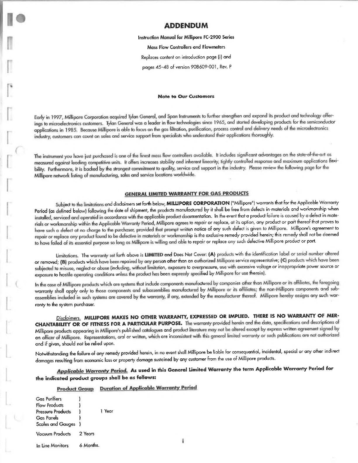
ADDENDUM
Instruction
Manual
for
Millipore
FC-2900
Series
Mass
Flow
Controllers
and
Flowmeters
Replaces
content
on
introduction
page
(i)
and
pages
45-48
of
version
908609-001,
Rev.
P
Note
to
Our
Customers
Early
in
1997,
Millipore
Corporation
acquired
Tylan
General,
and
Span
Instruments
to
further
strengthen
and
expand
its
product
and
technology
offer-
ings
to
microelectronics
customers.
Tylan
General
was
a
leader
in
flow
technologies
since
1965,
and
started
developing
products
for
the
semiconductor
applications
in
1985.
Because
Millipore
is
able
to
focus
on
the
gas
filtration,
purification,
process
control
and
delivery
needs
of
the
microelectronics
industry,
customers
can
count
on
sales
and
service
support
from
specialists
who
understand
their
applications
thoroughly,
The
instrument
you
have
just
purchased
is
one
of
the
finest
mass
flow
controllers
available.
It
includes
significant
advantages
on
the
state-of-the-art
as
measured
against
leading
competitive
units.
It
offers
increases
stability
and
inherent
linearity,
tightly
controlled
response
and
maximum
applications
flexi-
bility.
Furthermore,
it
is
backed
by
the
strongest
commitment
fo
quality,
service
and
support
in
the
industry.
Please
review
the
following
page
for
the
Millipore
network
listing
of
manufacturing,
sales
and
service
locations
worldwide.
GENERAL
LIMITED
WARRANTY
FOR
GAS
PRODUCTS
Subject
to
the
limitations
and
disclaimers
set
forth
below,
MILLIPORE
CORPORATION
("Millipore")
warrants
that
for
the
Applicable
Warranty
Period
(as
defined
below)
following
the
date
of
shipment,
the
products
manufactured
by
it
shall
be
free
from
defects
in-materials
and
workmanship
when
installed,
serviced
and
operated
in
accordance
with
the
applicable
product
documentation.
In
the
event
that
a
product
failure
is
caused
by
a
defect
in
mate-
rials
or
workmanship
within
the
Applicable
Warranty
Period,
Millipore
agrees
to
repair
or
replace,
at
its
option,
any
product
or
part
thereof
that
proves
to
have
such
a
defect
at
no
charge
to
the
purchaser,
provided
that
prompt
written
notice
of
any
such
defect
is
given
to
Millipore.
Millipore's
agreement
to
repair
or
replace
any
product
found
to
be
defective
in
materials
or
workmanship
is
the
exclusive
remedy
provided
herein;
this
remedy
shall
not
be
deemed
to
have
failed
of
its
essential
purpose
so
long
as
Millipore
is
willing
and
able
to
repair
or
replace
any
such
defective
Millipore
product
or
part.
Limitations.
The
warranty
set
forth
above
is
LIMITED
and
Does
Not
Cover:
(A)
products
with
the
identification
label
or
serial
number
altered
or
removed;
(B)
products
which
have
been
repaired
by
any
person
other
than
an
authorized
Millipore
service
representative;
(C)
products
which
have
been
subjected
to
misuse,
neglect
or
abuse
(including,
without
limitation,
exposure
to
overpressure,
use
with
excessive
voltage
or
inappropriate
power
source
or
exposure
to
hostile
operating
conditions
unless
the
product
has
been
expressly
specified
by
Millipore
for
use
therein).
In
the
case
of
Millipore
products
which
are
systems
that
include
components
manufactured
by
companies
other
than
Millipore
or
its
affiliates,
the
foregoing
warranty
shall
apply
only
to
those
components
and
subassemblies
manufactured
by
Millipore
or
its
affiliates;
the
non-Millipore
components
and
sub-
assemblies
included
in
such
systems
are
covered
by
the
warranty,
if
any,
extended
by
the
manufacturer
thereof.
Millipore
hereby
assigns
any
such
war-
ranty
to
the
system
purchaser.
Disclaimers.
MILLIPORE
MAKES
NO
OTHER
WARRANTY,
EXPRESSED
OR
IMPLIED.
THERE
I$
NO
WARRANTY
OF
MER-
CHANTABILITY
OR
OF
FITNESS
FOR
A
PARTICULAR
PURPOSE.
The
warranty
provided
herein
and
the
data,
specifications
and
descriptions
of
Millipore
products
appearing
in
Millipore's
published
catalogues
and
product
literature
may
not
be
altered
except
by
express
written
agreement
signed
by
an
officer
of
Millipore.
Representations,
oral
or
written,
which
are
inconsistent
with
this
general
limited
warranty
or
such
publications
are
not
authorized
and
if
given,
should
not
be
relied
upon.
Notwithstanding
the
failure
of
any
remedy
provided
herein,
in
no
event
shall
Millipore
be
liable
for
consequential,
incidental,
special
or
any
other
indirect
damages
resulting
from
economic
loss
or
property
damage
sustained
by
any
customer
from
the
use
of
Millipore
products.
Applicable
Warranty
Period.
As
used
in
this
General
Limited
Warranty
the
term
Applicable
Warranty
Period
for
the
indicated
product
groups
shall
be
as
follows:
Product
Group
Duration
of
Applicable
Warranty
Period
Gas
Purifiers
)
Flow
Products
)
Pressure
Products
}
1
Year
Gas
Panels
)
Scoles
and
Gouges
)
Vacuum
Products
2
Years
In
Line
Monitors
6
Months.
To
Place
an
Order
or
Receive
Technical
Assistance
For
additional
information
call
your
nearest
Millipore
office:
In
the
U.S.
and
Canada,
call
tollfree
1-800-MILLIPORE
(1-800-645-5476)
In
the
U.S.,
Canada
and
Puerto
Rico,
fax
orders
to
1-800-MILLIFX
(1-800-645-5439)
Find
the
latest
catalog,
data
sheets
and
technical
briefs
at
www.tmillipore.com
E-mail:
Millipore
Worldwide
AUSTRALIA
Tel.
1
800
222
111
or
(02)
9888
8999
Fax
(02)
9878
0788
AUSTRIA
Tel.
01
50
22
21
237
Fox
01
50
22
21
238
BELGIUM
Tel.
02
64
04
185
Fox
02
64
68
096
BRAZIL
Tel.
(011)
5487011
Fax
|011)
548-7923
CHINA,
PEOPLE’S
REPUBLIC
OF
Beijing:
Tel.
(8610)
6500-8063
Fax
(8610)
65007372
Guangzhou:
Tel.
(8620)
8755-4021
Fax
(8620)
8755-4350
Hong
Kong:
Tel.
(852)
2803-9111
Fox
(852)
2513-0313
Shanghai:
Tel.
(8621)
53069100
Fax
(8621)
53060838
CZECH
REPUBLIC
Tel.
02-205
138
41
02-205
138
42
Fax
02-205
14294
DENMARK
Tel.
3525
0275
Fox
3525
0276
FINLAND
Tel.
09
8171
0010
Fax
09
8171
0011
FRANCE
Tel.
01
30
1271
50
Fax
01
30
12
71
84
GERMANY
Tel.
0816
595
110
Fox
0816
561
399
INDIA
Tel.
91}
80839
46 57
Fax
(91)
80839
63
45
IRELAND
Tel.
01
799
7165
Fax
01
799
7166
ITALY
Tel.
02
21
50
488
Fax
02
26
41
06
79
JAPAN
Tel.
(03)
54429711
Fax
(03)
5442-9738
KOREA
Tel,
(822)
551-0990
Fox
(822)
5510227
MALAYSIA
Tel.
603-757
1322
Fox
603-757
1711
MEXICO
Tel.
(525)
576-9688
Fax
(525)
576-8706
THE
NETHERLANDS
Tel.
020
65
45
226
Fax
020
65
45
227
NORWAY
Tel.
22
59
5888
Fax
22
59
5889
POLAND
Tel.
(49)
816
595
110
Fox
(49)
816
561
399
RUSSIA
Tel.
(49)
816
595
110
Fox
(49)
816
561
399
SINGAPORE
Tel.
(65)
842
1822
Fox
(65)
842
4988
SPAIN
Tel.
091
375
33
81
Fox
091
375
33
82
SWEDEN
Tel.
08
5199
2040
Fox
08
5199
2041
SWITZERLAND
French-speaking:
Tel.
022
82
30
450
Fax
022
82
30
491
German-speaking:
Tel.
01
43 95
356
Fax
01
43 95
355
TAIWAN
Toipei:
Tel.
(886-2)
700-1742
Fox
(886-2)
755-3267
Hsin
Chu
City:
Tel.
(886-3)
571-0178
Fax
[886-3]
572-9520
U.K.
Tel.
0179
361
5808
Fax
0179
361
7442
U.S.A.
AND
CANADA
Tel.
800
645
5476
Fax
800 645
5439
OTHER
COUNTRIES
Millipore
Intertech
(U.S.A.]
Tel.+1
(781)
533-8622
Fax
+1
(781)
533-8630
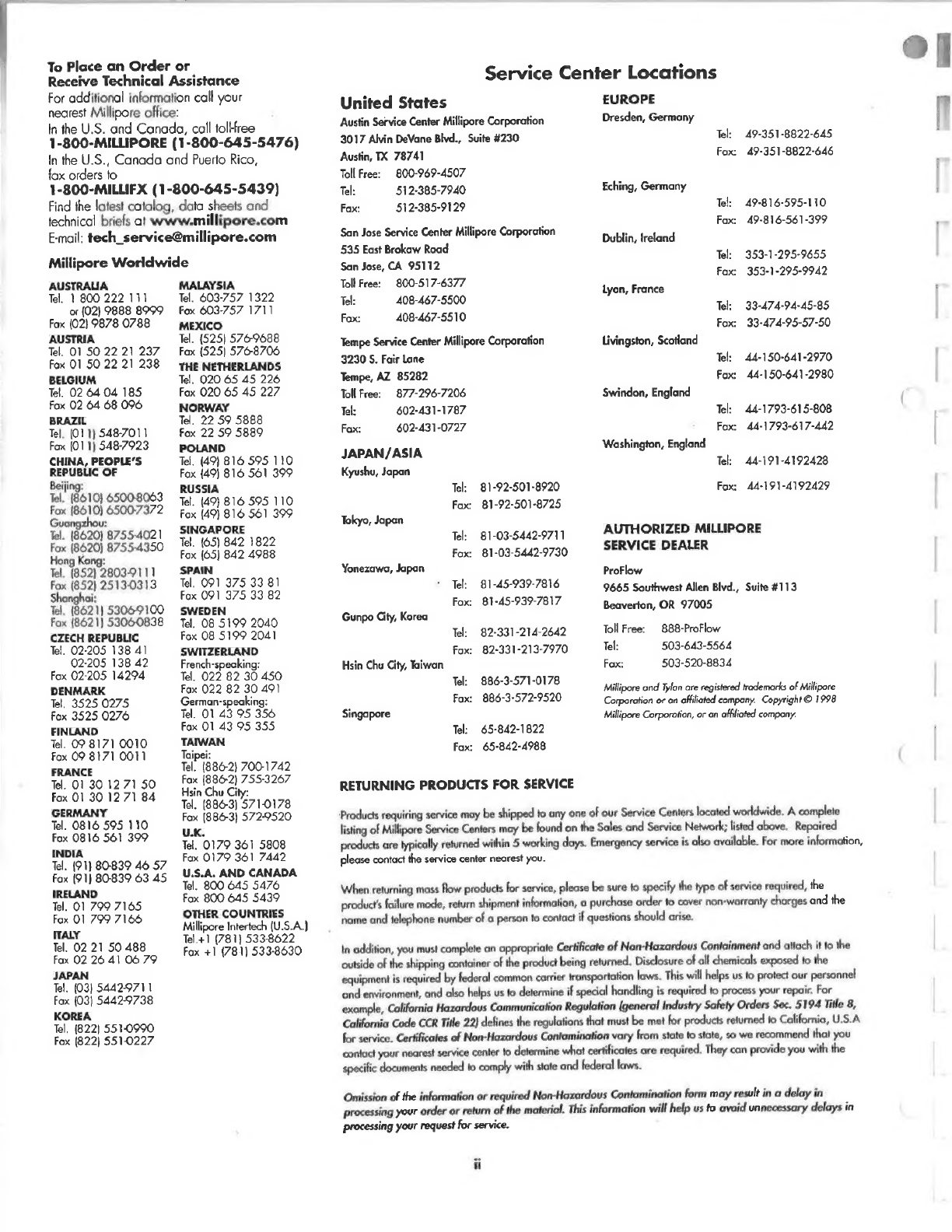
Service
Center
Locations
United
States
Austin
Service
Center
Millipore
Corporation
3017
Alvin
DeVane
Blvd.,
Suite
4230
Austin,
TX
78741
Toll
Free:
800-969-4507
Tel:
512-385-7940
Fax:
512-385-9129
San
Jose
Service
Center
Millipore
Corporation
535
East
Brokaw
Road
San
Jose,
CA
95112
Toll
Free:
800-517-6377
Tel:
408-467-5500
Fax:
408-467-5510
Tempe
Service
Center
Millipore
Corporation
3230
S.
Fair
Lane
Tempe,
AZ
85282
Toll
Free:
—
877-296-7206
Tel:
602-431-1787
Fax:
602-431-0727
JAPAN/ASIA
Kyushu,
Japan
Tel:
81-92-501-8920
Fax
81-92-501-8725
Tokyo,
Japan
Те:
81-03-5442-9711
Fox:
81-03-5442-9730
Yonezawa,
Japan
Те:
81-45-939-7816
Fox:
81-45-939-7817
Gunpo
City,
Korea
Те:
82-331-214-2642
Fax:
82-331-213-7970
Hsin
Chu
City,
Taiwan
Tel:
886-3-571-0178
Fox:
886-3-572-9520
Singapore
Tek
65-842-1822
Fax:
65-842-4988
RETURNING
PRODUCTS
FOR
SERVICE
EUROPE
Dresden,
Germany
Tel:
49-351-8822-645
Fax:
49-351-8822-646
Eching,
Germany
Tek
49-816-595-110
Fox:
49-816-561-399
Dublin,
Ireland
Tel:
353-1-295-9455
fax
353-1-295-9942
Lyon,
France
Те:
33-474-94-45-85
Ғох:
33-474-95-57-50
Livingston,
Scotland
Tel:
44-150-641-2970
Fax:
44-150-641-2980
Swindon,
England
Tel:
44-1793-615-808
Fox:
44-1793-617-442
Washington,
England
Те:
44-191-4192428
Ғох:
44-191-4192429
AUTHORIZED
MILLIPORE
SERVICE
DEALER
ProFlow
9665
Southwest
Allen
Blvd.,
Suite
#113
Beaverton,
OR
97005
Toll
Free:
888-ProFlow
Tel:
503-643-5564
Fax:
503-520-8834
Millipore
and
Tylon
are
registered
trademarks
of
Millipore
Corporation
or
an
affiliated
company.
Copyright
©
1998
Millipore
Corporation,
or
an
affiliated
company.
‘Products
requiring
service
may
be
shipped
to
any
one
of
our
Service
Centers
located
worldwide.
A
complete
listing
of
Millipore
Service
Centers
may
be
found
on
the
Sales
and
Service
Network;
listed
above.
Repaired
products
are
typically
returned
within
5
working
days.
Emergency
service
is
also
available.
For
more
information,
please
contact
the
service
center
nearest
you.
When
returning
mass
flow
products
for
service,
please
be
sure
to
specify
the
type
of
service
required,
the
products
failure
mode,
return
shipment
information,
a
purchase
order
to
cover
non-warronty
charges
and
the
name
and
telephone
number
of
a
person
to
contact
if
questions
should
arise.
In
addition,
you
must
complete
an
appropriate
Certificate
of
Non-Hazardous
Containment
and
attach
it
to
the
outside
of
the
shipping
container
of
the
product
being
returned.
Disclosure
of
all
chemicals
exposed
to
the
equipment
is
required
by
federal
common
carrier
transportation
laws.
This
will
helps
us
to
protect
our
personnel
and
environment,
and
also
helps
us
to
determine
if
special
handling
is
required
to
process
your
repair.
For
example,
California
Hazardous
Communication
Regulation
(general
Industry
Safety
Orders
Sec.
5194
Title
8,
California
Code
CCR
Title
22)
defines
the
regulations
that
must
be
met
for
products
returned
to
California,
U.S.A
for
service.
Certificates
of
Non-Hazardous
Contamination
vary
from
state
to
state,
so
we
recommend
that
you
contact
your
nearest
service
center
to
determine
what
certificates
are
required.
They
can
provide
you
with
the
specific
documents
needed
to
comply
with
state
and
federal
laws.
Omission
of
the
information
or
required
Non-Hazardous
Contamination
form
may
result
in
a
delay
in
processing
your
order
or
return
of
the
material.
This
information
will
help
us
to
avoid
unnecessary
delays
in
processing
your
request
for
service.
!
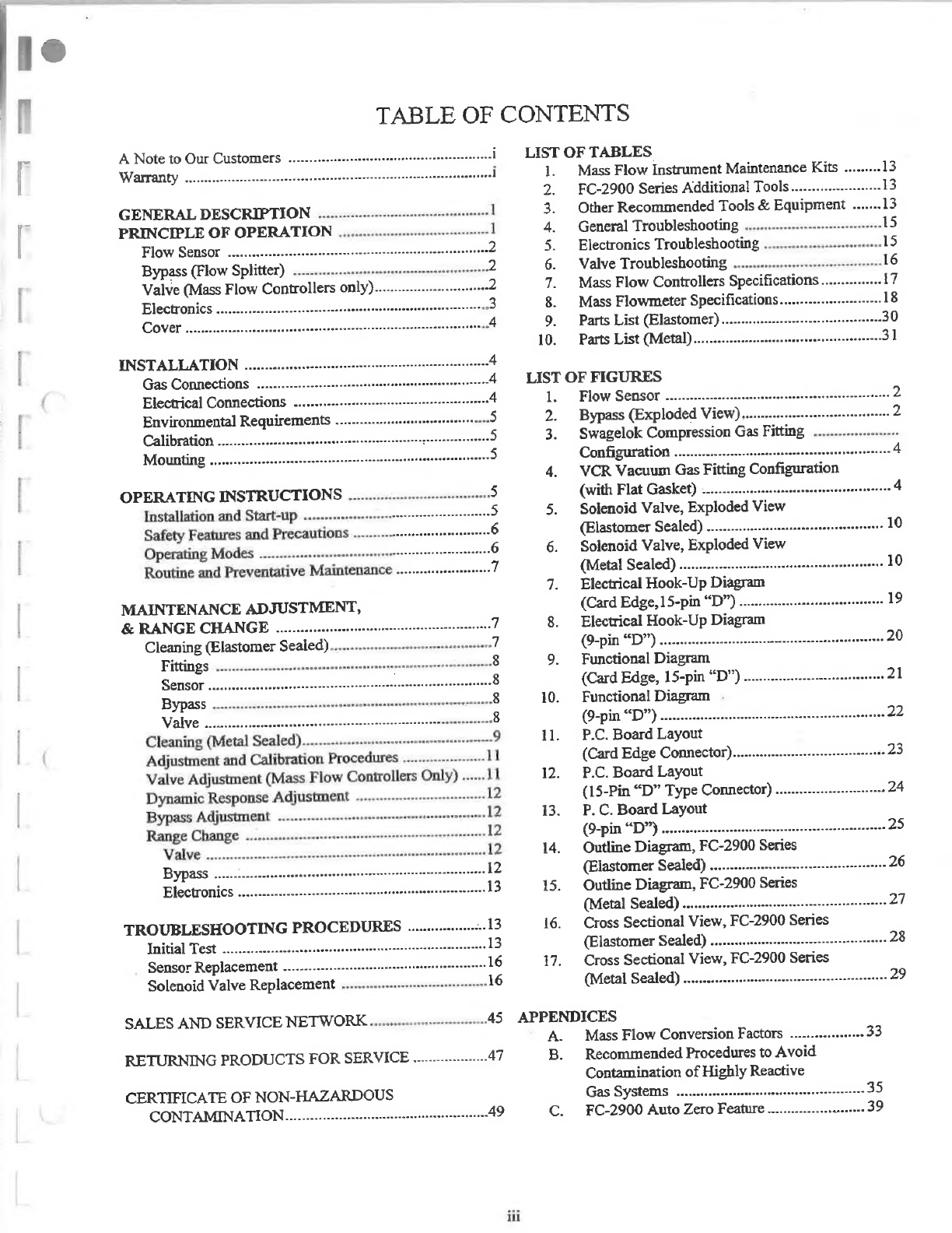
TABLE
ОЕ
CONTENTS
A
Note
to
Our
Customers
.........
а-а...
LIST
OF
TABLES
Warranty
4а
tnnt
nne
enne
1.
Mass
Flow
Instrument
Maintenance
Kits
.........
13
2.
ЕС-2900
Series
Additional
Tools
....................-.
13
GENERAL
DESCRIPTION
............-----.еїєєнөөөөөөөөсєө
3.
Other
Recommended
Tools
&
Equipment
.......
13
PRINCIPLE
OF
OPERATION
4.
General
Troubleshooting
.................................-
Flow
Sensor
................-
ааа.
5.
Electronics
Troubleshooting
.............................
Bypass
(Flow
Splitter)
.......................
6.
Valve
Troubleshooting
.................
n
Valve
(Mass
Flow
Controllers
only).............................
2
7.
Mass
Flow
Controllers
Specifications
Electronics
........................
ennt nnne
nnne ennt
3
8.
Mass
Flowmeter
Specifications.........................
Cover
ДИН
4
9.
Parts
List
(Еізсіютег)...........4.аа
een
10.
Parts
List
(Metal).............................................-
INSTALLATION
......2ә..2............г.м...а.1..2.41!
Gas
Connections
55
Electrical
Connections
.............
eene
4
1.
Flow
Sensor
Дам.
2
Environmental
Requirements
...........ам.4
4
лə
|4...
5
2.
Bypass
(Exploded
View)...
2
Calibration
459
3.
Swagelok
Compression
Gas
Fitting
.....................
Mounting
....42мам12.
М-ы
Configuration
..........
4.4
112...
4
4.
VCR
Vacuum
Gas
Fitting
Configuration
OPERATING
INSTRUCTIONS
...............---.өө
5
(with
Flat
Gasket)
............
eren
4
Installation
and
Start-up
..............-—
5.
Solenoid
Valve,
Exploded
View
Safety
Features
and
Precautions
(Elastomer
Sealed)
......................................
ние
10
Operating
Modes
...............
ener
6.
Solenoid
Valve,
Exploded
View
Routine
and
Preventative
Maintenance
........................
7
(Metal
Sealed)
................
eerte
10
7.
Electrical
Hook-Up
Diagram
MAINTENANCE
ADJUSTMENT,
(Card
Edge,
15-pin
*D")
...................
sse
19
&
RANGE
CHANGE
.........
1
ente
entem
$.
Electrical
Hook-Up
Diagram
Cleaning
(Elastomer
Sealed)
(9-pin
D”)
мама.
ааа
а
аа
ы
20
Fittings
............
n
9.
Functional
Diagram
Sensor
eniin
(Card
Edge,
15-pin
^D")
..............——
21
Bypass
....................
nn
10.
Functional
Diagram
MET
(9-pin
D”)
ЛД
Ды
22
Cleaning
(Metal
Sealed)
11.
Р.С.
Board
Layout
Adjustment
and
Calibration
Procedures
.....................
11
(Сага
Edge
Connector)..............—.—..
1.44.аа
а
а
23
Valve
Adjustment
(Mass
Flow
Controllers
Only)
......
1
12.
P.C.
Board
Layout
Dynamic
Response
Adjustment
....................-.....-....
12
(15-Pin
“D”
Type
Connector)
.............----.--------
24
Bypass
Adjustment
.............
ene
12
13.
P.C.
Board
Layout
Range
Change
............
nennen
12
(9-ріп
“Ю”)
......
eese
tern
teen
25
Valve
3
55
....12
14.
Outline
Diagram,
FC-2900
Series
Bypass
(Elastomer
Sealed)
.................———
A
26
Electronics
15.
Outline
Diagram,
FC-2900
Series
(Metal
Sealed)
.................
eene
27
TROUBLESHOOTING
PROCEDURES
16.
Cross
Sectional
View,
FC-2900
Series
Initial
Тез...
а...
(Elastomer
Sealed)
..............—
A
28
Sensor
Replacement
..................
ЯГ
17.
Cross
Sectional
View,
FC-2900
Series
Solenoid
Valve
Replacement
...............—..
1
421
2Д
2
(Metal
Sealed)
................—
eee
29
SALES
AND
SERVICE
МЕТУУОК..............--өө
45
APPENDICES
A.
Mass
Flow
Conversion
Factors
..................
33
RETURNING
PRODUCTS
FOR
SERVICE
..................
47
B.
Recommended
Procedures
to
Avoid
CERTIFICATE
OF
NON-HAZARDOUS
СОМТАМПШЧАТТОМ................---««є«.енөөөөчлгүөє
49
ili
Contamination
of
Highly
Reactive
Gas
Systems
C.
FC-2900
Auto
Zero
Ееайиге.........................
39

This
page
was
intentionally
left
blank.

"
Wan
Genera
GENERAL
DESCRIPTION
Tylan
General
Model
FC-2900
series
Flow
Controllers
accurately
and
reliably
measure
and
control
the
mass
flow
rate
of
gases.
They
have
been
specifically
designed
to
allow
operation
on
any
gas
having
a
known
molar
specific
heat
(pCp).
The
FC-2900
series
has
a
user-adjustable
range
from
10
sccm
to
30
sim
full-scale
flow
rate.
This
is
accomplished
in
the
flowmeter
section
by
replacing
the
bypass.
In
the
controller
section,
many
changes
in
flow
range
can
be
accomplished
by
an
external
adjustment
of
the
control
valve
alone.
Very
large
range
changes
may
involve
resizing
of
the
valve
orifice.
The
instrument
operates
on
+15
VDC
power,
provides
a
0
to
5.0
VDC
indicated
output
signal
linearly
proportional
to
the
flow
rate,
is
RFI
protected
and
is
both
mechanically
and
electrically
interchangeable
with
most
Tylan
General
mass
flow
controllers.
The
FC-2901/FC-2911
is
equipped
with
a
15-pin
“D”
connector
and
the
FC-2902/FC-2912
is
equipped
with
a
9-pin
“D”
connector.
Either
can
have
0-5
VDC
or
4-20mA
input/output
signals.
For
simplicity,
references
in
this
manual
are
to
a
card
edge
style
P.C.
Board,
+15
VDC
power
source
and
0-5
VDC
input/output
signals.
The
FC-2900B/2910B
operates
from
a
+12
VDC
battery
source.
Other
inherent
design
features
include:
е
Balanced
Power
Load
e
Enhanced
stability
of
both
zero
and
span
e
Auto
Zero
Function
(except
FC-2900B/2910B
and
flowmeters)
e
Metal
seals
with
ultra-high
leak
integrity
of
1
x
10-10
atm-cc/sec.
He
(FC-2900M/2901M/2902M/3900M/3901M/3902M)
Fast
response
with
minimal
overshoot
Battery
Powered
(FC-2900B/2910B)
Normally
closed
or
normaily
open
solenoid
valve
with
both
mechanical
and
electrical
“purge”
capability.
The
FC-2900
series
of
mass
flow
instruments
include:
Mass
Flow
Controllers
FC-2900(O)*
10
sccm
to
10
slm
with
card
edge
connector
FC-2901(0)*
10
sccm
to
10
slm
with
15-pin
“D”
connector
FC-2902(O)*
10
sccm
to
10
slm
with
9-pin
"D"
connector
FC-2910(O)*
100
sccm
to
30
slm
with
card
edge
connector
ЕС-2911(0)*
100
sccm
to
30
sim
with
15-pin
“р”
Connector
100
sccm
to
30
slm
with
9-pin
^D"
connector
FC-2900B(O)*
10
sccm
to
10
slm,
Battery
Powered
FC-2912(O)*
*“Q”
designates
normally
open
valve
option.
FC-2910B(O)*
100
sccm
to
30
slm,
Battery
Powered
FC-2900M(O)*
(EP)**10
sccm
to
30
slm
with
Metal
Seals
and
card
edge
connector
FC-2901M(O)*
(EP)**10
sccm
to
30
sim
with
Metal
Seals
and
15-pin
“D”
connector
коор
(EP)**10
sccm
to
30
sim
with
Metal
Seals
and
9-pin
“D”
connector.
Mass
Flowmeters
FM-3900
10
sccm
to
10
slm
with
card
edge
connector
FM-3901
10
sccm
to
10
sim
with
15-pin
“D”
connector
FM-3902
10
sccm
to
10
slm
with
9-pin
“D”
connector
FM-3910
100
sccm
to
30
sim
with
card
edge
connector
FM-3911
100
sccm
to
30
slm
with
15-pin
"D^
connector
FM-3912
100
sccm
to
30
slm
with
9-pin
“D”
connector
FM-3900M(EP)**
10
sccm
to
30
slm
with
Metal
Seals
and
card
edge
connector
10
sccm
to
30
slm
with
Metal
Seals
and
15-pin
“D”
connector
10
sccm
to
30
slm
with
Metal
Seals
and
9-pin
“D”
connector.
FM-3901M(EP)**
FM-3902M(EP)**
4-20
mA
input/output
signals
(available
with
instruments
that
have
a
*D"
connector).
“J”
option
NOTE:
This
manual
describes
the
operation
and
adjustment
procedures
for
flow
controllers.
All
sections
pertaining
to
the
flowmetering
portion
of
the
controller
also
pertain
to
flowmeters,
while
sections
pertaining
to
the
valve
do
not.
It
should
also
be
noted
that
the
autozero
function
is
not
available
on
any
of
the
flowmeter
models.
`
PRINCIPLE
OF
OPERATION
The
flow
controller
is
a
self-contained,
closed-loop
control
system
which
measures
the
mass
rate
of
gaseous
flow
through
the
instrument,
compares
this
with
an
externally
commanded
flow
rate,
and
adjusts
the
valve
to
control
the
flow
to
the
commanded
level.
The
flow
controller
consists
of
four
basic
elements
which
accomplish
this
function.
°
The
flow
sensor
°
Тһе
bypass,
ог
flow-splitter,
which
determines
the
full-
scale
flow
range
of
the
measuring
section
The
control
valve
The
electronics
which
condition
the
flow
signal
and
drive
the
control
valve.
**“EP”
designates
Electro-polished
option.
Wan
General
Flow
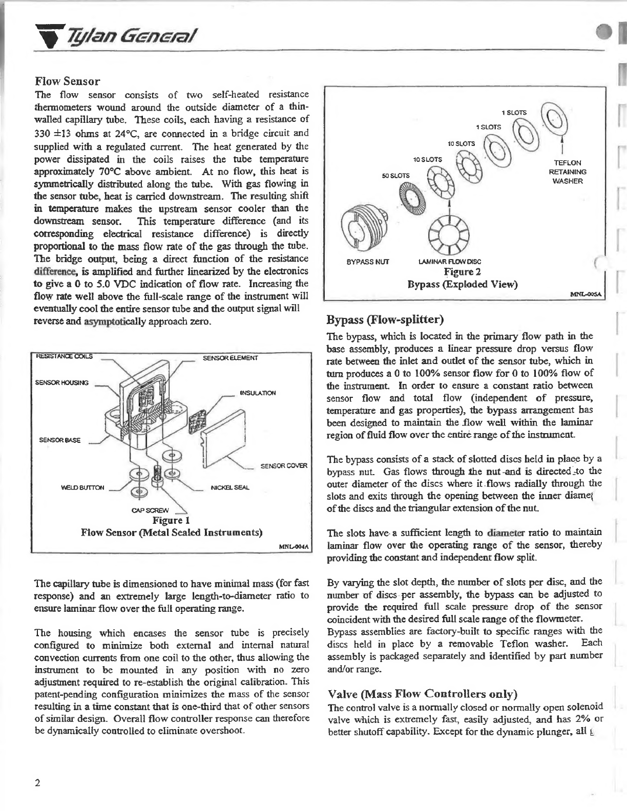
Sensor
The
flow
sensor
consists
of
two
self-heated
resistance
thermometers
wound
around
the
outside
diameter
of
a
thin-
walled
capillary
tube.
These
coils,
each
having
a
resistance
of
330
+13
ohms
at
24°C,
are
connected
in
a
bridge
circuit
and
supplied
with
a
regulated
current.
The
heat
generated
by
the
power
dissipated
in
the
coils
raises
the
tube
temperature
approximately
70°C
above
ambient.
At
no
flow,
this
heat
is
symmetrically
distributed
along
the
tube.
With
gas
flowing
in
the
sensor
tube,
heat
is
carried
downstream.
The
resulting
shift
in
temperature
makes
the
upstream
sensor
cooler
than
the
downstream
sensor.
This
temperature
difference
(and
its
corresponding
electrical
resistance
difference)
is
directly
proportional
to
the
mass
flow
rate
of
the gas
through
the
tube.
The
bridge
output,
being
a
direct
function
of
the
resistance
difference,
is
amplified
and
further
linearized
by
the
electronics
to
give
a
0
to
5.0
VDC
indication
of
flow
rate.
Increasing
the
flow
rate
well
above
the
full-scale
range
of
the
instrument
will
eventually
cool
the
entire
sensor
tube
and
the
output
signal
will
reverse
and
asymptotically
approach
zero.
INSULATION
Р
|
.
SENSOR
COVER
Figure
1
Flow
Sensor
(Metal
Sealed
Instruments)
The
capillary
tube
is
dimensioned
to
have
minimal
mass
(for
fast
response)
and
an
extremely
large
length-to-diameter
ratio
to
ensure
laminar
flow
over
the
full
operating
range.
The
housing
which
encases
the
sensor
tube
is
precisely
configured
to
minimize
both
extemal
and
internal
natural
convection
currents
from
one
coil
to
the
other,
thus
allowing
the
instrument
to
be
mounted
in
any
position
with
no
zero
adjustment
required
to
re-establish
the
original
calibration.
This
patent-pending
configuration
minimizes
the
mass
of
the
sensor
resulting
in
a
time
constant
that
is
one-third
that
of
other
sensors
of
similar
design.
Overall
flow
controller
response
can
therefore
be
dynamically
controlled
to
eliminate
overshoot.
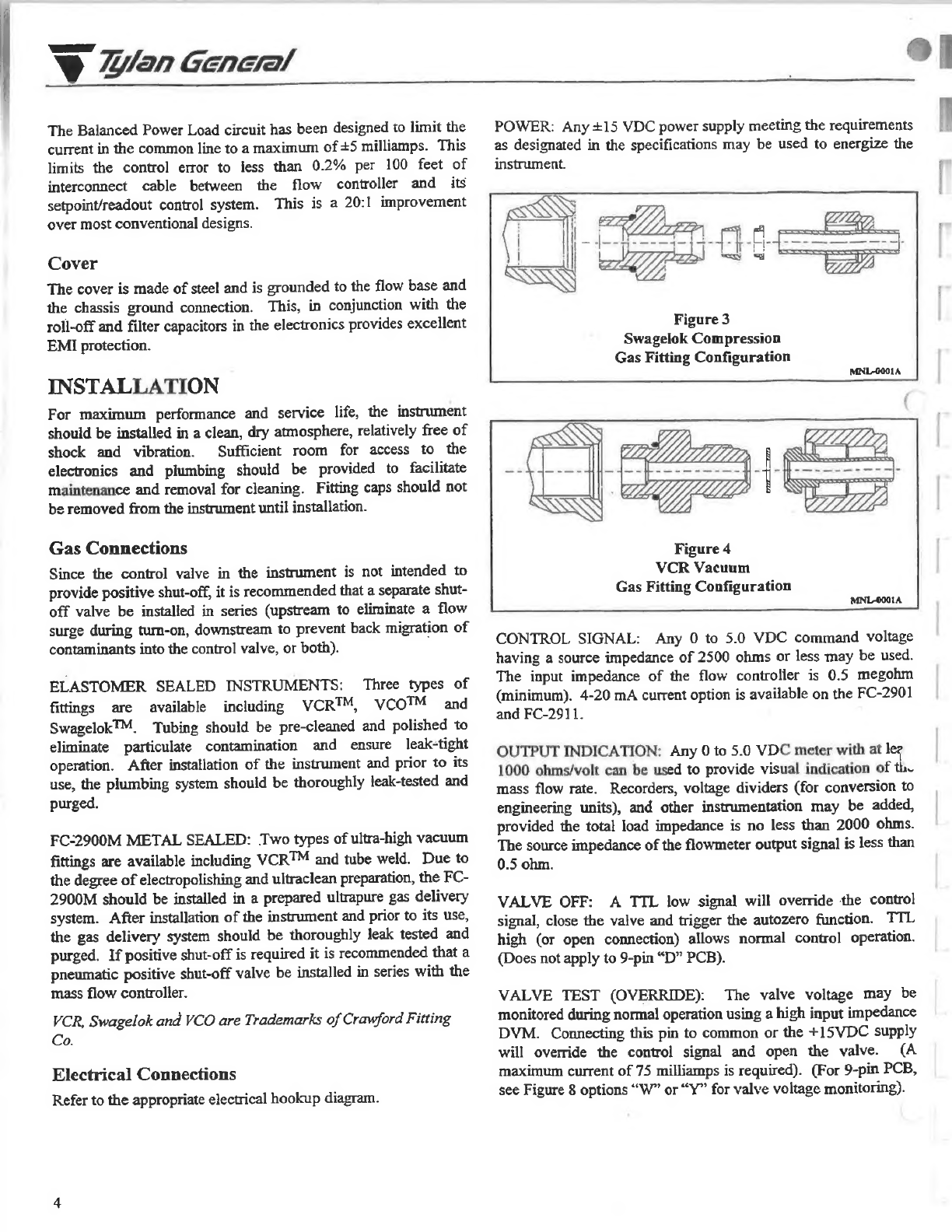
1SLOTS
10
SLOTS
10
SLOTS
WASHER
BYPASS
NUT
LAMINAR
FLOW
DISC
Figure
2
Bypass
(Exploded
View)
Bypass
(Flow-splitter)
The
bypass,
which
is
located
in
the
primary
flow
path
in
the
base
assembly,
produces
a
linear
pressure
drop
versus
flow
rate
between
the
inlet
and
outlet
of
the
sensor
tube,
which
in
turn
produces
a
0
to
100%
sensor
flow
for
0
to
100%
flow
of
the
instrument.
In
order
to
ensure
a
constant
ratio
between
sensor
flow
and
total
flow
(independent
of
pressure,
temperature
and
gas
properties),
the
bypass
arrangement
has
been
designed
to
maintain
the
flow
well
within
the
laminar
region
of
fluid
flow
over
the
entiré
range
of
the
instrument.
The
bypass
consists
of
a
stack
of
slotted
discs
held
in
place
by
a
bypass
nut.
Gas
flows
through
the
nut-and
is
directed
40
the
outer
diameter
of
the
discs
where
it.flows
radially
through
the
slots
and
exits
through
the
opening
between
the
inner
diame;
of
the
discs
and
the
triangular
extension
of
the
nut.
The
slots
have.
а
sufficient
length
to
diameter
ratio
to
maintain
laminar
flow
over
the
operating
range
of
the
sensor,
thereby
providing
the
constant
and
independent
flow
split.
By
varying
the
slot
depth,
the
number
of
slots
per
disc,
and
the
number
of
discs
per
assembly,
the
bypass
can
be
adjusted
to
provide
the
required
full
scale
pressure
drop
of
the
sensor
coincident
with
the
desired
full
scale
range
of
the
flowmeter.
Bypass
assemblies
are
factory-built
to
specific
ranges
with
the
discs
held
in
place
by
a
removable
Teflon
washer.
Each
assembly
is
packaged
separately
and
identified
by
part
number
and/or
range.
Valve
(Mass
Flow
Controllers
only)
The
control
valve
is
a
normally
closed
or
normally
open
solenoid
valve
which
is
extremely
fast,
easily
adjusted,
and
has
2%
or
better
shutoff
capability.
Except
for
the
dynamic
plunger,
all
£

19
W
Wan
General
|
wetted
metal
surfaces
are
of
type
316L
stainless
steel.
The
plunger
is
constructed
of
type
446
stainless
steel.
The
range
of
the
valve
is
determined
by
the
size
of
the
control
orifice,
which
is
screwed
into
the
controller
base.
These
precision
valve
seats
are
type
316L
stainless
steel
and
provide
excellent
control
resolution
by
engagement
with
the
Teflon
face
of
the
valve
poppet.
The
valve
seats
are
easily
replaceable
for
cleaning
and
instrument
range
changing.
The
valve
seat
is
designed
to
provide
a
relatively
constant
control
range
(stroke)
over
the
entire
flow
range.
Different
ranges
within
the
full
range
of
a
particular
valve
seat
are
accommodated
by
the
amount
of
voltage
applied
to
the
valve.
This
arrangement
provides
consistent
dynamic
response
and
static
stability
with
only
a
minimal
need
for
electronic“
tuning.”
An
adjustment
on
top
of
the
valve
is
provided
to
allow
for
setting
the
relative
position
between
the
valve
poppet
and
valve
seat
following
re-assembly
after
cleaning
or
seat
replacement
(see
Adjustment
Procedures).
This
adjusting
nut
may
also
be
used
to
mechanically
open
the
valve
for
purging
purposes
in
the
event
of
a
power
failure
or
an
instrument
malfunction,
which
may
necessitate
removing
the
instrument
from
the
gas
system.
Electronics
The
electronics
consist
of
a
circuit
board
with
a
hybrid
autozero
circuit
soldered
in
place.
Surface
mount
technology
is
utilized
in
the
FC-2900
series.
Referring
to
the
Electrical
Hook-Up
Diagram,
JO
is
a
card
edge,
9-pin
“D”
or
15-pin
“D”
connector
that
interfaces
with
the
external
control
system.
A
positive
5
volt
regulator
supplies
power
to
the
Auto-Zero
circuit
and
also
provides
the
reference
voltage
required
for
the
“Valve
OFF”
function.
The
negative
5
volt
regulator
provides
the
reference
for
the
sensor
bridge
constant
current
source
and
the
linearization
circuit.
The
Current
Sonrce
delivers
a
constant
12.7
milliamps
to
the
sensor
bridge
which
“floats”
between
the
plus
and
minus
supplies.
This
arrangement
gives
extremely
high
common-mode
rejection
and
allows
insensitive
operation
over
a
wide
range
of
supply
voltage
levels.
The
Sensor
Bridge
circuit
contains
the
zero
and
span
temperature
compensation
networks.
The
Flowmeter
Amplifier
circuit
amplifies
the
sensor
output
signal,
the
gain
of
which
is
adjusted
by
RP2
at
50%
full
scale
flow
rate.
This
circuit
also
incorporates
a
speed-up
filter
which
provides
for
matching
the
sensor
response
to
the
actual
flow
rate
response
during
a
transient
flow
condition.
The
AC
gain
versus
frequency
is
adjusted
by
RP3.
This
adjustment
is
fine-tuned
by
observing
the
output
waveform
in
response
to
step
changes
in
setpoint
and
actual
flow
rate.
The
Linearity
circuit
provides
a
variable
gain
versus
input
voltage
allowing
correction
for
any
non-linearity
of
the
sensor
output
signal.
The
adjustment
is
made
by
RP4
at
100%
full-
scale
flow
rate.
The
Auto-Zero
circuit
provides
periodic
correction
of
zero
offset
due
to
long
term
sensor
drift,
temperature
and
pressure
variations,
or
other
environmental
causes.
This
feature
ensures
long
term
calibration
accuracy
and
eliminates
the
need
for
periodic
manual
zero
adjustment.
The
range
of
correction
is
limited
to
+2.5%
of
full
scale
to
prevent
erroneous
correction
of
an
undetectable
leak
or
defective
sensor.
The
auto-zero
function
is
activated
either
by
commanding
<1%
of
full
scale
flow
rate
which
automatically
closes
the
control
valve
or
connecting
pin
L
to
common.
After
80
to
100
seconds,
the
output
signal
is
compared
with
(and
driven
to)
zero
within
2.5
seconds.
This
correction
is
maintained
until
the
next
update.
The
current
or
latest
correction
can
be
permanently
stored
in
memory
by
an
external
command
such
that
in
the
event
of
power
loss,
the
output
will
return
to
zero
when
power
is
re-applied.
The
auto-zero
functions
may
be
inhibited
either
externally
by
connecting
pin
J
to
common
(See
Electrical
Hook-Up
Diagram)
or
internally,
by
removing
jumper
JP2.
See
Appendix
C
for
more
information.
The
Valve
Control
circuit
compares
the
flowmeter
output
signal
with
the
command
voltage
(setpoint)
and
varies
the
voltage
to
the
valve
to
throttle
the
flow
to
the
commanded
level
via
closed
loop
control.
The
ramp
circuit
limits
the
rate
of
change
of
the
setpoint
allowing
the
sensor
output
to
“Кеер-ир”,
thus
minimizing
overshoot
during
step
changes
in
commanded
flow
rate.
If
a
slower
response
is
desired,
jumper
JP1
can
be
removed
to
give
a
10-15%
per
second
rate
of
change
to
the
desired
flow
rate.
?
While
the
integral
and
derivative
functions
of
the
PID
control
circuit
are
relatively
fixed,
the
proportional
band
(gain)
of
the
circuit
is
adjusted
by
the
ratio
of
R52
to
R50.
The
values
of
these
resistors
are
selected
during
dynamic
response
testing
to
optimize
the
transient
response
of
the
control
loop,
and
vary
depending
on
the
range,
gas,
and
intended
operating
conditions
of
the
instrument.
The
control
logic
can
be
overridden
externally
to
either
open
or
close
the
valve
in
accordance
with
specific
process
requirements.
(See
Electrical
Hook-Up
Diagram).
NOTE:
While
connecting
pin
D
to
common
will
partially
open
the
normally
closed
valve
and
partially
close
the
normally
open
valve,
connecting
pin
D
to
+15
VDC
will
drive
the
normally
closed
valve
to
the
full
“purge”
position
and
close
the
normally
open
valve.
$
Wan
General
The
Balanced
Power
Load
circuit
has
been
designed
to
limit
the
current
in
the
common
line
to
a
maximum
of
+5
milliamps.
This
limits
the
control
error
to
less
than
0.296
per
100
feet
of
interconnect
cable
between
the
flow
controller
and
its
setpoint/readout
control
system.
This
is
a
20:1
improvement
over
most
conventional
designs.
Cover
The
cover
is
made
of
steel
and
is
grounded
to
the
flow
base
and
the
chassis
ground
connection.
This,
in
conjunction
with
the
roll-off
and
filter
capacitors
in
the
electronics
provides
excellent
EMI
protection.
INSTALLATION
For
maximum
performance
and
service
life,
the
instrument
should
be
installed
in
a
clean,
dry
atmosphere,
relatively
free
of
shock
and
vibration.
Sufficient
room
for
access
to
the
electronics
and
plumbing
should
be
provided
to
facilitate
maintenance
and
removal
for
cleaning.
Fitting
caps
should
not
be
removed
from
the
instrument
until
installation.
Gas
Connections
Since
the
control
valve
in
the
instrument
is
not
intended
to
provide
positive
shut-off,
it
is
recommended
that
a
separate
shut-
off
valve
be
installed
in
series
(upstream
to
eliminate
a
flow
surge
during
turn-on,
downstream
to
prevent
back
migration
of
contaminants
into
the
control
valve,
or
both).
ELASTOMER
SEALED
INSTRUMENTS:
Three
types
of
fittings
are
available
including
ҮСЕТМ,
VCOIM
and
Swagelok™,
Tubing
should
be
pre-cleaned
and
polished
to
eliminate
particulate
contamination
and
ensure
leak-tight
operation.
After
installation
of
the
instrument
and
prior
to
its
use,
the
plumbing
system
should
be
thoroughly
leak-tested
and
purged.
FC-2900M
METAL
SEALED:
Two
types
of
ultra-high
vacuum
fittings
are
available
including
VCR™
and
tube
weld.
Due
to
the
degree
of
electropolishing
and
ultraclean
preparation,
the
FC-
2900M
should
be
installed
in
a
prepared
ultrapure
gas
delivery
system.
After
installation
of
the
instrument
and
prior
to
its
use,
the
gas
delivery
system
should
be
thoroughly
leak
tested
and
purged.
If
positive
shut-off
is
required
it
is
recommended
that
a
pneumatic
positive
shut-off
valve
be
installed
in
series
with
the
mass
flow
controller.
VCR,
Swagelok
and
VCO
are
Trademarks
of
Crawford
Fitting
Co.
Electrical
Connections
Refer
to
the
appropriate
electrical
hookup
diagram.
POWER:
Any
+15
VDC
power
supply
meeting
the
requirements
as
designated
in
the
specifications
may
be
used
to
energize
the
instrument.
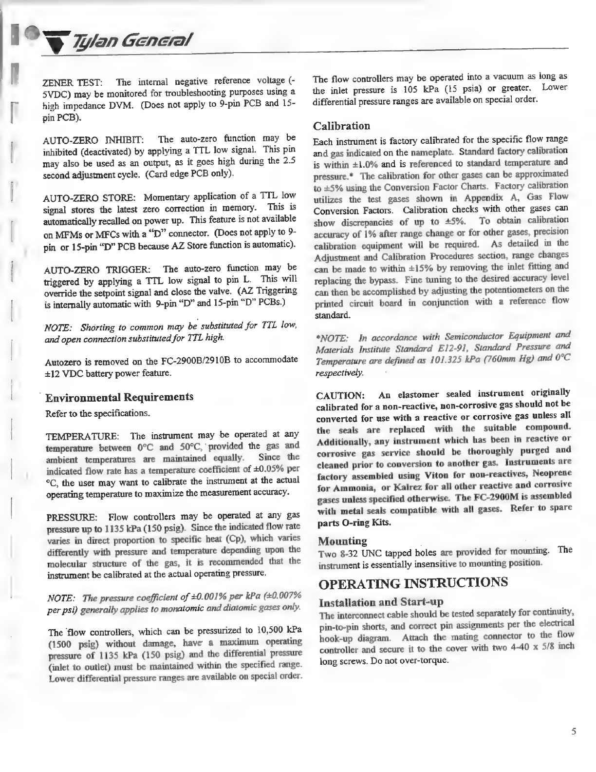
==
Figure
3
Swagelok
Compression
Gas
Fitting
Configuration
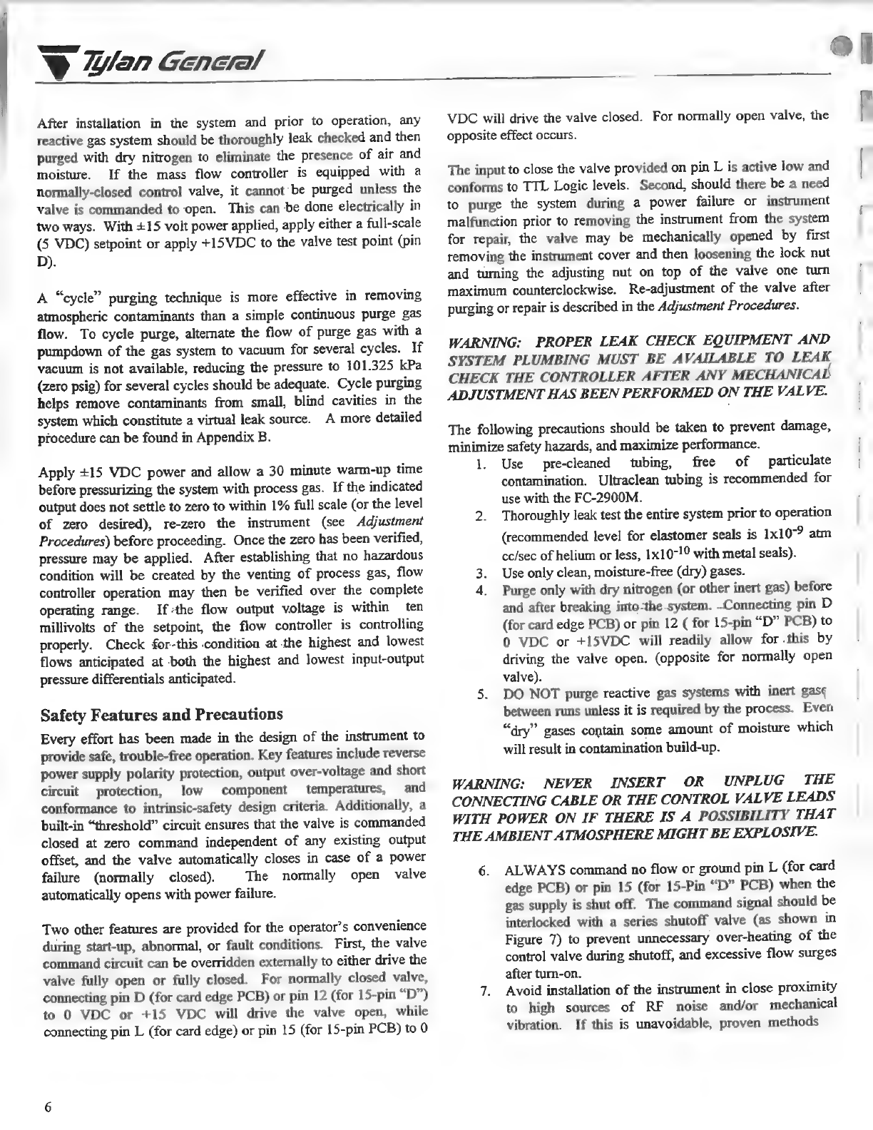
Figure
4
VCR
Vacuum
Gas
Fitting
Configuration
CONTROL
SIGNAL:
Any
0
to
5.0
VDC
command
voltage
having
a
source
impedance
of
2500
ohms
or
less
may
be
used.
The
input
impedance
of
the
flow
controller
is
0.5
megohm
(minimum).
4-20
mA
current
option
is
available
on
the
FC-2901
and
FC-2911.
OUTPUT
INDICATION:
Any
0
to
5.0
VDC
meter
with
at
lez
1000
ohms/volt
can
be
used
to
provide
visual
indication
of
th~
mass
flow
rate.
Recorders,
voltage
dividers
(for
conversion
to
engineering
units),
and
other
instrumentation
may
be
added,
provided
the
total
load
impedance
is
no
less
than
2000
ohms.
The
source
impedance
of
the
flowmeter
output
signal
is
less
than
0.5
ohm.
VALVE
OFF:
А
TTL
low
signal
will
override
the
control
signal,
close
the
valve
and
trigger
the
autozero
function.
TTL
high
(or
open
connection)
allows
normal
control
operation.
(Does
not
apply
to
9-pin
“D”
РСВ).
VALVE
TEST
(OVERRIDE):
The
valve
voltage
may
be
monitored
during
normal
operation
using
a
high
input
impedance
DVM.
Connecting
this
pin
to
common
or
the
+15VDC
supply
will
override
the
control
signal
and
open
the
valve.
(A
maximum
current
of 75
milliamps
is
required).
(For
9-pin
PCB,
see
Figure
8
options
“W”
or
“Y”
for
valve voltage
monitoring).
19
$
Zan
General
|
ZENER
TEST:
The
internal
negative
reference
voltage
(-
5ҮРС)
may
be
monitored
for
troubleshooting
purposes
using
a
high
impedance
DVM.
(Does
not
apply
to
9-pin
PCB
and
15-
pin
PCB).
AUTO-ZERO
INHIBIT:
The
auto-zero
function
may
be
inhibited
(deactivated)
by
applying
a
TTL
low
signal.
This
pin
may
also
be
used
as
an
output,
as
it
goes
high
during
the
2.5
second
adjustment
cycle.
(Card
edge
PCB
only).
AUTO-ZERO
STORE:
Momentary
application
of
a
TTL
low
signal
stores
the
latest
zero
correction
in
memory.
This
is
automatically
recalled
on
power
up.
This
feature
is
not
available
on
MFMs
or
MFCs
with
a
“D”
connector.
(Does
not
apply
to
9-
pin
or
15-pin
“D”
PCB
because
AZ
Store
function
is
automatic).
AUTO-ZERO
TRIGGER:
The
auto-zero
function
may
be
triggered
by
applying
a
TTL
low
signal
to
pin
L.
This
will
override
the
setpoint
signal
and
close
the
valve.
(AZ
Triggering
is
internally
automatic
with
9-pin
“D”
and
15-pin
“D”
PCBs.)
NOTE:
Shorting
to
common
may
be
substituted
for
TTL
low,
and
open
connection
substituted
for
TTL
high.
Autozero
is
removed
on
the
FC-2900B/2910B
to
accommodate
+12
VDC
battery
power
feature.
`
Environmental
Requirements
Refer
to
the
specifications.
TEMPERATURE:
The
instrument
may
be
operated
at
any
temperature
between
09С
and
50°C,
provided
the
gas
and
ambient
temperatures
are
maintained
equally.
Since
the
indicated
flow
rate
has
a
temperature
coefficient
of
+0.05%
рег
°C,
the
user
may
want
to
calibrate
the
instrument
at
the
actual
operating
temperature
to
maximize
the
measurement
accuracy.
PRESSURE:
Flow
controllers
may
be
operated
at
any
gas
pressure
up
to
1135
kPa
(150
psig).
Since
the
indicated
flow
rate
varies
in
direct
proportion
to
specific
heat
(Cp),
which
varies
differently
with
pressure
and
temperature
depending
upon
the
molecular
structure
of
the
gas,
it
is
recommended
that
the
instrument
be
calibrated
at
the
actual
operating
pressure.
NOTE:
The
pressure
coefficient
of
+0.001%
per
kPa
(+0.
007%
per
psi)
generally
applies
to
monatomic
and
diatomic
gases
only.
The
flow
controllers,
which
can
be
pressurized
to
10,500
kPa
(1500
psig)
without
damage,
have
a
maximum
operating
pressure
of
1135
kPa
(150
psig)
and
the
differential
pressure
(inlet
to
outlet)
must
be
maintained
within
the
specified
range.
Lower
differential
pressure
ranges
are
available
on
special
order.
The
flow
controllers
may
be
operated
into
a
vacuum
as
long
as
the
inlet
pressure
is
105
kPa
(15
psia)
or
greater.
Lower
differential
pressure
ranges
are
available
on
special
order.
Calibration
Each
instrument
is
factory
calibrated
for
the
specific
flow
range
and
gas
indicated
on
the
nameplate.
Standard
factory
calibration
is
within
+1.0%
and
is
referenced
to
standard
temperature
and
pressure.*
The
calibration
for
other
gases
can
be
approximated
to
+5%
using
the
Conversion
Factor
Charts.
Factory
calibration
utilizes
the
test
gases
shown
in
Appendix
A,
Gas
Flow
Conversion
Factors.
Calibration
checks
with
other
gases
can
show
discrepancies
of
up
to
+5%.
To
obtain
calibration
accuracy
of
1%
after
range
change
or
for
other
gases,
precision
calibration
equipment
will
be
required.
As
detailed
in
the
Adjustment
and
Calibration
Procedures
section,
range
changes
can
be
made
to
within
+15%
by
removing
the
inlet
fitting
and
replacing
the
bypass.
Fine
tuning
to
the
desired
accuracy
level
can
then
be
accomplished
by
adjusting
the
potentiometers
on
the
printed
circuit
board
in
conjunction
with
a
reference
flow
standard.
*NOTE:
In
accordance
with
Semiconductor
Equipment
and
Materials
Institute
Standard
E12-91,
Standard
Pressure
and
Temperature
are
defined
as
101.325
kPa
(760mm
Hg)
and
0°C
respectively.
CAUTION:
An
elastomer
sealed
instrument
originally
calibrated
for
a
non-reactive,
non-corrosive
gas
should
not
be
converted
for
use
with
a
reactive
or
corrosive
gas
unless
all
the
seals
are
replaced
with
the
suitable
compound.
Additionally,
any
instrument
which
has
been
in
reactive
or
corrosive
gas
service
should
be
thoroughly
purged
and
cleaned
prior
to
conversion
to
another
gas.
Instruments
are
factory
assembled
using
Viton
for
non-reactives,
Neoprene
for
Ammonia,
or
Kalrez
for
all
other
reactive
and
corrosive
gases
unless
specified
otherwise.
The
FC-2900M
is
assembled
with
metal
seals
compatible
with
all
gases.
Refer
to
spare
parts
O-ring
Kits.
Mounting
|
Two
8-32
UNC
tapped
holes
are
provided
for
mounting.
The
instrument
is
essentially
insensitive
to
mounting
position.
OPERATING
INSTRUCTIONS
Installation
and
Start-up
The
interconnect
cable
should
be
tested
separately
for
continuity,
pin-to-pin
shorts,
and
correct
pin
assignments
per
the
electrical
hook-up
diagram.
Attach
the
mating
connector
to
the
flow
controller
and
secure
it
to
the
cover
with
two
4-40
x
5/8
inch
long
screws.
Do
not
over-torque.
$
Wan
General
After
installation
in
the
system
and
prior
to
operation,
any
reactive
gas
system
should
be
thoroughly
leak
checked
and
then
purged
with
dry
nitrogen
to
eliminate
the
presence
of
air
and
moisture.
If
the
mass
flow
controller
is
equipped
with
a
normally-closed
control
valve,
it
cannot
be
purged
unless
the
valve
is
commanded
to
open.
This
can
be
done
electrically
in
two
ways.
With
+15
volt
power
applied,
apply
either
a
full-scale
(5
VDC)
setpoint
or
apply
+15VDC
to
the
valve
test
point
(pin
D).
A
"cycle"
purging
technique
is
more
effective
in
removing
atmospheric
contaminants
than
a
simple
continuous
purge
gas
flow.
To
cycle
purge,
alternate
the
flow
of
purge
gas
with
a
pumpdown
of
the
gas
system
to
vacuum
for
several
cycles.
If
vacuum
is
not
available,
reducing
the
pressure
to
101.325
kPa
(zero
psig)
for
several
cycles
should
be
adequate.
Cycle
purging
helps
remove
contaminants
from
small,
blind
cavities
in
the
system
which
constitute
a
virtual
leak
source.
A
more
detailed
procedure
can
be
found
in
Appendix
B.
Apply
+15
VDC
power
and
allow
a
30
minute
warm-up
time
before
pressurizing
the
system
with
process
gas.
If
the
indicated
output
does
not
settle
to
zero
to
within
1%
full
scale
(or
the
level
of
zero
desired),
re-zero
the
instrument
(see
Adjustment
Procedures)
before
proceeding.
Once
the
zero
has
been
verified,
pressure
may
be
applied.
After
establishing
that
no
hazardous
condition
will
be
created
by
the
venting
of
process
gas,
flow
controller
operation
may
then
be
verified
over
the
complete
operating
range.
Ifthe
flow
output
voltage
is
within
ten
millivolts
of
the
setpoint,
the
flow
controller
is
controlling
properly.
Check
for-this
condition
at
the
highest
and
lowest
flows
anticipated
at
both
the
highest
and
lowest
input-output
pressure
differentials
anticipated.
Safety
Features
and
Precautions
Every
effort
has
been
made
in
the
design
of
the
instrument
to
provide
safe,
trouble-free
operation.
Key
features
include
reverse
power
supply
polarity
protection,
output
over-voltage
and
short
circuit
protection,
low
component
temperatures,
and
conformance
to
intrinsic-safety
design
criteria.
Additionally,
a
built-in
“threshold”
circuit
ensures
that
the
valve
is
commanded
closed
at
zero
command
independent
of
any
existing
output
offset,
and
the
valve
automatically
closes
in
case
of
a
power
failure
(normally
closed).
The
normally
open
valve
automatically
opens
with
power
failure.
Two
other
features
are
provided
for
the
operator’s
convenience
during
start-up,
abnormal,
or
fault
conditions.
First,
the
valve
command
circuit
can
be
overridden
externally
to
either
drive
the
valve
fully
open
or
fully
closed.
For
normally
closed
valve,
connecting
pin
D
(for
card
edge
PCB)
or
pin
12
(for
15-pin
“D”)
to
0
VDC
or
+15
VDC
will
drive
the
valve
open,
while
connecting
pin
L
(for
card
edge)
or
pin
15
(for
15-pin
PCB)
to
0
VDC
will
drive
the
valve
closed.
For
normally
open
valve,
the
opposite
effect
occurs.
The
input
to
close
the
valve
provided
on
pin
L
is
active
low
and
conforms
to
TTL
Logic
levels.
Second,
should
there
be
a
need
to
purge
the
system
during
a
power
failure
or
instrument
malfunction
prior
to
removing
the
instrument
from
the
system
for
repair,
the
valve
may
be
mechanically
opened
by
first
removing
the
instrument
cover
and
then
loosening
the
lock
nut
and
turning
the
adjusting
nut
on
top
of
the
valve
one
turn
maximum
counterclockwise.
Re-adjustment
of
the
valve
after
purging
or
repair
is
described
in
the
Adjustment
Procedures.
WARNING:
PROPER
LEAK
CHECK
EQUIPMENT
AND
SYSTEM
PLUMBING
MUST
BE
AVAILABLE
TO
LEAK
CHECK
THE
CONTROLLER
AFTER
ANY
MECHANICAL
ADJUSTMENT
HAS
BEEN
PERFORMED
ON
THE
VALVE.
The
following
precautions
should
be
taken
to
prevent
damage,
minimize
safety
hazards,
and
maximize
performance.
1.
Use
pre-cleaned
tubing,
free
of
particulate
contamination.
Ultraclean
tubing
is
recommended
for
use
with
the
FC-2900M.
2.
Thoroughly
leak
test
the
entire
system
prior
to
operation
(recommended
level
for
elastomer
seals
is
1х10-?
atm
cc/sec
of
helium
or
less,
1х10-10
with
metal
seals).
3.
Use
only
clean,
moisture-free
(dry)
gases.
4.
Purge
only
with
dry
nitrogen
(or
other
inert
gas)
before
and
after
breaking
into-the
system.
Connecting
pin
D
(for
card
edge
PCB)
or
pin
12
(
for
15-pin
“D”
PCB)
to
0
VDC
ог
+15VDC
will
readily
allow
for
this
by
driving
the
valve
open.
(opposite
for
normally
open
valve).
5.
DO
NOT
purge
reactive
gas
systems
with
inert
вазе
between
runs
unless
it
is
required
by
the
process.
Even
“dry”
gases
contain
some
amount
of
moisture
which
will
result
in
contamination
build-up.
WARNING:
NEVER
INSERT
OR
UNPLUG
THE
CONNECTING
CABLE
OR
THE
CONTROL
VALVE
LEADS
WITH
POWER
ON
IF
THERE
IS
A
POSSIBILITY
THAT
THE
AMBIENT
ATMOSPHERE
MIGHT
BE
EXPLOSIVE.
6.
ALWAYS
command
no
flow
or
ground
pin
L
(for
card
edge
PCB)
or
pin
15
(for
15-Pin
“D”
PCB)
when
the
gas
supply
is
shut
off.
The
command
signal
should
be
interlocked
with
a
series
shutoff
valve
(as
shown
in
Figure
7)
to
prevent
unnecessary
over-heating
of
the
control
valve
during
shutoff,
and
excessive
flow
surges
after
turn-on.
7.
Avoid
installation
of
the
instrument
in
close
proximity
to
high
sources
of
RF
noise
and/or
mechanical
vibration.
If
this
is
unavoidable,
proven
methods

1o
ПИЛ
General
ү-?
ЭЛЭЭЖ
——-
instrumentation
filtering,
cable
shielding,
and/or
shock
mounting
should
be
utilized.
8.
See
Caution
Note
on
page
5
before
converting
any
elastomer
sealed
instrument
for
operation
on
a
gas
other
than
what
it
was
originally
calibrated
for
or
previously
used
on.
Operating
Modes
In
general,
the
instruments
may
be
operated
at
any
pressure
and
temperature
that
falls
within
the
limits
stated
in
the
specification.
Optimum
performance,
however,
can
be
achieved
and
will
prevail
if
the
operating
pressure
and
temperature
are
pre-
determined
and
controlled
to
a
narrow
range.
Calibrating
and
‘fine
tuning”
the
instruments
at
the
actual
operating
pressure,
temperature
and
flow
rates
can
significantly
improve
the
performance
characteristics.
The
instruments
are
factory
calibrated
at
an
ambient
temperature
of
23°C
(43°C)
and
the
inlet
pressure
set
to
the
midpoint
of
the
operating
pressure
range
and
corrected
to
standard
conditions.
Flow
controllers
are
adjusted
to
pass
full
rated
flow
at
the
minimum
inlet
pressure,
with
101.325
kPa
(0
psig)
outlet
pressure
and
shut
down
to
less
than
2%
of
full
scale
at
the
maximum
inlet
pressure.
Response
time
is
verified
at
both
extremes.
If
the
control
valve
is
normally
closed,
it
is
not
necessary
to
provide
an
external
time-delayed
“soft-start”
signal
provided
the
command
signal
is
maintained
at
zero
during
the
“off”
mode
and
is
then
applied
to
the
instrument
at
the
same
time
(or
after)
pressure
is
applied.
Alternately,
“Valve
Off"
pin
connected
momentarily
to
common
prior
to
applying
gas
pressure
also
prevents
excessive
flow
transients
at
turn-on.
A
slower
ramp
change
may
also
be
selected
for
vacuum
systems
which
have
small
volumes
and
large
flow
rates
or
in
other
applications
where
a
slower
ramped
change
in
flow
rate
is
desirable.
Flow
controllers
may
be
operated
at
inlet
pressures
of
up
to
1135
kPa
(150
psig),
provided
the
differential
pressure
is
maintained
within
the
175
kPa
to
380
kPa
(10
to
40
psig)
range
and
the
outlet
pressure
of
the
flow
controller
is
regulated
to
a
relatively
constant
level.
Flow
controllers
can
withstand
pressure
surges
of
up
to
10,500
kPa
(1500
psig)
without
damage,
but
are
not
designed
to
operate
in
a
controlling
mode
above
1135
kPa
(150
psig)
inlet
pressure.
Routine
and
Preventative
Maintenance
It
is
recommended
that
a
routine
maintenance
schedule
be
established
on
each
instrument
in
order
to
maximize
its
useful
service
life.
This
would
include,
as
a
minimum,
cleaning
and
recalibration.
It
is
recommended
that
calibration
be
done
at
least
once
a
year.
The
optimum
(or
necessary)
service
period
is
dependent
on
usage,
environmental
conditions,
gas
corrosiveness,
etc.,
and
must
be
established
by
the
user
based
upon
historical
experience
in
that
particular
application.
The
recommended
steps
for
routine
and
preventative
maintenance
are
as
follows:
1.
Purge
the
instrument
with
dry
nitrogen
fora
minimum
of
30
minutes
prior
to
removal
from
the
system
(See
Appendix
B
for
detailed
purge
procedure).
2.
Verify
the
calibration
of
the
flow
metering
section
by
comparison
with
a
suitable
reference
standard
or
calibrator.
3.
Operate
the
instrument
in
the
control
mode
over
its
entire
operating
range
(2
to
100%
full
scale)
at
the
minimum
and
maximum
inlet
pressures
of
175
kPa
and
380
kPa
(10
and
40
psig).
Check
response,
stability
and
control
resolution.
4.
Remove
the
inlet
and
outlet
fittings
of
elastomer
sealed
instruments
and
visually
examine
for
signs
of
contamination.
Examine
the
seals
for
any
evidence
of
cracking,
hardening,
swelling
ог
contaminant
accumulation.
Do
not
attempt
to
disassemble
the
FC-
2900M
unless
replacement
seals
are
available.
5.
Based
upon
the
results
of
steps
1
through
4
above,
either
reinstall
in
the
system
(followed
by
a
nitrogen
purge)
or
proceed
to
the
applicable
Cleaning,
Adjustment
and/or
Calibration
Procedure
described
in
this
manual.
MAINTENANCE,
ADJUSTMENT
AND
RANGE
CHANGE
NOTE:
The
following
instructions
and
procedures
are
intended
for
a
laboratory
bench
top
environment.
Proper
equipment
and
precautions
should
be
used
for
any
other
system
or
environment.
Cleaning
(Elastomer
Sealed
Instruments)
Should
the
instrument
show
symptoms
of
internal
flow
path
contamination,
it
should
be
disassembled
and
cleaned.
Elastomer
seals
on
the
fittings,
sensor
and
valve
should
be
examined
for
hardening,
swelling,
inflexibility,
and/or
contamination
accumulation
and
should
be
replaced
if
any
of
these
symptoms
prevail
relative
to
new
and
unused
seals.
The
recommended
sequence
of
solvents
used
for
cleaning
(either
for
flushing
the
assembled
instrument
or
for
soaking
individual
components
in
an
ultrasonic
cleaner)
is
as
follows.
For
instruments
used
with
all
non-reactive,
non-corrosive
gases:
a.
Distilled
water
(2
to
3
minutes)
b.
Alcohol
(2
to
3
minutes)
c.
Blow
dry
with
dry
nitrogen
or
air.
For
instruments
used
with
all
highly
reactive
and
corrosive
gases:
Wan
General
a.
А
solution
of
2%
HF,
8%
HNO3,
and
90%
de-ionized
H,O
(3
to
5
minutes)
b.
Distilled
water
(2
to
3
minutes)
c.
Alcohol
(2
to
3
minutes)
d.
Blow
dry
with
dry
nitrogen
or
air.
Individual
flow-path
elements
should
be
cleaned
as
follows:
Fittings
Remove
the
fittings
from
the
base
and
clean
individually.
Sensor
Remove
the
P.C.
Board
from
the
assembly,
then
remove
the
two
screws
which
secure
the
sensor
assembly
to
the
base.
Run
a
.18
mm
(.007
inch)
diameter
wire
(stainless
steel
or
piano)
through
the
full
length
of
the
sensor
tube
3
or
4
times.
Replace
the
sensor
on
the
base,
torque
to
15
ш-№.,
flush
with
solvent
during
the
Bypass
Cleaning
Procedure
as
described
below.
Bypass
(See
Figure
2,
Bypass-Exploded
View)
If
it
is
desired
to
change
the
range
of
a
flow
meter
or
controller
beyond
the
electronics
adjustment
capabilities,
it
will
be
necessary
to
replace
the
bypass
assembly
to
produce
the
nominal
output
of
5
+0.6VDC
at
full
scale
flow.
In
addition,
the
valve
may
have
to
be
adjusted
and/or
the
orifice
replaced.
The
bypass
is
a
preadjusted
assembly
located
in
the
base,
which
can
be
removed
and
reinstalled
with
the
use
of
a
bypass
torque
wrench
(see
Mass Flow
Maintenance
Kits)
or
a
screwdriver.
To
remove
the
bypass,
hold
the
flow
controller
in
a
vertical
position
(inlet
down)
and
carefully
remove
the
assembly.
Since
the
discs
are
loose
on
the
nut,
be
careful
not
to
lose
or
damage
them.
The
nut
and
discs
should
be
cleaned
in
an
ultrasonic
cleaner
and
reassembled
in
the
same
order
as
originally
installed
(slots
upstream,
facing
the
shoulder
of
the
nut).
New
bypass
assemblies
may
be
installed
with
or
without
the
Teflon
retaining
washer.
Reinstall
the
bypass
and
torque
to
25
in-Ib.
NOTE:
Installing
the
nut
without
the
discs
provides
a
means
for
thorough
solvent
flushing
of
the
flow
sensor.
After
purging
with
dry
nitrogen,
remove
the
nut
and
reinstall
the
discs.
After
replacement
or
removal
for
cleaning
of
the
bypass
assembly,
the
flowmeter
section
should
be
recalibrated
per
the
procedures
outlined
in
the
Calibration
section,
since
a
calibration
shift
of
as
much
as
10%
may
occur
during
this
operation
depending
on
the
level
of
contamination.
Valve
(See
Figure
5)
For
minor
contamination,
the
valve
can
be
cleaned
in
place
by
mechanically
opening
the
valve,
flushing
with
solvent,
purging
with
dry
nitrogen
and
then
resetting
the
valve
during
test
as
described
in
the
Valve
Adjustment
Procedure.
To
mechanically
open
the
valve,
loosen
the
lock
nut
and
turn
the
adjusting
nut
on
top
of
the
valve
2
to
3
tums
counter-clockwise
with
a
5/16
inch
open-end
box
wrench.
For
severe
contamination,
the
valve
assembly
and
valve
seat
can
be
removed
from
the
base
and
cleaned
separately.This
is
done
as
follows:
1.
Unplug
the
valve
from
the
P.C.
Board.
CAUTION!
Always
make
sure
power
is
off
before
disconnecting
or
reconnecting
the
valve
to
the
P.C.
Board.
Remove
(or
loosen)
the
P.C.
Board
from
the
base
assembly
if
necessary
to
provide
clearance
for
the
removal
of
the
valve
assembly.
2.
Remove
the
two
screws
which
secure
the
valve
flange
to
the
base
and
pull
the
valve
assembly
out
completely.
If
further
disassembly
is
necessary
(due
to
the
level
of
contamination),
remove
the
plunger
assembly
(plunger,
poppet,
and
spring)
by
holding
the
inner
sleeve
assembly
at
the
top
of
the
retaining
nut
with
a
5/16
inch
ring-wrench
and
removing
the
valve
retaining
nut
with
a
%
inch
open-end
wrench.
4.
Thoroughly
clean
the
plunger
assembly
and
the
inside
of
the
inner
sleeve
assembly.
Examine
the
poppet
sealing
surface
and
the
valve
O-ring
and
replace
if
necessary.
22)
NOTE:
Be
sure
to
re-lubricate
the
O-ring
with
Halocarbon
grease
for
Viton
O-rings
or
Krytox
grease
for
Kalrez
O-
rings
prior
to
re-instailation
into
the
base.
5.
Reinstall
the
plunger
assembly
making
certain
that
the
spider
spring
locates
concentrically
in
the
counter-bore
of
the
inner
sleeve
assembly.
Tighten
the
retaining
nut
with
a
torque
of
20
in-Ib.
and
verify
that
the
spring
is
positively
held
in
place
with
no
axial
or
rotational
movement.
6.
Remove
the
orifice
from
the
base
and
clean
separately.
Be
careful
not
to
nick
or
damage
sealing
surface.
Replace
o-ring
if
required
and
re-grease
before
re-
installing.
7.
Replace
the
valve
assembly
by
inserting
it
straight
down
into
the
base.
Locate
the
valve
coil
leads
towards
the
P.C.
Board
to
provide
maximum
clearance
for
the
valve
adjustment
wrench.
Secure
the
valve
in
place
by
alternate
tightening
of
the
valve
flange
screws
with
20
inch-pounds
of
torque.
8.
Adjust
the
valve
during
test as
described
in
the
Valve
Adjustment
Procedure.
ө
|

1
|
Cyr
Wan
Genera!
After
cleaning
or
replacement
of
the
sensor,
bypass
or
valve
assemblies,
the
instrument
must
be
adjusted
and
recalibrated
against
a
suitable
reference
standard
or
calibrator
to
re-establish
the
original
calibration
and
performance
characteristics.
Cleaning
(Metal
Sealed
Instruments)
Should
the
instrument
show
symptoms
of
internal
flow
path
contamination,
it
may
be
disassembled
and
cleaned.
Contamination
of
the
ultraclean
surface
may
cause
irreparable
damage
depending
on
the
severity
of
contamination.
Metal
seals
should
be
replaced
once
the
factory
seal
is
broken.
Before
reassembling,
inspect
metal
sealing
surfaces
carefully
for
nicks.
Use
of
damaged
metal
seals
will
likely
result
in
excess
leakage
after
re-assembly.
Disassembly
of
the
FC-2900M
is
accomplished
as
follows:
1.
Remove
the
two
screws
which
secure
the
cover
to
the
base
using
a
Phillips
screwdriver.
2.
Unplug
the
valve
from
the
P.C.
Board.
CAUTION:
Always
make
sure
power
is
off
before
disconnecting
or
reconnecting
the
valve
to
the
P.C.
Board.
3.
Using
an
Allen
wrench,
remove
the
four
screws
which
secure
the
valve
to
the
base
and
pull
the
valve
assembly
out
completely.
Discard
the
nickel
seal.
у
4.
If
further
disassembly
of
the
valve
is
necessary
(due
to
the
level
of
contamination)
remove
the
plunger
assembly
by
removing
the
square
headed
retaining
nut
from
the
inner
sleeve.
5.
Remove
the
orifice
from
the
base
and
retain.
Discard
the
Teflon
seal
and
replace
with
a
new
seal
when
reassembling.
Remove
standoffs
which
support
the
cover.
7.
Remove
the
P.C.
Board
from
the
assembly
and,
using
an
Allen
wrench,
remove
the
four
screws
which
secure
the
sensor
assembly
to
the
base.
Discard
the
Teflon
centering
rings
and
nickel
seals.
8.
Using
an
Allen
wrench,
remove
four
screws
which
secure
the
inlet
fitting
and
outlet
fitting
end
plates
to
the
base.
Discard
the
nickel
seals.
9.
Toremove
the
bypass,
hold
the
flow
controller
in
a
vertical
position
(inlet
down)
and
carefully
remove
the
assembly.
Since
the
discs
are
loose
on
the
nut,
be
careful
not
to
lose
or
damage
them.
Note
the
order
of
the
installed
discs
for
re-assembly.
Cleaning
of
all
gas
wetted
parts
is
accomplished
as
follows:
e
1.
Rum
a
heated
ultrasonic
cleaner
with
D.I.
water
for
a
minimum
of
5
minutes.
Hand
clean
each
part
with
clean
room
approved
wipes.
Reclean
using
fresh
D.I.
water.
NOTE:
Do
not
submerge
electronics,
sensor
or
valve
coil.
Use
of
harsh
solvents,
chemicals
or
HF
will
likely
cause
irreparable
damage
to
surface
finishes.
2.
Dry
parts
in
a
vacuum
oven
for
30
minutes.
Maintain
and
observe
clean
room
practices
during
the
cleaning
process
in
preparation
for
re-assembly.
Clean
the
sensor
by
running
a
.18
mm
(.007 inch)
diameter
wire
(stainless
steel
or
piano)
through
the
full
length
of
the
sensor
tube
3
or
4
times.
If
possible,
force
DI
water
through
the
sensor
then
dry
with
ultra-pure
nitrogen.
о,
Re-assembly
should
be
done
in
a
Class
10
clean
room
environment
which
includes
use
of
tools
and
fixtures.
1.
Inspect
all
surfaces
under
high
power
magnification
for
surface
degradation
and
replace
suspect
parts.
NOTE:
Carefully
inspect
all
new
nickel
seal
surfaces
for
nicks
before
installing.
2.
Install
outlet
fitting
plate
using
a
new
nickel
seal.
Note
the
orientation
of
the
fitting.
Torque
Allen
screws
using
a
cross
pattern
to
25
in-Ib.
NOTE:
Hand
tighten
Allen
screws
before
torquing
to
be
certain
that
each
component
is
properly
seated.
Torque
in
5
in-lb.
increments
until
required
torque
is
achieved.
3.
The
nut
and
discs
should
be
reassembled
in
the
same
order
as
originally
installed
(slots
upstream,
facing
the
shoulder
of
the
nut).
Reinstall
the
bypass
and
torque
to
15
in-lb.
using
the
bypass
adapter
on
the
torque
wrench.
4.
Install
the
inlet
fitting
plate
using
a
new
nickel
seal.
Note
the
orientation
of
the
fitting.
Torque
Allen
screws
using
a
cross
pattern
to
25
in-Ib.
5.
Install
sensor
using
new
nickel
seals.
Torque
Allen
screws
to
15
in-lb.
Reinstall
the
P.C.
Board
to
the
sensor
with
the
screw
and
spacer.
6.
Install
the
orifice
into
the
base
with
a
new
Teflon
seal.
Torque
to
25
in-Ib.
7.
install
the
valve
using
a
new
nickel
seal.
Torque
the
Allen
screws
to
20
in-lb.
using
a
cross
pattern
to
tighten.
It
will
also
be
necessary
to
readjust
the
valve
(refer
to
the
Valve
Adjustment
Procedure).
8.
Secure
cover
support
standoffs
to
the
base.
9.
Leak
check
to
1
x
10:19
atm
cc/sec
Helium.
10.
Install
the
cover
following
recalibration.
After
cleaning
or
replacement
of
the
sensor,
bypass
or
valve
assemblies,
the
instrument
must
be
adjusted
and
recalibrated

Wan
Gencal
10
Tm
LOCK
NUT
OUTER
HOUSING
VALVE
VOLTAGE
LABEL
LABEL:
DATE
CODE
VALVE
STROKE
COIL
VOLTAGE
SOLENOID
COIL
VALVE
FLANGE
WAVE
WASHER
INNER
SLEEVE
ASSY.
O-RING
PLUNGER
FORCE
SPRING
POPPET
RETAINING
NUT
Figure
5
Solenoid
Valve
(Exploded
View)
904149-XXX
(Elastomer
Sealed
Instruments)
MNL-0025A
LOCK
NUT
DIFFERENTIAL
NUT
wur
-
||
OUTER
HOUSING
|
VALVE
VOLTAGE
LABEL
He
p=
LABEL:
|
)
DATE
CODE
(
|
VALVE
STROKE
СЭ
COIL
VOLTAGE
SOLENOID
COIL
Eu
Md
АЁ,
—
_
FLANGE
WELDMENT
PLUNGER
<
SPIDER
SPRING
D
POPPET
B
RETAINING
NUT
Figure
6
Solenoid
Valve
(Exploded
View)
908778-XXX
(Metal
Sealed
Instruments)
MINL-0026A.

19...
|
$
Zan
Genere
against
a
suitable
reference
standard
or
calibrator
to
re-establish
the
original
calibration
and
performance
characteristics.
Adjustment
and
Calibration
Procedures
In
order
to
maintain
the
original
factory
calibration
and
performance
characteristics
of
the
instrument,
the
following
adjustments
may
be
necessary
during
routine
maintenance
and
servicing
and
will
definitely
be
required
after
disassembly
for
cleaning
and/or
parts
replacement.
Calibration
-
Indicated
Versus
Actual
Flow
Each
controller
is
factory
calibrated
for
the
specific
flow
and
gases
indicated
on
the
nameplate.
Standard
factory
calibration
is
“йтіп
+1.0%.
Тһе
calibration
for
other
gases
can
be
upproximated
to
+5%
by
using
the
conversion
factors
shown
in
Appendix
A.
Factory
adjustments
should
not
be
altered
unless
precision
gas
flow
measuring
equipment
is
available
for
calibration.
Rotameters
do
not
have
sufficient
accuracy
for
flow
measurement
calibration
unless
they
have
been
specifically
calibrated
and
the
proper
corrections
are
made
for
temperature
and
pressure.
For
access
to
the
electronics,
remove
the
two
cover
screws
and
carefully
lift
the
cover
from
the
assembly.
If
electrical
adjustments
are
made
with
the
cover
removed
and
the
PC
board
exposed,
be
very
careful
not
to
break
wires
or
create
short
circuits
while
the
instrument
is
open.
Recalibration
may
be
accomplished
as
follows:
(Refer
to
Figures
7
through
12).
1.
Thoroughly
flush
and
dry
the
instrument
to
remove
contaminants
(see
Cleaning
Procedures).
2.
Connect
a
source
of
gas
to
the
inlet
and
a
suitable
flow
standard
to
the
outlet.
If
a
volumetric
calibrator
is
used,
be
sure
to
apply
the
proper
density
corrections
to
maintain
the
mass
flow
calibration.
3.
Connect
the
power
and
indicator
wires
(see
Figure
7
Electrical
Hook-up
Diagram)
and
allow
a
30
minute
warm-up
period.
4.
Either
mechanically
open
the
valve
by
turning
the
adjusting
nut
on
top
of
the
valve
2
to
3
turns
counter-
clockwise,
or
electrically
drive
the
valve
open
by
connecting
pin
D
to
pin
4
(+15
VDC).
This
will
override
the
control
loop,
allowing
flowmeter
operation.
Command
>10%
flow
to
deactivate
autozero
during
calibration.
5.
Remove
the
outlet
gas
line
and
cap
off
the
instrument
to
assure
zero
flow
through
the
sensor.
Adjust
ZERO
potentiometer
RPl
to
make
the
indicator
read
zero
(45mV).
6.
Reconnect
the
outlet
gas
line
and
adjust
the
flow
to
50%
full-scale
value.
Set
the
output
to
read
2.50
VDC
(-5шУ)
at
50%
full-scale
flow
rate
using
the
GAIN
potentiometer
RP2.
7.
Recheck
zero
as
described
in
step
5.
8.
Linearity
adjustments
are
not
normally
required.
After
achieving
calibration
at
zero
and
50%
maximum
flow,
the
full
scale
calibration
may
be
checked
by
setting
the
flow
to
full-scale.
If
the
indicator
does
not
read
5.00
10.025
VDC,
adjust
the
output
to
5.00
VDC
using
the
LINEARITY
potentiometer
RP4.
Although
this
adjustment
is
essentially
independent,
steps
5
and
6
should
be
repeated
until
all
three
points
are
within
the
desired
calibration.
9.
The
flowmeter
section
of
the
fiow
controllers
can
be
calibrated
with
the
instrument
operating
in
the
controller
mode
and
using
the
setpoint
control
to
dial
in
the
desired
flow
rate.
Adjustments
should
be
made
as
in
steps
5
through
8.
When
adjusting
the
gain
and
linearity
potentiometers,
the
actual
flow
will
change
rather
than
the
output
voltage
since
the
controller
acts
to
control
the
output
voltage
to
the
commanded
setpoint
voltage.
10.
If
the
instrument
cannot
be
brought
into
calibration
within
the
adjustment
range
of
RP2
or
RP4,
the
flowmeter
amplifier
gain
and/or
bypass
will
have
to
be
adjusted.
This
procedure
is
described
in
the
Range
Change
section
of
this
manual.
11.
When
using
a
test
gas
other
than
the
intended
usage
gas,
a
correction
factor
equaling
the
ratio
of
the
conversion
factors
of
the
two
gases
must
be
applied.
See
Appendix
A,
Gas
Flow
Conversion
Factors,
for
further
explanation.
Valve
Adjustment
(Mass
Flow
Controllers
only)
WARNING:
PROPER
LEAK
CHECK
EQUIPMENT
AND
SYSTEM
PLUMBING
MUST
BE
AVAILABLE
TO
LEAK
CHECK
THE
CONTROLLER
AFTER
ANY
MECHANICAL
ADJUSTMENT
HAS
BEEN
PERFORMED
ON
THE
VALVE.
Valve
adjustment
is
accomplished
through
the
following
procedure:
L.
Plumb
the
inlet
of
the
instrument
to
a
regulated
supply
of
the
appropriate
gas.
Connect
a
reference
flowmeter
in
series,
or
monitor
the
flow
as
measured
by
the
flow
metering
section
of
the
instrument
itself.
2.
Remove
the
cover
to
permit
access
to
the
valve
assembly.
Plug
the
valve
into
the
P.C.
Board
prior
to
applying
power
to
the
instrument.
Starting
with
the
valve
mechanically
open
and
the
input
command
signal
at
zero,
slowly
apply
inlet
pressure
to
the
controller
to
380
kPa
(40
psig).
Mechanically
close
the
valve
by
SLOWLY
turning
the
adjusting
nut
clockwise
until
the
flow
is
reduced
to
less
than
2%
of
full
scale.
Cycle
the
valve
from
0%
to
100%
then
from
100%
to
0%
full
scale
to
ensure
consistent
valve
closure
of
less
than
2%
of
full
scale.
11
Wan
General
CAUTION:
The
control
valve
is
not
designed
for
positive
shut-off.
Do
not
attempt
to
adjust
closure
to
less
than
1%
as
the
poppet
may
be
damaged.
Set
the
inlet
pressure
to
the
minimum,
175
kPa
(10
psig)
for
up
to
5
SLM
full
scale,
and
210
kPa
(15
psig)
for
10
to
30
SLM
full
scale,
and
command
100%
flow
rate.
Verify
full-scale
output.
4.
While
monitoring
the
voltage
applied
to
the
valve
(pin
“D”
to
pin
“F”
for
card
edge
PCB
or
pin
12
to
pin
6
for
15-pin
“D”
PCB),
mechanically
“fine-tune”
the
valve
adjustment
to
achieve
as
close
to
the
optimal
13
VDC
control
voltage
as
possible.
Repeat
this
process
until
the
valve
controls
from
<2%
to
100%
full
scale
at
both
extremes
of
pressure.
5.
After
the
valve
is
properly
adjusted
and
tuned
dynamically
(see
below),
tighten
the
lock
nut
on
the
top
of
the
valve
with
10
to
20
inch-pounds
of
torque.
This
will
lock
the
adjusted
position
in
place.
6.
Leak
check
the
controller.
о»
Dynamic
Response
Adjustment
Each
flow
controller
is
dynamically
adjusted
prior
to
shipment
using
a
flow
measuring
device,
in
series,
which
is
at
least
5
times
faster
than
the
instrument
under
test
(for
experimental
details,
refer
to
SEMI
Standard
E17-91).
This
verifies
that
the
tuned
indicated
response
is
indicative
of
the
actual
flow
response
and
does
not
mask
or
filter-out
overshoot
or
oscillatory
flow
conditions.
It
is
recommended
that
the
adjustments
not
be
altered
unless
suitable
equipment
is
available
to
adequately
display
the
transient
results.
If
it
is
found
necessary
to
readjust
the
response
characteristics
following
cleaning,
re-assembly,
valve
adjustment,
or
range
change,
the
following
steps
may
serve
as
a
guideline.
l.
Start
with
the
previously
set
adjustment,
or
altérnately
center
potentiometer
RP3
and
set
R50
to
200K.
NOTE:
A
resistance
decade
box
is
useful
for
finding
the
optimum
value
of
R50.
2.
Supply
the
instrument
with
the
intended
usage
gas
or
a
suitable
substitute
gas
at
the
intended
operating
conditions
including
inlet
pressure.
3.
Generate
step
changes
of
the
setpoint
signal.
For
example,
50%
to
100%
and
vice
versa,
and
watch
the
output
signal
using
a
storage
oscilloscope
or
a
fast
chart
recorder.
4.
Adjust
RP3
to
produce
as
near
a
square
wave
as
possible.
If
a
fast
actual
flow
measuring
device
is
used
in
series
to
view
actual
response,
adjust
RP3
to
match
the
indicated
response
to
the
actual
response.
5.
Once
RP3
has
been
optimized,
reduce
R50
to
minimize
the
overshoot
without
causing
oscillations
ог
12
instability.
R52
may
also
be
varied
if
necessary
to
achieve
optimal
results.
A
high
ratio
of
R52/R50
will
provide
the
fastest
response
and
minimal
overshoot,
but
is
more
inclined
to
result
in
oscillation
and
instability.
R50
should
be
minimized
to
prevent
long
delays
at
low
setpoints.
6.
Once
the
response
has
been
optimized,
the
response
characteristics
should
be
checked
at
various
step
changes
in
setpoint
over
the
expected
operating
pressure
range.
It
is
advisable
that
the
value
of
R50
be
increased
by
50%
as
a
last
step
to
preclude
the
possibility
of
instability
developing
after
installation.
Bypass
Adjustment
Since
the
bypass
is
pre-assembled
to
a
specific
range,
it
is
such,
non-adjustable.
Minor
adjustments
can
be
made,
however,
by
removing
or
adding
discs
to
bring
the
calibration
within
range
of
the
adjustment
potentiometers.
(Removing
discs
reduces
the
range
proportionately,
while
adding
discs
increases
the
range).
Bypass
adjustment
is
not
recommended
by
anyone
other
than
a
qualified
service
technician
who
has
been
factory
trained
in
the
serviceability
of
the
instrument.
Range
Change
Changing
the
range
of
the
instrument
is
neither
recommended
nor
warranted
by
anyone
other
than
Tylan
General
authorized
Service Centers
or
Maintenance
Depots.
The
following
information
is
provided
only
as
a
service
to
the
OEM
or
user
to
assist
them
in
an
emergency
situation.
To
change
the
range
of
the
instrument
it
will
be
necessary
to
replace
and
readjust
one
or
all
of
the
following
elements:
Valve:Five
valve
seats
with
different
orifice
sizes
are
available
to
accommodate
full
scale
ranges
of
10
sccm
through
30
slm.
Sd
Table
11
for
the
flow
ranges
of
each
orifice.
All
five
orifices
are
available
in
the
Tylan
General
Spare
Parts
Kit.
When
changing
ranges,
the
valve
seat
may
have
to
be
changed
accordingly.
This
can
be
accomplished
by
removing
the
valve
assembly
and
replacing
the
valve
seat
as
described
in
the
Cleaning
section.
Readjustment
of
the
valve
is
recommended
(апа
in-most
cases
is
necessary)
for
optimal
performance
following
any
range
change
of
2:1
or
more.
Refer
to
the
Valve
Adjustment
Procedure
previously
described.
Bypass:
Remove
the
bypass
assembly
as
described
in
the
Cleaning
section
and
replace
with
an
assembly
which
has
been
pre-
assembled
to
the
desired
range.
If
the
range
is
too
high
to
bring
within
the
range
of
the
gain
pot
(RP2),
either
remove
discs
or
decrease
R21
(1.8K:
minimum).
If
the
range
is
too
low
to
bring
the
calibration
within
the
adjustment
range
of
RP2,
increase
R2)
(3.0K:
maximum).
Recalibrate
рег
the
Calibration
Procedur.
previously
described.

le
|
Wan
Genera!
Electronics:
The
following
components
need
to
be
adjusted
or
re-selected
during
the
calibration
procedure
or
dynamic
response
optimization
previously
described:
Potentiometer
ЕРІ
Zero
Adjust
Potentiometer
RP2
Gain
Adjust
Potentiometer
RP4
Linearity
Adjust
Potentiometer
RP3
“DYN”
Response
Adjust
Resistor
R50
and/or
R52
Proportional
Band
Adjust
NOTE:
Complete
recalibration
and
dynamic
response
adjustment
will
also
be
required
any
time
the
sensor
assembly
or
P.C.
Board
assemblies
are
replaced.
TROUBLESHOOTING
PROCEDURES
Initial
Test
1.
Check
setup
and
procedure
against
connection
instructions
given
in
the
Installation
section.
Permanent
damage
to
the
instrument
may
result
if
purging
procedures
are
not
followed,
or
if
line
power
is
accidentally
applied
to
the
signal
leads.
2.
Test
line
cord
for
compliance
with
pin
assignments
and
continuity
from
all
wires
to
correct
pins
(see
Figure
7
Electrical
Hook-up
Diagram).
Use
a
hipot
tester
to
check
for
pin-to-pin
shorts;
during
the
test,
flex
the
cable
coming
out
of
the
connector
to
find
intermittent
shorts.
Check
insulation
resistance
from
pin
2
to
base.
It
should
exceed
50
megohms
at
50
VDC.
Pin
1
to
case
should
measure
less
than
1
ohm.
4.
Connect
a
source
of
gas
(same
as
that
for
which
the
instrument
is
calibrated
or
equivalent
test
gas)
to
the
inlet
fitting.
Apply
power
and
allow
a
30
min.
warm-up
period.
With
the
appropriate
inlet
pressure
applied,
the
output
signal
of
the
controller
should
follow
the
command
setting
(1.е.,
50%
of
full
scale
at
2.50
VDC
commanded
voltage).
Actual
flow
(as
measured
by
a
suitable
flow
standard
in
series
with
the
controller)
should
follow
the
command
setting
and
agree
with
the
indicated
flow
of
the
controller.
If
the
instrument
is
malfunctioning
or
cannot
be
recalibrated
as
previously
described
in
the
Adjustment
and
Calibration
Procedure,
check
the
appropriate
symptom
in
the
Troubleshooting
Chart.
v
Tylan
General
has
maintenance
kits
available
which
contain
custom-designed
tools
that
simplify
the
maintenance
and
repair
of
all
Tylan
General's
mass
flow
equipment.
Table
1.
FC-2900
Series
Mass
Flow
Instrument
Maintenance
Kit,
Part
No.
908605-001
Description
Part
Number
Torque
wrench,
10-inch-Ib.(PC
bd
stndoff)
..651780-001
Torque
wrench,
15-inch-Ib.(sensor)
..............
200241-017
Torque
wrench,
25-inch-lb.(bypass)..............
651780-002
Adapter,
torque
wrench
(bypass)
...907328-001
Adapter,
torque
wrench
(bypass)...................
907328-002
Adapter,
torque
wrench
(valve,
sensor).........
906278-001
Adapter,
orifice
(1/4")
...................................
906284-001
Adapter,
use
with
orifice
...
200065-001
Pot
adjustment
tool
............
651784-001
Extended
board..............................................
3780-280-0
Wire,
тапфге]..................-
sess
3505-122-0001A
TOG!
Kit
Болло
200557-001
Tablc
2.
FC-2900
Series
Additional
Tools
Description
Part
Number
Screwdriver,
1/8"
Phillips..............................
200551-001
Wrench,
open-end,
5/16"
x
1⁄2°...........
....200552-006
Wrench,
open-end,
7/16"
x
3/8”.........
...200552-007
Wrench,
open-end,
11/16”
x
13/16”.............-200552-001
Wrench,
open-end,
7/8"
x
7A”
.........................
200552-005
Wrench,
adjustable,
1”...................................
200553-001
Diagonal
cutter
....200554-001
Pliers,
needie-nose.........................................
200555-001
Х-асіб
knife
аа
л
ыыы
rci
ett
eerte
eet
NO-1
Alcohol
Dispenser
Ultrasonic
Cleaner
Plastic
Beakers
(for
use
with
cleaning
solution)
25-10M
Halocarbon
Grease
Soldering
Equipment
(for
S.I.T.
resistors)
Suitable
Power
Supply
and
Readout
with
Interconnect
Cable
(Tylan
General
RO-28
recommended)
Tweezers
Artist's
brush
#4
Krytox
Grease
13

Wan
Genera!
This
page
was
intentionally
left
blank.
This manual suits for next models
30
Popular Controllers manuals by other brands


Cooper
Cooper S280-15-1 Maintenance instructions

IP Power
IP Power 9212 Delux user manual

Unitronics
Unitronics Samba OPLC SM43-J-R20 installation guide

Sun Yeh Electrical
Sun Yeh Electrical OME Series Operation manual

Olsen
Olsen 57574 Owner's manual & safety instructions

KROHNE
KROHNE DW 18 Series Supplementary instructions


