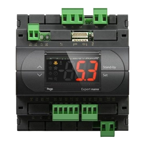
Pego EasySteam 400HUM2ESXX User manual

ELECTRONIC KIT
400HUM2ESXX / 400KHUM2ESXX
INSTALLATION MANUAL
REV. 01-11
EN

Page HUM2ESXX CONFIGURATION
INTRODUCTION
Page 2 1.1 Generality
CONFIGURATION
Page 3 2.1 Hardware configuration
Page 4 2.2 Software configuration
SETTING DEFAULT VALUES
Page 5 3.1 1st level values
Page 5 3.2 2nd level values
TABLE OF CONTENTS
CHAP. 1
CHAP. 2
CHAP. 3

Page
HUM2ESXX CONFIGURATION
GENERALITY
The Master HUM2 electronics is the core of the humidifier to which a NANO EasySTEAM display
can be coupled, enabling the displaying of the machine status, the programming and configuration
of the parameters. Connection between display and Master happens by means of a cable with 8-
poles cross-connection RJ45 telephone connector (supplied with display) to be inserted in the two
J1 references. The coupled use of Master and display is the most complete and recommended
method but not the only possible one; once configured, the Master HUM2 electronics does not
require the presence of the display and can be used independently. It is also provided with status
LED and switch (jumper) for the manual discharging of the cylinder.
The 400KHUM2ESXX electronic kit is supplied complete with “nano EasySTEAM” display unit,
masterHUM2, flat connection cable to connect master to display and TA to read the current; it has
been pre-configured for use with ES6 or ES6-OEM humidifier. This configuration can however be
changed by the user by referring to the instructions attached to the controller.
The 400HUM2ESXX electronic kit comes without the display. If needed the display can be added
further on.
PEGO order code Description
400KHUM2ESXX KIT Master HUM2 + NANO Display + cable + TA
400HUM2ESXX KIT Master HUM2 + TA
400HUMESDIS NANO DISPLAY EASYSTEAM SERIES
CHAP. 1 INTRODUCTION
1.1
2

Page HUM2ESXX CONFIGURATION
HARDWARE CONFIGURATION
Remove the cover over the front hole of the Master HUM2. The Jumper J2 with sensitivity
configuration TA can now be accessed through the hole below.
Set the jumper J2 (fig.1) in the position corresponding to the humidifier model according to 1.
(fig.1)
Jumper J2 has 2 possible positions; the jumper can be connected in position 1-2 or position 2-3.
Table 1: hardware setting correspondence through jumper J2 and humidifier size.
ES series humidifier model OEM series humidifier model J2 Position
400ES3MN 400ES3MOEMN / 400ES3MOEMCN 2-3
400ES6MN 400ES6MOEMN / 400ES6MOEMCN 2-3
400ES6N 400ES6OEMN / 400ES6OEMCN 1-2
400ES12N 400ES12OEMN / 400ES12OEMCN 2-3
400ES24N 400ES24OEMN / 400ES12OEMCN 2-3
400ES48N 2-3
2.1
CHAP.2 CONFIGURATION
3

Page
HUM2ESXX CONFIGURATION
SOFTWARE CONFIGURATION
Software is configured by setting the hidden parameter I1. This parameter allows you to vary the
nominal absorbed current value while the machine is operating. Parameter I1 is the fulcrum upon
which correct reading of amperometric absorption is developed and ensuing software processing.
In order to access this parameter, connect the NANO EasySTEAM display and keep the UP button
pressed on the controller keyboard while the machine is without electrical power.
Power the machine, again pressing the UP button until the writing I1 appears on the display (the
operation lasts approximately 10 seconds).
Press the SET button to view the set value. Keeping the SET button pressed increases or decreases
the value I1 by using the UP or DOWN keys. Release the SET button. The set value is now
memorised by the software.
To exit programming, press the UP and DOWN keys simultaneously for about 2 seconds.
Table of software setting correspondence through value I1.
ES series humidifier model OEM series humidifier model Value I1
400ES3MN 400ES3MOEMN / 400ES3MOEMCN 9
400ES6MN 400ES6MOEMN / 400ES6MOEMCN 13,5
400ES6N 400ES6OEMN / 400ES6OEMCN 6,5
400ES12N 400ES12OEMN / 400ES12OEMCN 13
400ES24N 400ES24OEMN / 400ES12OEMCN 25
400ES48N 50
Setting value I1 is fundamental for the correct functioning of the humidifier.
For the respect the values indicated in the table, including decimals.
Setting values different from those indicated and/or not corresponding with the
hardware setting of jumper J2, could cause malfunctioning or damage to the
appliance.
2.2
3
4

Page HUM2ESXX CONFIGURATION
1ST LEVEL VALUES
1. 1st level default values are the same for all humidifier models.
2. To access the first level programming menu follow the instructions below:
- Simultaneously keep keys UP (5) and DOWN (6) pressed until the first programming
variable appears on the display.
- Release keys (5) and (6)
- Select the variable to amend using key (5) or key (6).
- After having selected the wanted variable it will be possible:
- To display its setting by pressing the SET key
- To amend the setting by keeping the SET key pressed and by pressing one of the (5) or (6)
keys. To exit the menu once the configuration values are set, simultaneously keep keys (5) and
(6) pressed for a few seconds until the size displayed before entry to programming appears
again, e.g. steam output or absorbed current. Memorisation of the amendments made to the
variables will happen automatically when exiting the configuration menu.
VAR. MEANING VALUES DEFAULT
all models
Pr Steam output percentage 20 ÷ 100 % 100 %
Bp Proportional band 1 ÷ 20 Rh% 10 %
StC Max humidity set point in channel. 25 ÷ 99 Rh% 99%
r0 Max humidity set differential in channel. 1 ÷ (StC – 20) Rh% 50%
r1 Temperature differential referred to set point. 0.2 – 10°C 2°C
UrC Humidity value read by the channel probe 0-100% read only
2ND LEVEL VALUES
1. Set the 2nd level default values referring to the humidifier model upon which the kit will be
mounted, following the summarised table carried hereafter (the values shown are the only values
to be modified since they are different from one size to another):
2. To access second level programming, keep the UP (5), DOWN (6) and WATER
DISCHARGE keys pressed for a few seconds. When the first programming variable appears,
the system automatically switches to stand-by.
- Select the variable to amend using key (5) or key (6).
- After having selected the wanted variable it will be possible:
- To display its setting by pressing the SET key
- To amend the setting by keeping the SET key pressed and by pressing one of the (5) or (6)
keys.
CHAP. 3 SETTING DEFAULT VALUES
3.2
3.1
5

Page
HUM2ESXX CONFIGURATION
- To exit the menu once the configuration values are set, simultaneously keep keys (5) and (6)
pressed for a few seconds until the cell humidity value appears again (displays 0.0 if ON/OFF).
Memorisation of the amendments made to the variables will happen automatically when exiting the
configuration menu.
Press the ON/OFF - STAND-BY key to enable the electronic control (when you enter 2nd level
programming, the humidifier automatically switches to STAND-BY mode).
DEFAULT
VAR. MEANING VALUES ES-3M
ES-6M
ES-12
ES-6 ES-24 ES-48
S0 Pump discharge duration time for deconcentration. 0.1 ÷ 12.7 s 2 2 3 5
S1 Hours of work Tenths of hours - - - -
S2 Discharges for deconcentration interval. 1 ÷ 250 min 15 15 15 15
S3 Delay time in insertion of electrodes after any pump discharge. 1 ÷ 12 s 2 2 2 2
S4 Water discharge after inactivity 0 – 24 h 1 1 1 1
S5 Minimum current differential between one water charge and
another. 0.2 ÷ 10 A 1 0,7 1 1
S6 Percentage of discharge pump activation 1 ÷ 50 % 25 25 20 15
S7 Pump discharge duration time for overcurrent. 0.1 ÷ 5.0 s 0.5 0.5 0.5 0.5
S8 Minimum current differential for water charge. 0.0 ÷5.0 A 0.1 0.1 0.3 0.5
S9 Functioning setting 0 ÷ 8 0 0 0 0
S10 Discharge Test 0 ÷ 1 1 1 1 1
CA1 Humidity probe calibration -20 % ÷ 20 % 0 % 0 % 0 % 0 %
CA2 Channel humidity probe calibration -20 % ÷ 20 % 0 % 0 % 0 % 0 %
CA3 NTC probe value correction -10.0÷ 10.0 °C 0,0 0,0 0,0 0,0
t1 Delay in seconds to humidifier re-start 0-240 s 10 s 10 s 10 s 10 s
t2 Functioning time ON for essence. 1-30 s 2 s 2 s 2 s 2 s
t3 Functioning time OFF for essence. 0-99 min 5 min 5min 5min 5 min
t4 Timer for manual insertion outlet fans. 0-24 hrs 0=Dis. 0 0 0 0
In2 Digital input In2 and activation status setting. 0 ÷ 9 1 1 1 1
In3 POWERED input In3 and activation status setting. 0 ÷ 9 0 0 0 0
dO4 Digital output dO4 functioning setting. -3 ÷ 4 1 1 1 1
dO5 Digital output dO5 functioning setting. -3 ÷ 4 0 0 0 0
HSE Maximum value attributable to set point 0 ÷ 99 99 99 99 99
Ad MODBUS-RTU network address or master-slave
configuration. 0 ÷ 247 1 1 1 1
MS Master-Slave setting (with MS=0 modbus is enabled) 0 ÷ 6 0 0 0 0
rEL release software MASTER read only 11 11 11 11
6

Page HUM2ESXX CONFIGURATION
PEGO s.r.l. HUMIDIFIERS DIVISION
Via Piacentina, 6/b 45030 Occhiobello ROVIGO – ITALY
Tel. +39 0425 762906 Fax +39 0425 762905
Dealer:
Document code: 400 HUM2ESXX ELECTRONIC KIT rel. 01-11 ITA
PEGO s.r.l. reserves the right to make amendments to this use manual at any moment.
This manual suits for next models
2
Other Pego Controllers manuals

Pego
Pego PLUS 100 AB User manual

Pego
Pego PLUS 100 THR User manual

Pego
Pego ECP200 BASE Series User manual

Pego
Pego 200NDIN3RK Operating instructions

Pego
Pego 200PEVS01 Operating instructions

Pego
Pego VISION SC600 User manual

Pego
Pego 200NDINFSC Operating instructions

Pego
Pego Vision Touch Wellness Operating instructions

Pego
Pego ECP200 Expert d7.5 User manual

Pego
Pego ECP200 Expert d7.5 User manual