MDT Technologies SCN-RTRGW.02 User manual

MDT technologies GmbH • 51766 Engelskirchen • Papiermühle 1 • Germany
State 05/2022 Version V1.0
Technical Manual
MDT
Glass Room Temperature Controller
Smart
SCN-RTRGW.02
SCN-RTRGS.02
Further Documents:
Datasheet:
https://www.mdt.de/EN_Downloads_Datasheets.html
Assembly and Operation Instructions:
https://www.mdt.de/EN_Downloads_Instructions.html
Solution Proposals for MDT products:
https://www.mdt.de/EN_Downloads_Solutions.html

Technical Manual
Glass Room Temperature Controller Smart SCN-RTRGx.02
MDT technologies GmbH • 51766 Engelskirchen • Papiermühle 1 • Germany
Phone: +49-2263-880 • knx@mdt.de • www.mdt.de
2
2
1 Content
2Overview .........................................................................................................................5
2.1 Overview devices.................................................................................................................. 5
2.2 Special functions .................................................................................................................. 6
2.3 Exemplary Circuit Diagram ................................................................................................... 8
2.4 Structure & Handling ............................................................................................................ 8
2.5 Commissioning ..................................................................................................................... 9
3Communication objects ..................................................................................................10
3.1 Standard settings of the communication objects............................................................... 10
4Reference ETS-Parameter ..............................................................................................16
4.1 General Settings .................................................................................................................16
4.2 Display settings...................................................................................................................18
4.2.1 Representation ...........................................................................................................18
4.2.2 Adaption to ambience.................................................................................................18
4.2.3 Representation of the controller ................................................................................ 21
4.2.4 User-defined colours .................................................................................................. 22
4.3 Info display .........................................................................................................................23
4.3.1 Representation in Standby .........................................................................................23
4.3.2 Status value 1-3.......................................................................................................... 26
4.4 Temperature/Ventilation ....................................................................................................27
4.4.1 Temperature measurement........................................................................................27
4.4.2 Temperature Controller ..............................................................................................29
4.4.2.1 Setpoints, Operating Modes & Priorities ................................................................31
4.4.2.1.1 Dependent on comfort setpoint (basic) ...........................................................31
4.4.2.1.2 Independent setpoints ....................................................................................34
4.4.2.1.3 Priority of the operating modes ....................................................................... 35
4.4.2.2 Operating mode switchover (Mode selection)........................................................35
4.4.2.3 HVAC Status objects ...............................................................................................37
4.4.2.4 Operating mode after reset .................................................................................... 39
4.4.2.5 Setpoint shift...........................................................................................................40
4.4.2.6 Comfort extension with time ..................................................................................43
4.4.2.7 Lock objects ............................................................................................................44
4.4.2.8 Object for Heating/Cooling request........................................................................ 44
4.4.2.9 Reference control ...................................................................................................45

Technical Manual
Glass Room Temperature Controller Smart SCN-RTRGx.02
MDT technologies GmbH • 51766 Engelskirchen • Papiermühle 1 • Germany
Phone: +49-2263-880 • knx@mdt.de • www.mdt.de
3
3
4.4.2.10 Flow temperature limitation ...............................................................................49
4.4.2.11 Limit temperature of cooling medium ................................................................ 50
4.4.2.12 Alarms.................................................................................................................51
4.4.2.13 Window contact .................................................................................................. 52
4.4.2.14 Diagnosis.............................................................................................................54
4.4.3 Extension unit .............................................................................................................55
4.4.4 Controller parameter ..................................................................................................57
4.4.4.1 PI-control continuous.............................................................................................58
4.4.4.2 PI control switching (PWM) ....................................................................................60
4.4.4.3 2-step control (switching) ......................................................................................62
4.4.4.4 Direction of controller.............................................................................................63
4.4.4.5 Additional settings for Heating & Cooling mode.....................................................63
4.4.4.6 Additional level ....................................................................................................... 65
4.4.5 Ventilation control ......................................................................................................66
4.4.5.1 Step switch bit coded ............................................................................................. 66
4.4.5.2 Step Switch –binary coded ....................................................................................72
4.4.5.3 Step switch simple..................................................................................................73
4.4.5.4 Step switch as Byte................................................................................................. 74
4.5 Buttons ............................................................................................................................... 75
4.5.1 Button settings ...........................................................................................................75
4.5.2 Identical parameters ..................................................................................................75
4.5.2.1 Identical parameter –Lock object..........................................................................75
4.5.2.2 Identical parameter –Button/Object description..................................................76
4.5.2.3 Identical parameter –Representation on the display............................................76
4.5.3 Buttons 1/2 .................................................................................................................78
4.5.3.1 Mode selection (internal connection).....................................................................79
4.5.3.2 Ventilation control direct operation (internal connection)..................................... 81
4.5.3.3 OFF (control value = 0%) (internal connection) .....................................................83
4.5.3.4 Switchover Heating/Cooling (internal connection)................................................. 84
4.5.3.5 Basic function –Switch........................................................................................... 85
4.5.3.5.1 Switch with the Two-button function ..............................................................85
4.5.3.5.2 Switch with the Single-button function ........................................................... 86
4.5.3.6 Basic function –Switch/Send values short/long (with 2 objects)..........................87
4.5.3.7 Basic function –Dimming.......................................................................................89
4.5.3.8 Basic function –Blinds/Shutter..............................................................................91
4.5.3.9 Basic function –Send Status.................................................................................. 93
4.5.3.10 Basic function –Send value................................................................................ 94

Technical Manual
Glass Room Temperature Controller Smart SCN-RTRGx.02
MDT technologies GmbH • 51766 Engelskirchen • Papiermühle 1 • Germany
Phone: +49-2263-880 • knx@mdt.de • www.mdt.de
4
4
4.5.4 Buttons 3/4 .................................................................................................................95
4.5.4.1 Buttons 3/4 –Temperature shift as a controller.................................................... 95
4.5.4.1.1 Controller: Depending on setpoint Comfort (basic).........................................95
4.5.4.1.2 Controller: Independent setpoints ..................................................................96
4.5.4.2 Buttons 3/4 –Temperature shift as extension unit ...............................................97
4.6 Status LEDs.........................................................................................................................99
4.6.1 LED basic settings.......................................................................................................99
4.6.2 LED 1-4 .....................................................................................................................100
4.6.2.1 Priority...................................................................................................................103
4.6.2.2 Request external object cyclically........................................................................104
5Index........................................................................................................................... 105
5.1 Register of illustrations.....................................................................................................105
5.2 List of tables......................................................................................................................107
6Appendix ..................................................................................................................... 110
6.1 Statutory requirements ....................................................................................................110
6.2 Disposal ............................................................................................................................110
6.3 Assembly ..........................................................................................................................110
6.4 History...............................................................................................................................110

Technical Manual
Glass Room Temperature Controller Smart SCN-RTRGx.02
MDT technologies GmbH • 51766 Engelskirchen • Papiermühle 1 • Germany
Phone: +49-2263-880 • knx@mdt.de • www.mdt.de
5
5
2 Overview
2.1 Overview devices
The description refers to the following devices (order number in bold):
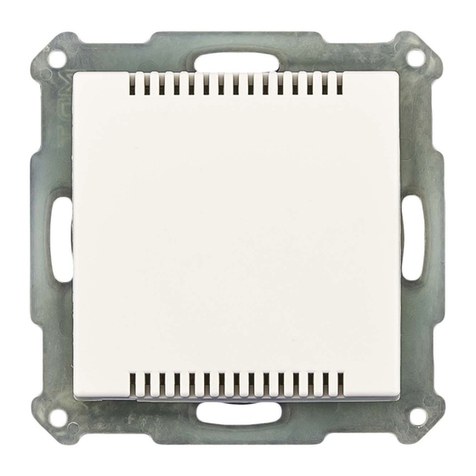
•SCN-RTRGW.02, Glass Room Temperature Controller Smart, white
•with colour display, temperature sensor and 4 sensor areas
•SCN-RTRGS.02, Glass Room Temperature Controller Smart, black
•with colour display, temperature sensor and 4 sensor areas

Technical Manual
Glass Room Temperature Controller Smart SCN-RTRGx.02
MDT technologies GmbH • 51766 Engelskirchen • Papiermühle 1 • Germany
Phone: +49-2263-880 • knx@mdt.de • www.mdt.de
6
6
2.2 Special functions
Comfortable room temperature controller with temperature sensor
The range of functions of the Glass Room Temperature Controller Smart extends from simple
heating control to the complete air-conditioning of a room. The operating modes "Heating",
"Cooling" and "Heating and Cooling" are available for this purpose. The 2-point control, a switching
PI control (PWM) or the continuous PI control can be selected. The Glass Room Temperature
Controller Smart supports single- and dual-circuit systems. This makes it possible to control air-
conditioning systems with a common pipe system as well as systems with two separate pipe
systems for Heating/Cooling. The temperature is measured by an integrated temperature sensor.
The parameter "Sensor internal/external" can be used to activate an additional measuring
extension. This makes it possible to form an average value from an internal and an external sensor.
If the external sensor fails, the internal sensor is set to 100%. It is also possible to activate an
upper and a lower message value, which emits a 1-bit message if the value exceeds or falls below
the setpoint. Furthermore, it is possible to set the setpoint either depending on the basic Comfort
value or via independent setpoints.
Extension operation
In extension unit operation, the Glass Room Temperature Controller Smart can be used, for
example, in combination with the MDT Heating Actuator, or as an additional secondary unit at a
different position. The display can be used to show all relevant functions and the internal buttons
can be used for control (operating mode changeover, setpoint shift).
Ventilation control
The integrated ventilation control enables fans to be controlled manually in up to 4 levels, via the
control value of the temperature controller, by means of the temperature difference between the
setpoint and actual value or via the relative humidity. Furthermore, the "Day/Night" function
provides for the individual setting of the ventilation according to the time of day. For example, the
ventilation control runs in up to 4 levels during "Day", depending on the requirements, and a
maximum of two levels are available in "Night" mode, to avoid disturbing noises and draughts. A
sticking protection function is available to protect the ventilation system. The behaviour of the lock
function can be set specifically.
Plain text diagnosis
The unit has a 14-byte object with which a variety of messages can be sent in plain text as status on
the bus.
Active colour display
The brightness adjusts automatically to the environment or can be changed continuously via a 1-
byte (%) object. In addition, the current display brightness can be sent to the bus as a 1-byte (%)
object and made available to other devices. The display (white text on black background or inverted)
can be set individually for "Day" and "Night" and the colours of the symbols can be changed.
Info-Display
Up to 4 status elements can be displayed for standby mode. These status elements can visualise
any values of the KNX bus as well as the time or 14-byte status texts.
Direct operating functions via buttons on the unit
Four buttons are available on each unit. The buttons 1/2 can be configured both individually and in
pairs. Here, internal functions relating to temperature control or ventilation control as well as
external functions such as "Switching", "Dimming", "Blind/Shutter" or "Send value" can be
executed directly. Buttons 3/4 are permanently set to "Temperature shift".
Technical Manual
Glass Room Temperature Controller Smart SCN-RTRGx.02
MDT technologies GmbH • 51766 Engelskirchen • Papiermühle 1 • Germany
Phone: +49-2263-880 • knx@mdt.de • www.mdt.de
7
7
RGB Status LEDs
Each of the 4 status LEDs can react to the operation, an internal or external object. The display
behaviour can be set separately for "Day" and "Night".
Long Frame Support
Support of sending longer telegrams and thus the integration of more user data per telegram. This
significantly shortens the programming time (from ETS5).
Requirement: The use of a programming interface which supports the transmission of long frames,
e.g., MDT SCN-USBR.02 or SCN-IP000.03/SCN-IP100.03.
Updateable via DCA
With the help of the MDT Update Tool, the devices can be updated if necessary.

Technical Manual
Glass Room Temperature Controller Smart SCN-RTRGx.02
MDT technologies GmbH • 51766 Engelskirchen • Papiermühle 1 • Germany
Phone: +49-2263-880 • knx@mdt.de • www.mdt.de
8
8
2.3 Exemplary Circuit Diagram
Figure 1: Exemplary circuit diagram
2.4 Structure & Handling
The following picture shows the structure of the Glass Room Temperature Controller Smart:
Figure 2: Structure & Handling
1, 2, 3, 4 = Sensor areas for operating the button functions
5, 6 = Hidden sensor areas (to enter programming mode)
7 = RGB status display
8 = Bus connection terminal
After pressing the sensor buttons 5 and 6, programming mode is indicated by information in the
display and by the status LEDs flashing red.

Technical Manual
Glass Room Temperature Controller Smart SCN-RTRGx.02
MDT technologies GmbH • 51766 Engelskirchen • Papiermühle 1 • Germany
Phone: +49-2263-880 • knx@mdt.de • www.mdt.de
9
9
2.5 Commissioning
After wiring the unit, the physical address is assigned, and the application is programmed:
(1) Connect the programming interface with the bus, e.g. with MDT USB Interface.
(2) Switch-on bus voltage.
(3) Activate programming mode by actuating the sensor areas 5 and 6 on the unit
simultaneously (as soon as the unit is in programming mode, this is shown in the display.
Status LEDs on the right and left of the unit light up red alternately).
(4) Loading of the physical address out of the ETS-Software by using the interface (The display
changes to normal mode as soon as this is successfully completed).
(5) Loads the application with the desired parameterization (programming progress is shown in
the display). Switches to normal operation as soon as this has been successfully completed.
(6) If the device is enabled, you can test the requested functions (also possible by using the
ETS-Software).

Technical Manual
Glass Room Temperature Controller Smart SCN-RTRGx.02
MDT technologies GmbH • 51766 Engelskirchen • Papiermühle 1 • Germany
Phone: +49-2263-880 • knx@mdt.de • www.mdt.de
10
10
3 Communication objects
3.1 Standard settings of the communication objects
Standard settings –Temperature controller
No.
Name
Object function
Length
C
R
W
T
U
0
Setpoint setting
Preset setpoint
2 Byte
X
X
0
Setpoint setting
Preset setpoint
2 Byte
X
X
X
1
(Basic) Comfort setpoint
Preset setpoint
2 Byte
X
X
1
Comfort
Preset setpoint
2 Byte
X
X
1
Combination object (Heating)
Preset setpoint
8 Byte
X
X
1
Combination object
Preset setpoint
8 Byte
X
X
2
Standby
Preset setpoint
2 Byte
X
X
3
Night
Preset setpoint
2 Byte
X
X
4
Frost protection
Preset setpoint
2 Byte
X
X
4
Heat protection
Preset setpoint
2 Byte
X
X
5
Combination object (Cooling)
Preset setpoint
8 Byte
X
X
6
Current setpoint
Send setpoint
2 Byte
X
X
X
6
Current setpoint
Receive setpoint
2 Byte
X
X
X
X
7
Manual setpoint shift
Increase / Decrease (2Byte)
2 Byte
X
X
7
Manual setpoint shift
Increase / Decrease (2Byte)
2 Byte
X
X
X
7
Manual setpoint shift
Increase / Decrease (1Byte)
1 Byte
X
X
X
8
Manual setpoint shift
Increase / Decrease (1Byte)
1 Byte
X
X
8
Manual setpoint shift
Increase / Decrease (1=+/0=-)
1 Bit
X
X
8
Manual setpoint shift
Increase / Decrease (1=+/0=-)
1 Bit
X
X
9
Setpoint shift
Send status
2 Byte
X
X
X
9
Setpoint shift
Receive status
2 Byte
X
X
X
X
10
Control value Heating
Send control value
1 Byte
X
X
X
10
Control value Heating
Send control value
1 Bit
X
X
X
10
Control value Heating/Cooling
Send control value
1 Byte
X
X
X
10
Control value Heating/Cooling
Send control value
1 Bit
X
X
X
11
Control value Cooling
Send control value
1 Byte
X
X
X
11
Control value Cooling
Send control value
1 Bit
X
X
X
12
Control value Heating/Cooling
Send status
1 Byte
X
X
X
12
Control value Heating
Send status
1 Byte
X
X
X
12
Control value Heating/Cooling
Receive status
1 Byte
X
X
X
X
12
Control value Heating
Receive status
1 Byte
X
X
X
X
13
Control value Cooling
Send status
1 Byte
X
X
X
X
13
Control value Cooling
Receive status
1 Byte
X
X
X
X
X
14
Control value additional Heating
Send control value
1 Bit
X
X

Technical Manual
Glass Room Temperature Controller Smart SCN-RTRGx.02
MDT technologies GmbH • 51766 Engelskirchen • Papiermühle 1 • Germany
Phone: +49-2263-880 • knx@mdt.de • www.mdt.de
11
11
15
Mode selection
Select mode
1 Byte
X
X
15
Mode selection
Send mode
1 Byte
X
X
16
Comfort mode
Comfort extension
1 Bit
X
X
17
Comfort mode
Switch mode
1 Bit
X
X
18
Night mode
Switch mode
1 Bit
X
X
19
Frost protection mode
Switch mode
1 Bit
X
X
19
Heat protection mode
Switch mode
1 Bit
X
X
19
Frost/Heat protection mode
Switch mode
1 Bit
X
X
20
DPT_HVAC Mode
Send controller status
1 Byte
X
X
X
20
DPT_HVAC Status
Send controller status
1 Byte
X
X
X
20
DPT_HVAC Mode
Receive controller status
1 Byte
X
X
X
X
20
DPT_HVAC Status
Receive controller status
1 Byte
X
X
X
X
21
DPT_HVAC Status
Send controller status
1 Byte
X
X
X
21
DPT_HVAC Mode
Send controller status
1 Byte
X
X
X
21
RHCC Status
Send controller status
2 Byte
X
X
X
21
DPT_RTC combination status
Send controller status
2 Byte
X
X
X
21
DPT_RTSM combination status
Send controller status
1 Byte
X
X
X
22
Frost alarm
Send alarm
1 Bit
X
X
X
23
Heat alarm
Send alarm
1 Bit
X
X
X
24
Flow temperature Heating
Receive measured value
2 Byte
X
X
X
25
Surface temperature Cooling
Receive measured value
2 Byte
X
X
X
25
Dew point alarm
Receive alarm
1 Bit
X
X
X
26
Diagnosis
Status
14 Byte
X
X
X
27
Window contact input
0=closed / 1=open
1 Bit
X
X
X
X
27
Window contact input
1=closed / 0=open
1 Bit
X
X
X
X
28
Lock object Heating
Lock control value
1 Bit
X
X
X
X
X
29
Lock object Cooling
Lock control value
1 Bit
X
X
X
X
X
30
Dummy
31
Dummy
32
Toggle Heating/Cooling
0=Cooling / 1=Heating
1 Bit
X
X
33
Status Heating/Cooling
0=Cooling / 1=Heating
1 Bit
X
X
X
34
Heating request
Send request
1 Bit
X
X
X
35
Cooling request
Send request
1 Bit
X
X
X
36
Outside temperature /
Reference value
Receive measured value
2 Byte
X
X
37
Reference control
Reference value in Lux
2 Byte
37
Reference control
Reference value in percent
1 Byte
38
Reference control
Status
1 Bit
X
X
X
39
Reference control
Lock
1 Bit
X
X
Table 1: Communication objects –Temperature controller

Technical Manual
Glass Room Temperature Controller Smart SCN-RTRGx.02
MDT technologies GmbH • 51766 Engelskirchen • Papiermühle 1 • Germany
Phone: +49-2263-880 • knx@mdt.de • www.mdt.de
12
12
Standard settings - Ventilation control
No.
Name
Object function
Length
C
R
W
T
U
42
Ventilation control
Lock
1 Bit
X
X
43
Ventilation control
Level 1
1 Bit
X
X
X
43
Ventilation control
Bit 0
1 Bit
X
X
X
44
Ventilation control
Level 2
1 Bit
X
X
X
44
Ventilation control
Bit 1
1 Bit
X
X
X
44
Ventilation control
Level 1+2
1 Bit
X
X
X
45
Ventilation control
Level 3
1 Bit
X
X
X
45
Ventilation control
Bit 2
1 Bit
X
X
X
45
Ventilation control
Level 1+2+3
1 Bit
X
X
X
46
Ventilation control
Level 4
1 Bit
X
X
X
46
Ventilation control
Level 1+2+3+4
1 Bit
X
X
X
47
Ventilation control
1Byte status ventilation level
1 Byte
X
X
X
48
Ventilation control
Control value
1 Byte
X
X
X
X
49
Ventilation control
Object Priority
1 Bit
X
X
50
Ventilation control
Switch Automatic
1 Bit
X
X
X
X
51
Ventilation control
Change ventilation levels
manually (+/-)
1 Bit
X
X
X
52
Ventilation control
Manual ventilation control
1 Byte
X
X
53
Ventilation control
Status ventilation active
1 Bit
X
X
X
54
Ventilation control
Status Automatic
1 Bit
X
X
X
55
Ventilation control
Relative air humidity input
2 Byte
X
X
X
X
Table 2: Communication objects –Ventilation control
Standard settings - Temperature measurement
No.
Name
Object function
Length
C
R
W
T
U
58
Temperature
Send measured value
2 Byte
X
X
X
59
Temperature
External sensor input
2 Byte
X
X
X
X
60
Temperature
Maximum value exceeded
1 Bit
X
X
X
61
Temperature
Minimum value fallen below
1 Bit
X
X
X
Table 3: Communication objects –Temperature measurement

Technical Manual
Glass Room Temperature Controller Smart SCN-RTRGx.02
MDT technologies GmbH • 51766 Engelskirchen • Papiermühle 1 • Germany
Phone: +49-2263-880 • knx@mdt.de • www.mdt.de
13
13
Standard settings - Buttons
No.
Name
Object function
Length
C
R
W
T
U
62
Button 1:
Switch
1 Bit
X
X
X
62
Button 1:
Buttons 1/2:
Dimming On/Off
1 Bit
X
X
X
62
Button 1:
Buttons 1/2:
Blinds Up/Down
1 Bit
X
X
X
62
Buttons 1/2:
Switch On/Off
1 Bit
X
X
X
62
Button 1:
Toggle
1 Bit
X
X
X
62
Button 1:
Send status
1 Bit
X
X
X
62
Button 1:
Send value
1 Byte
X
X
X
62
Button 1:
Send percent value
1 Byte
X
X
X
62
Button 1:
Send scene
1 Byte
X
X
X
62
Button 1 short:
Switch
1 Bit
X
X
X
62
Button 1 short:
Toggle
1 Bit
X
X
X
62
Button 1 short:
Send value
1 Byte
X
X
X
62
Button 1 short:
Send percent value
1 Byte
X
X
X
62
Button 1 short:
Send scene
1 Byte
X
X
X
63
Button 1:
Buttons 1/2:
Dimming relative
4 Bit
X
X
X
63
Button 1:
Buttons 1/2:
Slat adjustment / Stop
1 Bit
X
X
X
63
Button 1:
Status for toggle
1 Bit
X
X
X
X
63
Button 1 short:
Status for toggle
1 Bit
X
X
X
X
63
Button 1 short:
Status for display
1 Bit
X
X
X
X
63
Button 1 short:
Status for display
1 Byte
X
X
X
X
64
Button 1 long:
Switch
1 Bit
X
X
X
64
Button 1 long:
Toggle
1 Bit
X
X
X
64
Button 1 long:
Send value
1 Byte
X
X
X
64
Button 1 long:
Send percent value
1 Byte
X
X
X
64
Button 1 long:
Send scene
1 Byte
X
X
X
64
Button 1:
Status for toggle
1 Bit
X
X
X
X
64
Button 1:
Status for change of direction
1 Bit
X
X
X
X
65
Button 1:
Buttons 1/2:
Status for display
1 Bit
X
X
X
X
65
Button 1:
Buttons 1/2:
Status for display
1 Byte
X
X
X
X
65
Button 1 long:
Status for toggle
1 Bit
X
X
X
X
66
Button 1:
Buttons 1/2:
Lock object
1 Bit
X
X
66
Button 1:
Operating mode switchover
Lock object
1 Bit
X
X

Technical Manual
Glass Room Temperature Controller Smart SCN-RTRGx.02
MDT technologies GmbH • 51766 Engelskirchen • Papiermühle 1 • Germany
Phone: +49-2263-880 • knx@mdt.de • www.mdt.de
14
14
66
Button 1: Ventilation control
Lock object
1 Bit
X
X
66
Button 1: Control value = 0%
Lock object
1 Bit
X
X
66
Button 1: Heating / Cooling
Lock object
1 Bit
X
X
+5
next button
72
Buttons 3/4: Setpoint shift
Lock object
1 Bit
X
X
Table 4: Communication objects –Buttons
Standard settings –Status LEDs
No.
Name
Object function
Length
C
R
W
T
U
73
LED 1
Switch
1 Bit
X
X
X
X
73
LED 1
Percent value
1 Byte
X
X
X
X
73
LED 1
Decimal value
1 Byte
X
X
X
X
+1
next LED
77
LED 1 Priority
Switch
1 Bit
X
X
X
X
+1
next LED Priority
81
LED 1
Lock object
1 Bit
X
X
X
X
92
LED
Flashing status
1 Bit
X
X
92
LED
Flashing status
1 Bit
X
X
Table 5: Communication objects –Status LEDs
Standard settings –Info display
No.
Name
Object function
Length
C
R
W
T
U
82
Status text 1
Input
14 Byte
X
X
X
X
83
Status text 2
Input
14 Byte
X
X
X
X
84
Status value 1
Switch On/Off
1 Bit
X
X
X
X
84
Status value 1
Percent value 0…100%
Value 0…255
1 Byte
X
X
X
X
84
Status value 1
Value in m/s
Value in Lux
Value in °C
Value in %
Value in ppm
Value in mA
2 Byte
X
X
X
X
+1
next Status value
91
Display
Brightness
1 Byte
X
X
91
Display
Brightness
1 Byte
X
X
X
Table 6: Communication objects –Info display

Technical Manual
Glass Room Temperature Controller Smart SCN-RTRGx.02
MDT technologies GmbH • 51766 Engelskirchen • Papiermühle 1 • Germany
Phone: +49-2263-880 • knx@mdt.de • www.mdt.de
15
15
Standard settings - General objects
No.
Name
Object function
Length
C
R
W
T
U
87
Operating
Output
1 Bit
X
X
X
88
Day/Night
Day = 1 / Night = 0
1 Bit
X
X
X
X
88
Day/Night
Night = 1 / Day = 0
1 Bit
X
X
X
X
89
Presence
Input
1 Bit
X
X
X
X
90
Button operation
Output
1 Bit
X
X
X
93
Time
Receive current value
3 Byte
X
X
X
X
94
Date
Receive current value
3 Byte
X
X
X
X
95
Time/Date
Receive current value
8 Byte
X
X
X
X
Table 7: Communication objects –General objects
The table above shows the preset default settings. The priority of the individual communications
objects and the flags can be adjusted by the user as required. The flags assign the communication
objects their respective tasks in programming, where C stands for communication, R for read, W for
write, T for transmit and U for update.

Technical Manual
Glass Room Temperature Controller Smart SCN-RTRGx.02
MDT technologies GmbH • 51766 Engelskirchen • Papiermühle 1 • Germany
Phone: +49-2263-880 • knx@mdt.de • www.mdt.de
16
16
4 Reference ETS-Parameter
4.1 General Settings
The following figure shows the menu for the general settings:
Figure 3: General settings
The following table shows the possible settings:
ETS-Text
Dynamic range
[Default value]
Comment
Startup time
2 –240 s
[2 s]
Sets the time between restart and
functional start-up of the device.
Send
„Operation“ cyclically
not active
1 min –24 h
Activation of a cyclic "in operation"
telegram.
Value for Day/Night
▪Day = 1 / Night = 0
▪Day = 0 / Night = 1
Sets the polarity for day / night
switching.
Behaviour after bus power return
Status for toggle
▪no request
▪request
Setting whether the values/objects are
to be automatically requested when the
bus voltage returns.
Object Day/Night
▪no request
▪request
Objects Time/Date
▪no request
▪request

Technical Manual
Glass Room Temperature Controller Smart SCN-RTRGx.02
MDT technologies GmbH • 51766 Engelskirchen • Papiermühle 1 • Germany
Phone: +49-2263-880 • knx@mdt.de • www.mdt.de
17
17
Language
▪German
▪English
▪French
▪Spanish
Setting the language of the diagnostic
text.
Reaction time on
keypress
▪fast
▪medium
▪slow
Defines the debounce time for a
keystroke.
Time for long push of
button
0,1 s –30 s
[0,4 s]
Defines the time for detecting a long
keystroke.
Table 8: General settings
Startup time
This time defines when the unit "boots up" after a restart (reset, reprogramming, bus voltage
recovery). This can be important if - example 1 - a bus reset is carried out. If there are many units
on a line, all units would start at the same time and load the bus. With a variable time, the units can
thus start differently.
Example 2: If Time/Date, values for changeover or Day/Night object are queried, it makes sense
that the units responsible for them start up first, this unit only a little later. This ensures that all
values are available and correct.
„Operation“
"In operation" is used to show on the bus that the unit is "alive". If activated, an ON telegram is sent
cyclically.
Value for Day/Night:
Here the polarity for day/night is defined. Regardless of this polarity, the device always starts in day
mode after reprogramming.
Language
The language for the display and the diagnostic text is set here.
Important: As of 05/2022: The diagnosis text is only displayed in German (setting: German) or
English (setting: English, French, Spanish).
The table shows the general communications objects:
Number
Name/Function
Length
Usage
87
Operation
1 Bit
Sending a cyclic "In operation" telegram
88
Day/Night
1 Bit
Receiving the status for Day/Night
90
Button activation
1 Bit
Sending a 1 when a button is pressed, e.g. for
switching on an orientation light
93
Time
3 Byte
Receiving the time
94
Date
3 Byte
Receiving the date
95
Time / Date
8 Byte
Receiving time and date via a common
combination object
Table 9: General communication objects

Technical Manual
Glass Room Temperature Controller Smart SCN-RTRGx.02
MDT technologies GmbH • 51766 Engelskirchen • Papiermühle 1 • Germany
Phone: +49-2263-880 • knx@mdt.de • www.mdt.de
18
18
4.2 Display settings
4.2.1 Representation
The following settings can be used to adjust the display:
Figure 4: Display settings –Representation
The following table shows the possible settings:
ETS-Text
Dynamic range
[Default value]
Comment
Background colour
▪Day = black; Night = black
▪Day = white; Night = black
▪Day = black; Night = white
▪Day = white; Night = white
Sets the background colour of
the display
Font size: function name
▪small
▪big
Setting the font size for the
function name.
Font size: labelling of
buttons
▪small
▪big
Setting the font size for the
button labelling.
Behaviour if the text is
too long
▪text is clipped
▪text size is reduced
Setting the behaviour when the
text cannot be displayed
completely.
Table 10: Display settings –Representation
4.2.2 Adaption to ambience
The following settings can be used to adjust the representation in the display:
Figure 5: Display settings –Adaption to ambience

Technical Manual
Glass Room Temperature Controller Smart SCN-RTRGx.02
MDT technologies GmbH • 51766 Engelskirchen • Papiermühle 1 • Germany
Phone: +49-2263-880 • knx@mdt.de • www.mdt.de
19
19
The following table shows the possible settings:
ETS-Text
Dynamic range
[Default value]
Comment
Behaviour at presence
▪Display is switched on
▪Display is switched on and
Standby is exited
Setting the behaviour for a "1"
telegram to the presence object.
Adapt display brightness
to ambience
▪not active
▪active
Setting whether the brightness is
dynamically adapted to the
ambience.
Adapt display brightness to ambience: not active
Brightness can be received via
object 91 to synchronize multiple
displays.
Fixed text.
For details see description below*.
Brightness at Day
0 –100%
[100%]
Setting a fixed brightness value in
Day mode.
Brightness at Night
0 –100%
[50%]
Setting a fixed brightness value in
Night mode.
Adapt display brightness to ambience: active
Send brightness via object
to the bus
▪not active
▪active
Setting whether the current display
brightness is sent.
Brightness
Brightness level 1 –10
[Brightness level 8]
Setting the basic brightness of the
display.
Minimum Brightness for
Day
1 –100 %
[10 %]
Setting of the brightness that
cannot be undercut during
dimming in “Day” operation.
Minimum Brightness for
Night
1 –100 %
[3 %]
Setting of the brightness that
cannot be undercut during
dimming in “Night” mode.
Valid for both settings:
Overnight shutdown in
Standby
▪not active
▪Threshold 1 (moderately
dark)
▪Threshold 2 (dark)
▪Threshold 3 (very dark)
Setting of the display behaviour for
the Night shut-off in Standby
mode.
Table 11: Display settings –Adaption to ambience
With the parameter "Behaviour at presence" it is possible to switch on the display via an object, for
example, by sending a "1" when motion is detected via a presence/motion detector. It is possible to
select whether the display is only switched on or whether the Standby mode is also exited at the
same time.
Principle of brightness adjustment:
The Glass Room Temperature Controller Smart has an internal brightness sensor and can
dynamically adjust the display brightness to the environment. The "Brightness" parameter
influences the dimming behaviour and the threshold from which the display is dimmed. The
parameter for the minimum brightness defines the absolute lowest threshold up to which the
display is dimmed.

Technical Manual
Glass Room Temperature Controller Smart SCN-RTRGx.02
MDT technologies GmbH • 51766 Engelskirchen • Papiermühle 1 • Germany
Phone: +49-2263-880 • knx@mdt.de • www.mdt.de
20
20
In the programmed state, the menu for setting the brightness can be called up by simultaneously
actuating the sensor areas 5 and 6. The brightness is set by actuating the sensor areas 3 (-) or 4 (+):
In this menu, the end user can adjust the brightness settings independently (without ETS). The
settings made are permanently stored in the unit until the next time the database is transferred.
If the parameter "Adapt display brightness to ambience" is set to "active", the following settings
are available:
If the parameter "Send brightness via object to the bus" is activated, the current brightness value
can be sent via object 91. This allows, for example, the brightness to be synchronised with other
devices.
Brightness: Defines the basic brightness of the display and influences the dimming behaviour of
the display according to the measured value for the ambient brightness.
Minimum brightness: Defines the brightness that the display has in any case. This brightness can
be set separately for "Day" mode and for "Night" mode.
*If the parameter "Adapt display brightness to ambience" is set to "not active", the following
settings are available:
Brightness at Day/Night: Defines the absolute, fixed brightness of the display in "Day" mode or in
"Night" mode.
In addition, the brightness can be controlled via the bus here. In this case, a brightness value is
received via object 91, with which, for example, the brightness is synchronised with other devices.
Application example: Several units are installed in the building. One unit serves as the "master" and
sends its current brightness value to the bus. The other devices behave like "slaves" and receive
this brightness value.
The table shows the general communication objects:
Number
Name/Function
Length
Usage
89
Presence –Input
1 Bit
Input for presence active, e.g. from a presence
detector
88
Display –Brightness
1 Byte
Receiving/sending the brightness for the display
Table 12: Communication objects –Adaption to ambience
This manual suits for next models
1
Table of contents
Other MDT Technologies Controllers manuals

MDT Technologies
MDT Technologies SCN-RT1UP.01 User manual

MDT Technologies
MDT Technologies AMI-0416.03 User manual

MDT Technologies
MDT Technologies JAL-0206.01 User manual

MDT Technologies
MDT Technologies AKH-0400.01 User manual

MDT Technologies
MDT Technologies RF-TA55A2.01 User manual

MDT Technologies
MDT Technologies BE-GT2TW.01 User manual

MDT Technologies
MDT Technologies JAL-01UP.02 User manual

MDT Technologies
MDT Technologies AKS Series User manual

MDT Technologies
MDT Technologies KNX SCN-LCDGW.01 User manual

MDT Technologies
MDT Technologies AKK-03UP.02 User manual