Electrical Manual
VM16,17,24,25,30 Electronic Orient Spindle
SERVING YOUR METAL CUTTING NEEDS FOR MORE THAN 25 YEARS
Table Of Contents
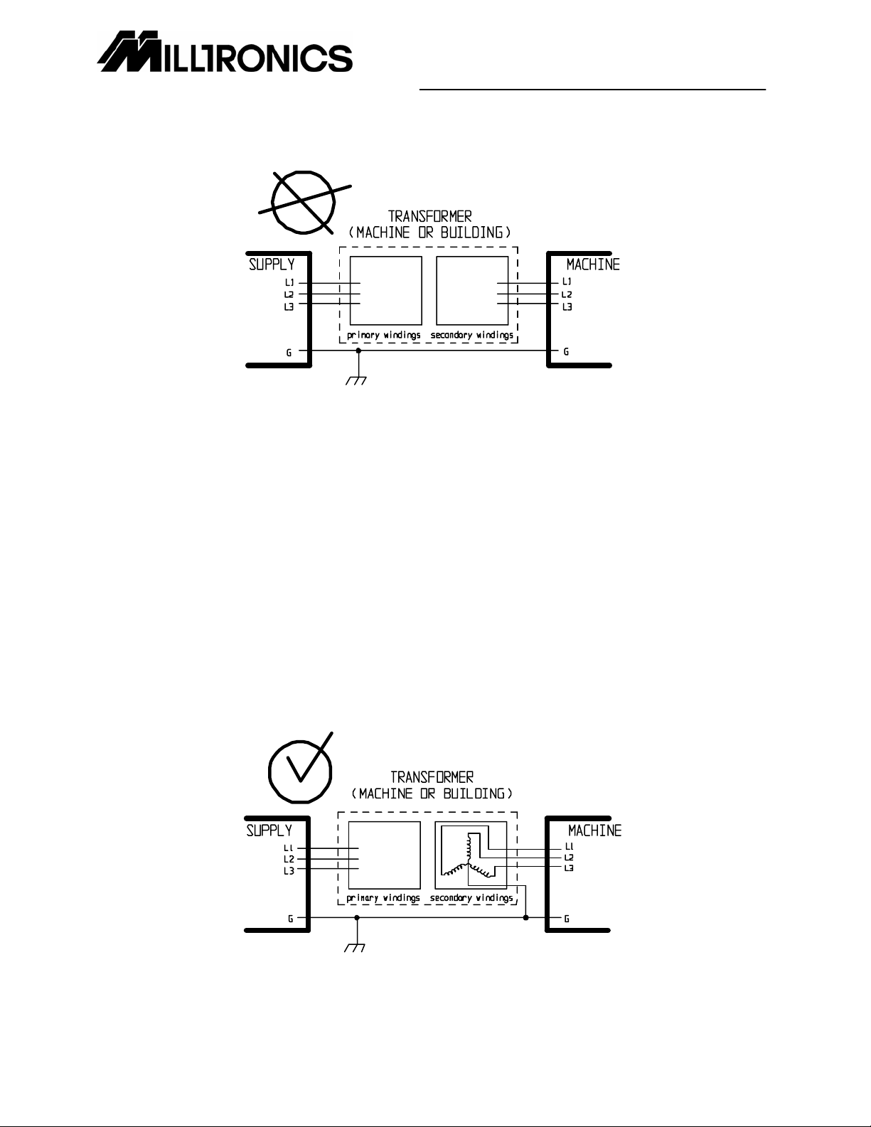
Transformer Connection Alert....................................................................................................................... v
Electrical Safety Rules ................................................................................................................................. vi
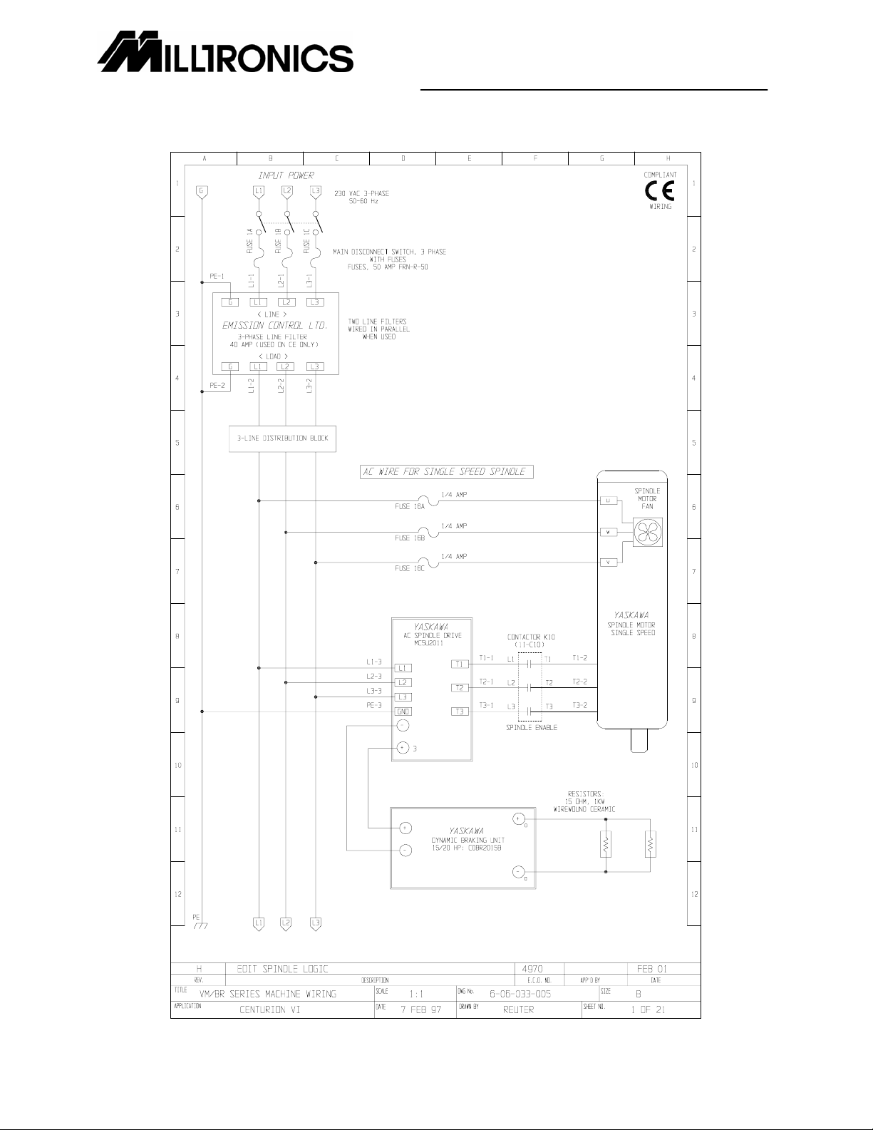
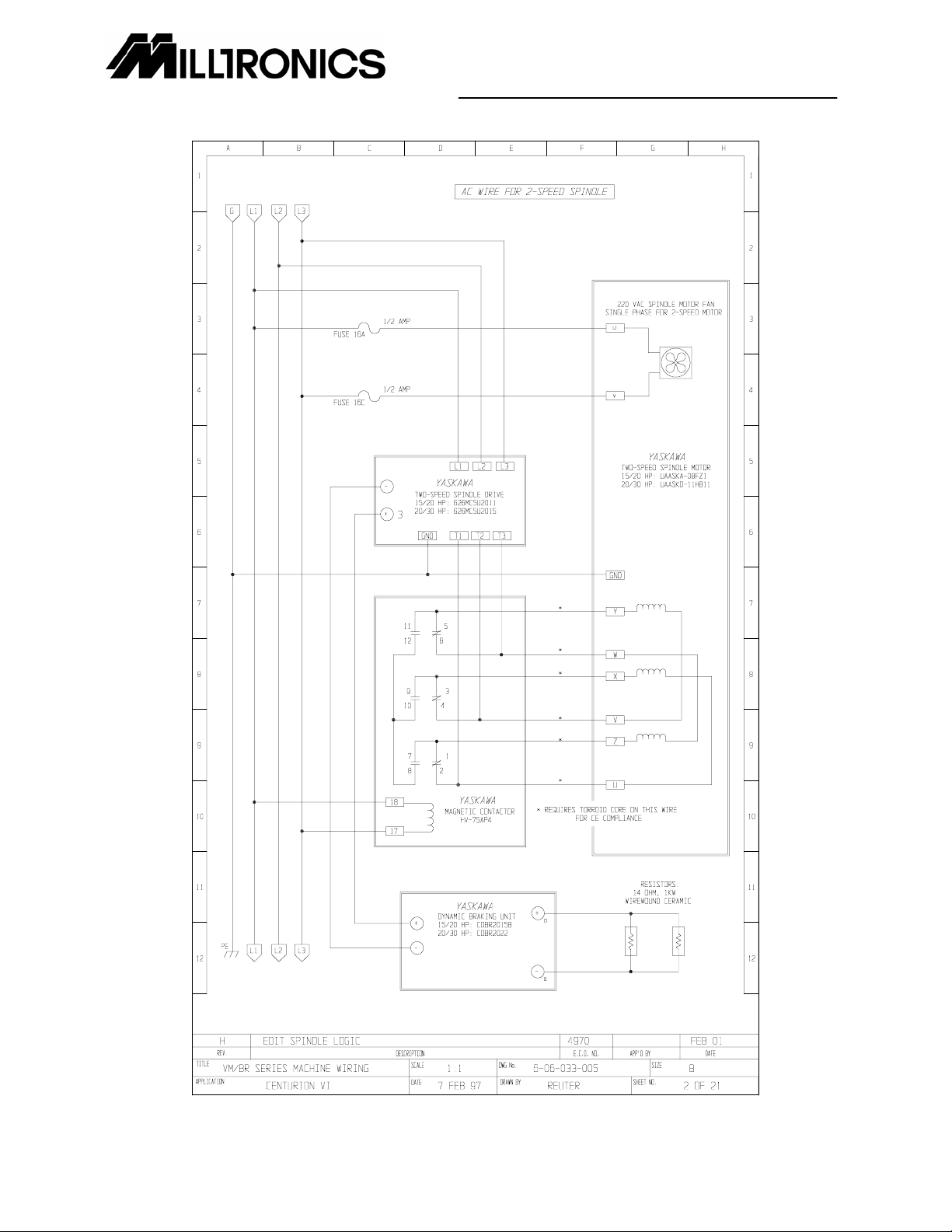
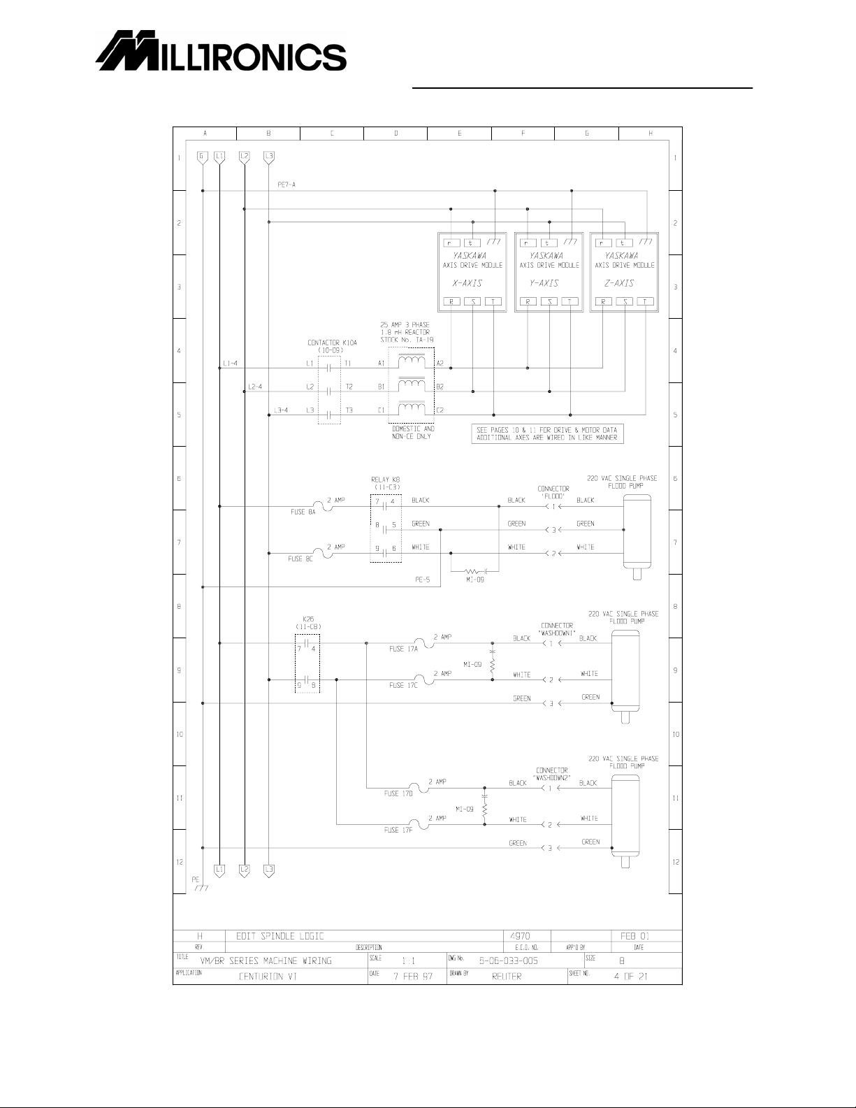
Machine Schematic....................................................................................................................................... 1
Electrical Panel Layout................................................................................................................................ 22
MC5 Spindle Drive Parameters - Single speed 15/10 HP .......................................................................... 26
MC5 Spindle Drive Parameters 22/15 HP .................................................................................................. 29
MC5 Spindle Drive Parameters 30/22 HP .................................................................................................. 32
Yaskawa Axis Drive Parameters................................................................................................................. 35
Partner VM16 & 17 X and Y Drives Model SGDB-10ADG, Z SGDB 15ADG ......................................... 35
Partner VM24 X and Y Drives Model SGDB-10ADG, Z 15ADG ............................................................. 36
Partner VM25 & 30 All Drives Model SGDB-15ADG .............................................................................. 37
Yaskawa Axis Drive Parameters for Troyke Indexers............................................................................. 38
Card Cage Gain Setting Procedure......................................................................................................... 39
Drive Setting Procedure .......................................................................................................................... 40
Centurion 6 CNC Connector Signal Listing................................................................................................. 41
Connector X-Input ................................................................................................................................... 41
Connector Y-Input ................................................................................................................................... 41
Connector Z-input.................................................................................................................................... 41
Connector A-Input ................................................................................................................................... 41
Connector X-Output................................................................................................................................. 41
Connector Y-Output................................................................................................................................. 41
Connector Z-Output................................................................................................................................. 42
Connector A-Output................................................................................................................................. 42
Connectors X, Y, Z, A and B Axis (DC Brush Drives) ............................................................................. 42
Connectors X, Y, Z, A and B Axis (Yaskawa Brushless Drives)......................................................... 42
Axis Home Connector.............................................................................................................................. 42
Spindle Drive Connector.......................................................................................................................... 43
Spindle Encoder Connector..................................................................................................................... 43
Miscellaneous Connector (Misc) ............................................................................................................. 43
Front Panel Connector (FPP) and J2 on keyboard encoder card ........................................................... 43
Power Connector ..................................................................................................................................... 43
Connector Handwheel for remote handwheel option ......................................................................... 43
Connector Tool Changer ......................................................................................................................... 43
Connector COM1 (Card Cage)................................................................................................................ 44
Connector COM2 For rigid tapping option............................................................................................... 44
Connector Floppy Disk ............................................................................................................................ 44
Connector CRT (Video) ........................................................................................................................... 44
Connectors in the CNC control box ............................................................................................................ 44
Connector CRT (Monitor Power)............................................................................................................. 44
Connector FPACC................................................................................................................................... 44
Connector P2........................................................................................................................................... 44
Keyboard DIN Connector (J1) ................................................................................................................. 45
Connectors in the Mag Box......................................................................................................................... 45
Connectors ATC1 and 1-1E .................................................................................................................... 45
Connector ATC2...................................................................................................................................... 45
Connector on +24 VDC Regulated Power Supply .................................................................................. 45
Connector COM1 (on Mag Panel) ........................................................................................................... 45
Card Cage Assembly .................................................................................................................................. 46
LCD Front Panel Assembly......................................................................................................................... 52
LCD Chassis Assembly............................................................................................................................... 54