Milnor 08PSS3401N User manual

Published Document Number: BICUUR01
• Specified Date: 20020314
• As-of Date: 20020314
• Access Date: 20020314
• Depth: detail
• Applicability: CUU
• Language Code: ENG01, Purpose: publication, Format: 1colA
Document—
Power Supply
Replacement—All
Microprocessor
Controlled Machines
Except the CBW®
PELLERIN MILNOR CORPORATION POST OFFICE BOX 400, KENNER, LOUISIANA 70063 - 0400, U.S.A.

PELLERIN MILNOR CORPORATION
BICUUR01 (Published) Book specs- Dates: 20020314 / 20020314 / 20020314 Lang: ENG01 Applic: CUU
Power Supply Replacement—All Microprocessor Controlled
Machines Except the CBW®
This instruction applies to two power supply replacement kits which cover all Milnor
microprocessor-controlled machines except the CBW®. The kits are as follows:
• 08PSS3401N—This is for older machines and contains bracketry and wire harnesses
which are only needed if the bracketry and harnesses supplied with the original equipment are
different from those in the kit.
• 08PSS3401X—This is for newer machines and does not contain bracketry or wire
harnesses. The new power supply physically matches the old.
A metal oxide varistor (MOV) and a regulating resistor are supplied with both kits. The MOV
must be installed across the new power supply's incoming power conductors, on any machine.
The resistor is used only on certain machines. It must be installed across the new power supply's
5 volt DC output conductors, as shown in Figure 2, on any applicable machine.
Please verify that all components listed in the kit parts list were supplied. Contact the Milnor
Parts Department if any items are missing.
WARNING 1 : Electrocution and Electric Shock Hazards—You can be electrocuted or
seriously injured if you come in contact with 240 VAC or 120 VAC (depending on model)
power, which is present in the processor electric box.
• Lock off and tag out power to the machine while replacing the power supply.
• Use caution while testing and adjusting the new power supply with power on.
• Do not attempt these procedures unless qualified and authorized.
CAUTION 2 : Component Damage Hazard—Electronic components will fail if not
properly connected. Warranties can be voided if failure to follow these procedures results in
damaged components.
• The ground trace on the power supply must be connected to the chassis of the machine, as
explained herein.
• The regulating resistor must be installed if the machine is a coin, single formula, System
7®or E-P Plus®washer-extractor type and omitted if any other machine type, as
explained herein.
• Carefully read and understand this instruction before proceeding.
1. Mounting the New Power Supply
Depending on the original equipment, new bracketry may be needed to accommodate the new
power supply. Whether or not this is the case, the new power supply board must be mounted as
shown in Figure 1.

Power Supply Replacement—All Microprocessor Controlled Machines Except the CBW®
PELLERIN MILNOR CORPORATION
Figure 1: Mounting the Power Supply Board
Arrangement of Mounting Hardware Legend
1. Power supply board
2. Mounting bracket, if used,
or Processor box
3. Nylon bolt, nuts and
spacer—three places
4. Metal bolt, nuts and lock
washers; nylon spacer—
one place: must be
located at one of the
grounded mounting
holes on the power
supply
1.1. Kit 08PSS3401X (for Newer Machines)—Merely swap out the old with the new power
supply. Make certain that a good connection is established between the ground trace on the
power supply board and the machine chassis, as shown in Figure 1. If the new power supply is
not a direct match for the old, contact the Milnor factory.
1.2. Kit 08PSS3401N (for Older Machines)—Various mounting brackets are supplied with
this kit. If your original equipment does not accommodate the new power supply, select the
mounting configuration that permits you to mount the new power supply in approximately the
same position as the old one.
The mounting hardware supplied with the kit attaches the power supply to its mounting bracket.
Hardware to attach the mounting bracket to the machine is not supplied with the kit. Use any
appropriately sized bolts, nuts and lock washers or self-tapping screws.
Recommended hardware installation is as follows:
1. If a mounting bracket will be used, determine how it will be attached. Carefully prepare the
Processor box as required to accept it, but do not install it until step 3.
2. Attach the power supply to the mounting bracket or directly to the Processor box, as shown in
Figure 1. One of the four bolts supplied with the kit is metallic. This bolt must be placed in
one of the two grounded mounting holes on the power supply ( hole through a metallic trace
on the power supply's printed circuit). Ensure that the power supply is grounded to the
mounting bracket or Processor box by scraping the paint from around the hole on the bracket
or box with the metallic bolt. Be sure the metal nut and lock washer do not touch any other
component.

PELLERIN MILNOR CORPORATION
3. If a mounting bracket was used, install this assembly in the Processor box. Ensure that the
mounting bracket is grounded to the Processor box by scraping the paint from around one
pair of adjoining mounting holes on the bracket and the Processor box.
2. Electrical Connections
The procedure for making electrical connections will vary somewhat with the kit supplied, type
of machine, and the type of power supply being replaced. However, the schematic shown in
Figure 2 applies to all situations. (Older machines may use different wire color codes, but the pin
numbers will be the same as shown in this figure.) Consult the original schematic manual for wire
colors on an older machine or contact the Milnor factory.
Notice 3 : The wire carrying -12VDC from the power supply is not used on washer-extractors
with the Milnor System 7 control, or those with model numbers ending in C4A or M4A.
• When this wire is not used, terminate it with a wire nut to prevent shorting.
• Wire V3 is required if the machine is equipped with an analog-to-digital board, as for
sensing temperature or water level.
• Wire V3 is required if the machine is equipped with a digital-to-analog board, usually
used to control the motor inverter on some variable-speed machines, and modulating
steam and gas valves on dryers and textile machines.

Power Supply Replacement—All Microprocessor Controlled Machines Except the CBW®
PELLERIN MILNOR CORPORATION
Figure 2: Processor-to-Power Supply-to-Power Source Electrical Connections
Schematic Diagram
Legend
1. Processor board
2. 10-pin connector on processor board (MTA1 or MTA31 or 1MTA31)
3a. Wire designation (printed on wire and shown in machine electrical schematics)
3b. Possible wire colors if replacing old style “black box” power supply
4. 15 ohm, 3 watt regulating resistor used on System 7®and E-P Plus®washer-extractors only.
5a. Wire designation
5b. Wire colors on six-pin connector wire harness supplied with kit. Your existing wire harness may
be the same.
6. Six-pin connector (processor board side)
7. New power supply
8. Five pin connector (incoming power side)
9a. Wire designation
9b. Wire colors on five-pin connector wire harness supplied with kit
10. Metal oxide varister (MOV)
Observing caution statement 2 and referring to Figure 2, make the electrical connections
appropriate for your machine, as follows.
2.1. Kit 08PSS3401X (for Newer Machines)—Once the power supply has been swapped out
and the electrical connectors plugged into the new power supply, all that remains is to install the
MOV, and if applicable, the resistor.
1. Install the MOV across the power supply's incoming power conductors, as shown in Figure 2.
Splice the leads of the MOV as close as possible to the connector on the power supply side.
The MOV is not polarity-sensitive.
2. Only if the machine is a coin, single formula, System 7®, or E-P Plus®washer-extractor,
install the regulating resistor, as shown in Figure 2. Again, splice the leads of the resistor as
close as possible to the connector on the power supply side. The resistor is not polarity-
sensitive.

PELLERIN MILNOR CORPORATION
2.2. Kit 08PSS3401N (for Older Machines)
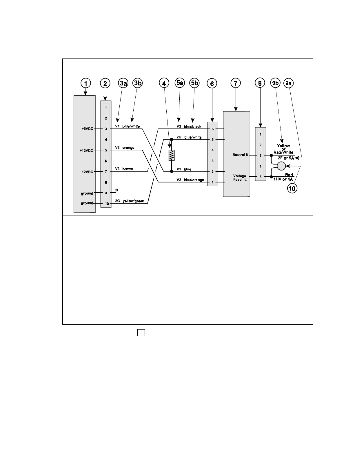
2.2.1. Power Supply-to-Power Source Connections—All Machines—Even if the old
connector (the one that was attached to the old power supply) matches the one supplied with the
kit, cut it off to facilitate installing the MOV. The MOV must be installed across the power
supply's incoming power conductors as shown in Figure 2. Splice the new harness and the leads
of the MOV to the wires from the power source using two of the white caps provided with the
kit. Match the wires as shown in Figure 2. The incoming power conductors are polarity-sensitive
but the MOV is not.
2.2.2. Processor-to-Power Suppl
y
Connections—Coin, Sin
g
le Formula, S
y
stem 7
®
and
E-P Plus®Type Washer-Extractors—The regulating resistor shown in Figure 2 must be
included when installing a new power supply on these machines. Attach this resistor across wires
2G (blue/white, ground) and V1 (blue, +5VDC) on the six-pin wire harness supplied with the kit,
using two of the white caps provided. Cut off the old connector (the one that was attached to the
old power supply) and splice the new harness to the wires from the connector on the processor
board, matching the wires as shown in Figure 2.
2.2.3. Processor-to-Power Supply Connections—Other Machines—If your original
processor-to-power supply wire harness has the same six-pin connector and same color wires as
the one supplied with the kit, you may simply attach the existing connector to the new power
supply. If not, cut off the old connector (the one that was attached to the old power supply) and
splice the new harness to the wires from the connector on the processor board using two of the
white caps provided, matching the wires as shown in Figure 2.
3. Testing and Adjusting the New Power Supply
The new power supply will need to be tested and adjusted when first installed. It may also need to
be tested and adjusted in the future, if problems with the microprocessor controller are
encountered. Adjustment instructions are provided on tag B2TAG92078, supplied with the kit.
Please install this tag inside the Processor box, for reference, and observing the precautions given
in warning statement 1 and caution statement 4 , perform the procedures explained on this
tag.
CAUTION 4 : Machine Malfunction Hazard—The power supply was adjusted at the
factory for 120VAC input and will not function properly with 240VAC input until re-adjusted.
• Test and adjust as explained on the tag supplied.
— End of BICUUR01 —
This manual suits for next models
1
Table of contents
Other Milnor Power Supply manuals
Popular Power Supply manuals by other brands

BEGA
BEGA 70 567 Instructions for use

Gallagher
Gallagher 3E3446 M5800i instructions

SECO-LARM
SECO-LARM Enforcer ST-1206-1.5A Brochure & specs

Agilent Technologies
Agilent Technologies 6622A Service manual

Keysight Technologies
Keysight Technologies N69100 Series Operating and service guide

Siemens
Siemens PSC-12 installation instructions