Replacing Power Supply 08PSS3401T (for Retrofit Kits 08PSS3401N and 08PSS3401X)
PELLERIN MILNOR CORPORATION
1. Install the MOV across the power supply's incoming power conductors, as shown in Figure 3.
Splice the leads of the MOV as close as possible to the connector on the power supply side.
The MOV is not polarity-sensitive.
2. If you determined in Section 2 that the regulating resistor supplied with the kit must be used,
install it as shown in Figure 3. Again, splice the leads of the resistor as close as possible to the
connector on the power supply side. The resistor is not polarity-sensitive.
CAUTION 4 : Component damage hazard—When in use, the regulating resistor can
become hot enough to melt wire insulation.
• Ensure that any wires are well clear of the resistor.
3.2. Kit 08PSS3401N (for Older Machines)
3.2.1. Power Supply-to-Power Source Connections—All Machines—Even if the old
connector (the one that was attached to the old power supply) matches the one supplied with the
kit, cut it off to facilitate installing the MOV. The MOV must be installed across the power
supply's incoming power conductors as shown in Figure 3. Splice the new harness and the leads
of the MOV to the wires from the power source using two of the white caps provided with the
kit. Match the wires as shown in Figure 3. The incoming power conductors are polarity-sensitive
but the MOV is not.
3.2.2. Processor-to-Power Supply Connections If Resistor Supplied With the Kit Is
Used (see Section 2)—Attach this resistor across wires 2G (blue/white, ground) and V1
(blue, +5VDC) on the six-pin wire harness supplied with the kit, using two of the white caps
provided. Cut off the old connector (the one that was attached to the old power supply) and splice
the new harness to the wires from the connector on the processor board, matching the wires as
shown in Figure 3.
3.2.3. Processor-to-Power Supply Connections If Resistor Supplied With the Kit Is
Omitted (see Section 2)—If your original processor-to-power supply wire harness has the
same six-pin connector and same color wires as the one supplied with the kit, you may simply
attach the existing connector to the new power supply. If not, cut off the old connector (the one
that was attached to the old power supply) and splice the new harness to the wires from the
connector on the processor board using two of the white caps provided, matching the wires as
shown in Figure 3.
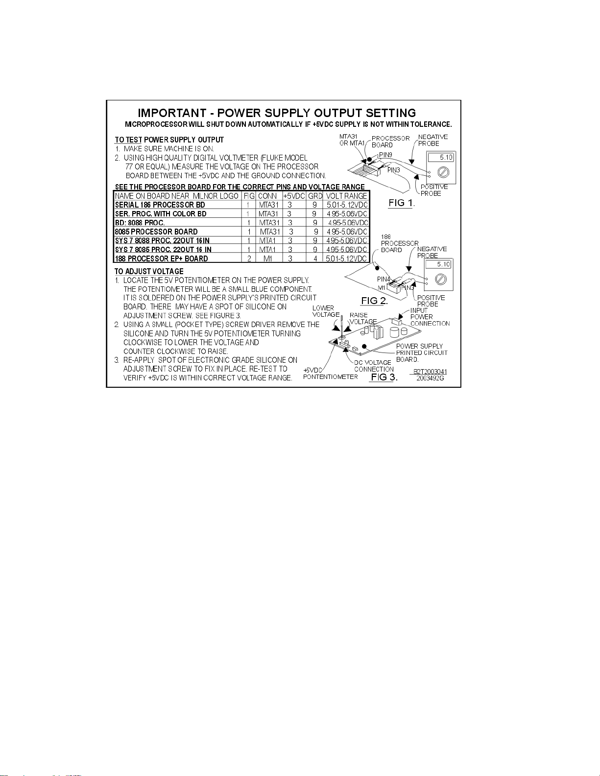
4. Setting the +5VDC Output Voltage
The +5VDC output voltage must be maintained within a narrow range. If the voltage varies from
this range, this can cause the processor board to reset, resulting in interruptions in operation. A
potentiometer (pot) is provided on the power supply board for adjusting this voltage. The
adjustment instructions are provided on tag B2T2003041, supplied with the kit and shown in
Figure 4. Affix this tag to the inside of the processor box so that it will be handy if the adjustment
procedure must be repeated in the future. As explained in the tag, the +5VDC output voltage must
be set using the pot, then the pot adjustment screw secured with a drop of electronics grade
silicon. When performing these adjustments, observe the precautions given in warning statement
1 and caution statement 5 .
CAUTION 5 : Machine Malfunction Hazard—The power supply was adjusted at the
factory for 120VAC input and will not function properly with 240VAC input until re-adjusted.
• Test and adjust as explained on the tag supplied.