Milnor MILRAIL Quick start guide

PELLERIN MILNOR CORPORATION Post Office Box 400, Kenner, Louisiana 70063–0400, U.S.A.
Installation, Parts, and
Service
MILRAIL™ Loop Soft
Sling
Manual Number: MCRUSA01
Edition (ECN): 2021132A


Pellerin Milnor Corporation i
Contents
1 General Service Information .........................................................................................................4
Limited Standard Warranty .....................................................................................................5
1.1 How to Get the Necessary Repair Components ................................................................6
1.2 Torque Requirements for Fasteners ...................................................................................6
1.2.1 Torque Values ..........................................................................................................7
1.2.1.1 Fasteners Made of Carbon Steel ..................................................................7
1.2.1.1.1 Without a Threadlocker .....................................................................7
1.2.1.1.2 With a Threadlocker ..........................................................................9
1.2.1.2 Stainless Steel Fasteners ............................................................................11
1.2.2 Preparation.............................................................................................................11
1.2.3 How to Apply a Threadlocker ...............................................................................12
1.2.3.1 Blind Holes.................................................................................................12
1.2.3.2 Through Holes ............................................................................................12
2 Rail & Netting .............................................................................................................................14
Stanchion and Beam Connections .........................................................................................15
Unistrut Support Brackets .....................................................................................................20
Rail Support Brackets ............................................................................................................22
Rail Joiner ..............................................................................................................................27
3 Bags & Cart .................................................................................................................................28
Soft Sling Bag 150 Lb. ..........................................................................................................29
Double Trolley with Auto Discharge ....................................................................................30
Cart for 150 Lb. 36” Soft Sling .............................................................................................32
4 Discharger....................................................................................................................................33
Soft Sling Bag Discharger .....................................................................................................34
5 Elevators ......................................................................................................................................37
Elevator ..................................................................................................................................38
Pneumatic Rail Elevator 24 Inch Soft Sling Bags ......................................................................46
6 Stops ............................................................................................................................................52
Flight Bar No Return .............................................................................................................53
Flight Bar Solo Stop Soft Sling Bags .........................................................................................54
Flight Bar Double Full and Empty Stops Soft Sling Bags .........................................................56
7 Sensors.........................................................................................................................................59
Trolley Detector Lift Bars .....................................................................................................60
Proximity Switch and Mounting Bracket ..............................................................................62
8 Pneumatic Valves.........................................................................................................................63
Filter Regulator Main Air ......................................................................................................64
Solenoid with Spring Return 2 Position ................................................................................65
Solenoid Spring Center 3 Position ........................................................................................66
Figures
Figure 1 The Bolts in Milnor®Equipment................................................................................7
Figure 2 Apply Threadlocker in a Blind Hole.........................................................................12
Figure 3 Apply Threadlocker in a Through Hole....................................................................13
Figure 4 Use heat for disassembly of fasteners with threadlocker..........................................13
Figure 5 Lattice Beams, Short Beams, and Net Support Beam Connections .........................15

ii Pellerin Milnor Corporation
Figure 6 Stanchions to Floor ...................................................................................................16
Figure 7 Unistrut Beam Brackets and Hardware ....................................................................16
Figure 8 Example of Unistrut Cross Bracing ..........................................................................17
Figure 9 Additional Unistrut Beam Connectors......................................................................17
Figure 10 Upper Elevator Connected to Unistrut .....................................................................18
Figure 11 Bracket Assemblies by Height and Direction...........................................................20
Figure 12 Unistrut to Unistrut Support Bracket Lengths ..........................................................21
Figure 13 Rail Slope for Design and Installation......................................................................22
Figure 14 Slope of Rail Sections...............................................................................................22
Figure 15 Bracket Assemblies by Height and Direction...........................................................23
Figure 16 Unistrut to Rail Support Brackets.............................................................................24
Figure 17 Unistrut to Rail Support Brackets, Continued ..........................................................25
Figure 18 Discharger to Rail Installation ..................................................................................34
Figure 19 Discharger Parts and Cylinder Adjustments.............................................................35
Figure 20 Elevator Components, Soft Sling & Hard Ring........................................................38
Figure 21 Hoist, Frame, & Covers ............................................................................................39
Figure 22 Rail Carrier ...............................................................................................................40
Figure 23 Double Chain Hoist Drive ........................................................................................41
Figure 24 Hoist Switch Settings................................................................................................42
Figure 25 Pneumatic Elevator Frame Components...................................................................46
Figure 26 Elevator Frame Settings and Cylinder Mounting .....................................................47
Figure 27 Carriage Sub-Assembly ............................................................................................48
Figure 28 Rail Settings, Hardware, and Alignment ..................................................................49
Figure 29 Stops and Rail Alignment .........................................................................................56
Figure 30 Stop Components and Air Cylinder Setting .............................................................57
Tables
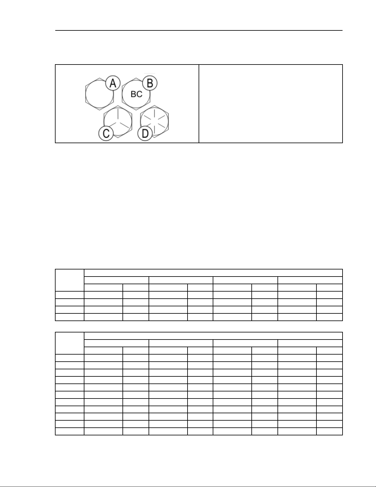
Table 1 Torque Values for Standard Fasteners with Maximum 5/16-inch Diameters and
No Lubricant ..............................................................................................................7
Table 2 Torque Values for Standard Fasteners Larger Than 5/16-inch Diameters and
No Lubricant ..............................................................................................................7
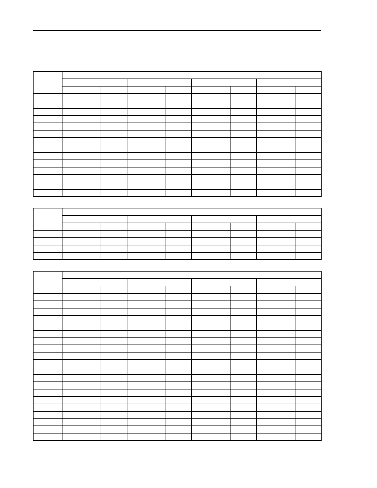
Table 3 Torque Values for Plated Fasteners with Maximum 5/16-inch Diameters and
No Lubricant ..............................................................................................................8
Table 4 Torque Values for Plated Fasteners Larger Than 5/16-inch Diameters and No
Lubricant ....................................................................................................................8
Table 5 Threadlocker by the Diameter of the Bolt (see below Note ) ....................................9
Table 6 Torque Values if You Apply LocTite 222 ..................................................................9
Table 7 Torque Values if You Apply LocTite 242 ..................................................................9
Table 8 Torque Values if You Apply LocTite 262 ................................................................10
Table 9 Torque Values if You Apply LocTite 272 (High-Temperature) ...............................10
Table 10 Torque Values if You Apply LocTite 277 ................................................................10
Table 11 Torque Values for Stainless Steel Fasteners 5/16-inch and Smaller ........................11
Table 12 Torque Values for Stainless Steel Fasteners Larger Than 5/16-inch .......................11
Table 13 Parts List—Stanchion and Beam Connections ........................................................18
Table 14 Parts List—Unistrut Support Brackets Hardware ....................................................21
Table 15 Parts List—Rail Support Brackets ...........................................................................26
Table 16 Parts List—Rail Joiner .............................................................................................27
Contents

Pellerin Milnor Corporation iii
Table 17 Parts List—Soft Sling Bag 150 Lb. .........................................................................29
Table 18 Parts List—Double Trolley with Auto Discharge ...................................................31
Table 19 Parts List—Cart for 150 Lb. 36” Soft Sling ............................................................32
Table 20 Parts List—Soft Sling Bag Discharger ....................................................................35
Table 21 Parts List—Elevator .................................................................................................43
Table 22 Parts List—Pneumatic Rail Elevator 24 Inch Soft Sling Bags .....................................49
Table 23 Parts List—Flight Bar No Return ............................................................................53
Table 24 Parts List— Flight Bar Solo Stop Soft Sling Bags .......................................................55
Table 25 Parts List—Flight Bar Double Full and Empty Stops Soft Sling Bags ........................58
Table 26 Parts List—Trolley Detector Lift Bars ....................................................................61
Table 27 Parts List—Proximity Switch and Mounting Bracket .............................................62
Table 28 Parts List—Filter Regulator Main Air .....................................................................64
Table 29 Parts List—Solenoid with Spring Return 2 Position ...............................................65
Table 30 Parts List—Solenoid Spring Center 3 Position ........................................................66
Contents

4Pellerin Milnor Corporation
1 General Service Information

6Pellerin Milnor Corporation
BNUUUM01 / 2019342 BNUUUM01 0000250121 B.3 1/2/20 2:14 PM Released
1.1 How to Get the Necessary Repair Components
BNUUUM01.C01 0000250120 A.3 B.2 B.3 1/2/20 2:14 PM Released
You can get components to repair your machine from the approved supplier where you got this
machine. Your supplier will usually have the necessary components in stock. You can also get
components from the Milnor®factory.
Tell the supplier the machine model and serial number and this data for each necessary
component:
• The component number from this manual
• The component name if known
• The necessary quantity
• The necessary transportation requirements
• If the component is an electrical component, give the schematic number if known.
• If the component is a motor or an electrical control, give the nameplate data from the used
component.
To write to the Milnor®factory:
Pellerin Milnor Corporation
Post Office Box 400
Kenner, LA 70063-0400
UNITED STATES
Telephone: 504-712-7775
Fax: 504-469-9777
Email: parts@milnor.com
BNUUUN02 / 2019125 BNUUUN02 0000222452 B.3 1/2/20 2:14 PM Released
1.2 Torque Requirements for Fasteners
BNUUUN02.C01 0000222451 A.3 B.2 B.3 1/2/20 2:14 PM Released
The document about the assembly gives the torque requirements for other fasteners. If fastener
torque specifications or threadlocker requirements in an assembly document are different
from this document, use the assembly document.
General Service Information

Pellerin Milnor Corporation 7
Figure 1. The Bolts in Milnor®Equipment
The Marks on Bolt Heads Legend
A...SAE Grades 1 and 2, ASTM A307, and stainless
steel
B...Grade BC, ASTM A354
C...SAE Grade 5, ASTM A449
D...SAE Grade 8 and ASTM A354 BD
1.2.1 Torque Values
BNUUUN02.C02 0000222449 A.3 B.2 B.3 1/2/20 2:14 PM Released
These tables give the standard dimension, grade, threadlocker, and torque requirements for fasten-
ers frequently used on Milnor®equipment.
NOTE: Data from the Pellerin Milnor®Corporation “Bolt Torque Specification” (bolt_
torque_milnor.xls/2002096).
1.2.1.1 Fasteners Made of Carbon Steel
BNUUUN02.C03 0000222448 A.3 B.2 B.3 1/2/20 2:14 PM Released
1.2.1.1.1 Without a Threadlocker
BNUUUN02.C04 0000222447 A.3 B.2 B.3 1/2/20 2:14 PM Released
Table 1. Torque Values for Standard Fasteners with Maximum 5/16-inch Diameters and No
Lubricant
Dimension
The Grade of the Bolt
Grade 2 Grade 5 Grade 8 Grade BC
Pound-Inches N-m Pound-Inches N-m Pound-Inches N-m Pound-Inches N-m
1/4 x 20 66 7101 11 143 16 126 14
1/4 x 28 76 9 116 13 163 18 – –
5/16 x 18 136 15 209 24 295 33 258 29
5/16 x 24 150 17 232 26 325 37 – –
Table 2. Torque Values for Standard Fasteners Larger Than 5/16-inch Diameters and No Lubricant
Dimension
The Grade of the Bolt
Grade 2 Grade 5 Grade 8 Grade BC
Pound-Feet N-m Pound-Feet N-m Pound-Feet N-m Pound-Feet N-m
3/8 x 16 20 27 31 42 44 59 38 52
3/8 x 24 23 31 35 47 50 68 – –
7/16 x 14 32 43 49 66 70 95 61 83
7/16 x 20 36 49 55 75 78 105 – –
1/2 x 13 49 66 75 102 107 145 93 126
1/2 x 20 55 75 85 115 120 163 – –
9/16 x 12 70 95 109 148 154 209 134 182
9/16 x 18 78 106 121 164 171 232 – –
5/8 x 11 97 131 150 203 212 287 186 252
5/8 x 18 110 149 170 231 240 325 – –
3/4 x 10 172 233 266 361 376 510 329 446
General Service Information

8Pellerin Milnor Corporation
Table 2 Torque Values for Standard Fasteners Larger Than 5/16-inch Diameters and No Lubricant
(cont'd.)
Dimension
The Grade of the Bolt
Grade 2 Grade 5 Grade 8 Grade BC
Pound-Feet N-m Pound-Feet N-m Pound-Feet N-m Pound-Feet N-m
3/14 x 16 192 261 297 403 420 569 – –
7/8 x 9 167 226 429 582 606 821 531 719
7/8 x 14 184 249 473 641 668 906 – –
1 x 8 250 339 644 873 909 1232 796 1079
1 x 12 274 371 704 954 994 1348 – –
1 x 14 281 381 723 980 1020 1383 – –
1 1/8 x 7 354 480 794 1077 1287 1745 1126 1527
1 1/8 x 12 397 538 891 1208 1444 1958 – –
1 1/4 x 7 500 678 1120 1519 1817 2464 1590 2155
1 1/4 x 12 553 750 1241 1682 2012 2728 – –
1 3/8 x 6 655 888 1469 1992 2382 3230 2085 2827
1 3/8 x 12 746 1011 1672 2267 2712 3677 – –
1 1/2 x 6 869 1178 1949 2642 3161 4286 2767 3751
1 1/2 x 12 979 1327 2194 2974 3557 4822 – –
Table 3. Torque Values for Plated Fasteners with Maximum 5/16-inch Diameters and No Lubricant
Dimension
The Grade of the Bolt
Grade 2 Grade 5 Grade 8 Grade BC
Pound-Inches N-m Pound-Inches N-m Pound-Inches N-m Pound-Inches N-m
1/4 x 20 49 6 76 9 107 12 95 11
1/4 x 28 56 6 88 10 122 14 – –
5/16 x 18 102 12 156 18 222 25 193 22
5/16 x 24 113 13 174 20 245 28 – –
Table 4. Torque Values for Plated Fasteners Larger Than 5/16-inch Diameters and No Lubricant
Dimension
The Grade of the Bolt
Grade 2 Grade 5 Grade 8 Grade BC
Pound-Feet N-m Pound-Feet N-m Pound-Feet N-m Pound-Feet N-m
3/8 x 16 15 20 23 31 33 44 29 38
3/8 x 24 17 23 26 35 37 49 – –
7/16 x 14 24 32 37 50 52 71 46 61
7/16 x 20 27 36 41 55 58 78 – –
1/2 x 13 37 49 56 76 80 106 70 93
1/2 x 20 41 55 64 85 90 120 – –
9/16 x 12 53 70 81 110 115 153 101 134
9/16 x 18 59 79 91 122 128 174 – –
5/8 x 11 73 97 113 150 159 212 139 186
5/8 x 18 83 110 127 172 180 240 – –
3/4 x 10 129 173 200 266 282 376 246 329
3/14 x 16 144 192 223 297 315 420 – –
7/8 x 9 125 166 322 430 455 606 398 531
7/8 x 14 138 184 355 474 501 668 – –
1 x 8 188 250 483 644 682 909 597 796
1 x 12 205 274 528 716 746 995 – –
1 x 14 210 280 542 735 765 1037 – –
1 1/8 x 7 266 354 595 807 966 1288 845 1126
1 1/8 x 12 298 404 668 890 1083 1444 – –
1 1/4 x 7 375 500 840 1120 1363 1817 1192 1590
General Service Information

Pellerin Milnor Corporation 9
Table 4 Torque Values for Plated Fasteners Larger Than 5/16-inch Diameters and No Lubricant
(cont'd.)
Dimension
The Grade of the Bolt
Grade 2 Grade 5 Grade 8 Grade BC
Pound-Feet N-m Pound-Feet N-m Pound-Feet N-m Pound-Feet N-m
1 1/4 x 12 415 553 930 1261 1509 2013 – –
1 3/8 x 6 491 655 1102 1470 1787 2382 1564 2085
1 3/8 x 12 559 758 1254 1672 2034 2712 – –
1 1/2 x 6 652 870 1462 1982 2371 3161 2075 2767
1 1/2 x 12 733 994 1645 2194 2668 3557 – –
1.2.1.1.2 With a Threadlocker
BNUUUN02.C05 0000222446 A.3 B.2 B.3 1/2/20 2:14 PM Released
Table 5. Threadlocker by the Diameter of the Bolt (see below Note )
LocTite Product
Dimension
1/4-inch 1/4- to 5/8-inch 5/8- to 7/8-inch 1-inch +
LocTite 222 OK
LocTite 242 OK
LocTite 262 OK
LocTite 272 High temperature
LocTite 277 OK
NOTE: The acceptable bolt size ranges for various LocTite®threadlocking products is
the LocTite manufacturer’s general recommendation. Specific applications sometime re-
quire that a LocTite product is applied to a bolt size outside the ranges shown here. For
example, Milnor®specifies LocTite 242 for use on certain 1" bolt applications and has
confirmed this usage with the LocTite manufacturer. You may see variances such as this
in the documentation for specific machine assemblies.
Table 6. Torque Values if You Apply LocTite 222
Dimension
The Grade of the Bolt
Grade 2 Grade 5 Grade 8 Grade BC
Pound-Inches N-m Pound-Inches N-m Pound-Inches N-m Pound-Inches N-m
1/4 x 20 60 7 96 11 132 15 108 12
1/4 x 28 72 8 108 12 144 16 – –
Table 7. Torque Values if You Apply LocTite 242
Dimension
The Grade of the Bolt
Grade 2 Grade 5 Grade 8 Grade BC
Pound-Feet N-m Pound-Feet N-m Pound-Feet N-m Pound-Feet N-m
5/16 x 18 11 15 17 23 25 34 22 30
5/16 x 24 13 18 19 26 27 37 27 37
3/8 x 16 20 27 31 42 44 60 38 52
3/8 x 24 23 31 35 47 50 68 – –
7/16 x 14 32 43 49 66 70 95 61 83
7/16 x 20 36 49 55 75 78 106 – –
1/2 x 13 49 66 75 102 107 145 93 126
1/2 x 20 55 75 85 115 120 163 – –
9/16 x 12 70 95 109 148 154 209 134 182
9/16 x 18 78 106 121 164 171 232 – –
General Service Information

10 Pellerin Milnor Corporation
Table 7 Torque Values if You Apply LocTite 242 (cont'd.)
Dimension
The Grade of the Bolt
Grade 2 Grade 5 Grade 8 Grade BC
Pound-Feet N-m Pound-Feet N-m Pound-Feet N-m Pound-Feet N-m
5/8 x 11 97 132 150 203 212 287 186 252
5/8 x 18 110 149 170 230 240 325 – –
Table 8. Torque Values if You Apply LocTite 262
Dimension
The Grade of the Bolt
Grade 2 Grade 5 Grade 8 Grade BC
Pound-Feet N-m Pound-Feet N-m Pound-Feet N-m Pound-Feet N-m
3/4 x 10 155 210 240 325 338 458 296 401
3/4 x 16 173 235 267 362 378 512 – –
7/8 x 9 150 203 386 523 546 740 477 647
7/8 x 14 165 224 426 578 601 815 – –
Table 9. Torque Values if You Apply LocTite 272 (High-Temperature)
Dimension
The Grade of the Bolt
Grade 2 Grade 5 Grade 8 Grade BC
Pound-Feet N-m Pound-Feet N-m Pound-Feet N-m Pound-Feet N-m
1 x 8 350 475 901 1222 1272 1725 1114 1510
1 x 12 383 519 986 1337 1392 1887 – –
1 x 14 393 533 1012 1372 1428 1936 – –
1-1/8 x 7 496 672 1111 1506 1802 2443 1577 2138
1-1/8 x 12 556 754 1247 1691 2022 2741 – –
1-1/4 x 7 700 949 1568 2126 2544 3449 2226 3018
1-1/4 x 12 774 1049 1737 2355 2816 3818 – –
1-3/8 x 6 917 1243 2056 2788 3335 4522 2919 3958
1-3/8 x 12 1044 1415 2341 3174 3797 5148 – –
1-1/2 x 6 1217 1650 2729 3700 4426 6001 3873 5251
1-1/2 x 12 1369 1856 3071 4164 4980 6752 – –
Table 10. Torque Values if You Apply LocTite 277
Dimension
The Grade of the Bolt
Grade 2 Grade 5 Grade 8 Grade BC
Pound-Feet N-m Pound-Feet N-m Pound-Feet N-m Pound-Feet N-m
1 x 8 325 441 837 1135 1181 1601 1034 1402
1 x 12 356 483 916 1242 1293 1753 – –
1 x 14 365 495 939 1273 1326 1798 – –
1-1/8 x 7 461 625 1032 1399 1674 2270 1464 1985
1-1/8 x 12 516 700 1158 1570 1877 2545 – –
1-1/4 x 7 650 881 1456 1974 2362 3202 2067 2802
1-1/4 x 12 719 975 1613 2187 2615 3545 – –
1-3/8 x 6 851 1154 1909 2588 3097 4199 2710 3674
1-3/8 x 12 970 1315 2174 2948 3526 4781 – –
1-1/2 x 6 1130 1532 2534 3436 4110 5572 3597 4877
1-1/2 x 12 1271 1723 2852 3867 4624 6269 – –
General Service Information

Pellerin Milnor Corporation 11
1.2.1.2 Stainless Steel Fasteners BNUUUN02.C06 0000222445 A.3 B.2 B.3 1/2/20 2:14 PM Released
Table 11. Torque Values for Stainless Steel Fasteners 5/16-inch and Smaller
Dimension
316 Stainless 18-8 Stainless 18-8 Stainless with Loctite 767
Pound-Inches N-m Pound-Inches N-m Pound-Inches N-m
1/4 x 20 79 9 76 9 45 5
1/4 x 28 100 11 94 11 56 6
5/16 x 18 138 16 132 15 79 9
5/16 x 24 148 17 142 16 85 10
Table 12. Torque Values for Stainless Steel Fasteners Larger Than 5/16-inch
Dimension
316 Stainless 18-8 Stainless 18-8 Stainless with Loctite 767
Pound-Feet N-m Pound-Feet N-m Pound-Feet N-m
3/8 x 16 21 28 20 27 12 16
3/8 x 24 23 31 22 29 13 18
7/16 x 14 33 44 31 42 19 25
7/16 x 20 35 47 33 45 20 27
1/2 x 13 45 61 43 58 26 35
1/2 x 20 47 64 45 61 27 37
9/16 x 12 59 81 57 77 34 46
9/16 x 18 66 89 63 85 38 51
5/8 x 11 97 131 93 125 56 75
5/8 x 18 108 150 104 141 62 84
3/4 x 10 132 179 128 173 77 104
3/4 x 16 130 176 124 168 75 101
7/8 x 9 203 275 194 263 116 158
7/8 x 14 202 273 193 262 116 157
1 x 8 300 406 287 389 172 233
1 x 14 271 367 259 351 156 211
1-1/8 x 7 432 586 413 560 248 336
1-1/8 x 12 408 553 390 529 234 317
1-1/4 x 7 546 740 523 709 314 425
1-1/4 x 12 504 683 480 651 288 390
1-1/2 x 6 930 1261 888 1204 533 722
1-1/2 x 12 732 992 703 953 422 572
1.2.2 Preparation
BNUUUN02.T01 0000222511 A.3 B.2 B.3 1/2/20 2:14 PM Released
WARNING: Fire Hazard — Some solvents and primers are flammable.
�Use threadlocker and primers with sufficient airflow.
�Do not use flammable material near ignition sources.
1. Clean all threads with a wire brush or a different tool.
2. Remove the grease from the fasteners and the mating threads with solvent. Make the parts
dry.
NOTE: LocTite 7649 PrimerTM or standard solvents will remove grease from parts.
General Service Information

12 Pellerin Milnor Corporation
3. Apply a spray of LocTite 7649 PrimerTM or equal on the fasteners and the mating threads. Let
the primer dry for one minute minimum.
1.2.3 How to Apply a Threadlocker
BNUUUN02.T02 0000222508 A.3 B.2 B.3 11/26/19 2:48 PM Released
CAUTION: Malfunction Hazard — Heat, vibration, or mechanical shocks can let the
fasteners loosen if you do not apply the threadlocker correctly. Loose fas-
teners can cause malfunctions of the equipment.
�Read the threadlocker manufacturer's instructions and warnings. Obey these
instructions.
Apply the threadlocker only to the areas where the fastener threads and the mating threads
engage.
Figure 2. Apply Threadlocker in a Blind Hole
Application Coverage
Legend
A...No threadlocker here
B...Apply here
C...Fill all space with threadlocker
1.2.3.1 Blind Holes BNUUUN02.T03 0000222507 A.3 B.2 B.3 1/2/20 2:14 PM Released
1. Apply the threadlocker down the threads to the bottom of the hole.
2. Apply the threadlocker to the bolt.
3. Tighten the bolt to the value shown in the correct table (Threadlocker by the Diameter of the
Bolt (see below Note ) This topic can be found in Milnor document elsewhere to Torque Val-
ues for Stainless Steel Fasteners 5/16-inch and Smaller This topic can be found in Milnor
document elsewhere).
1.2.3.2 Through Holes
BNUUUN02.T04 0000222506 A.3 B.2 B.3 11/26/19 2:51 PM Released
1. Put the bolt through the assembly.
2. Apply the threadlocker only to the bolt thread area that will engage the nut.
General Service Information

Pellerin Milnor Corporation 13
3. Tighten the bolt to the value shown in the correct table (Threadlocker by the Diameter of the
Bolt (see below Note ) This topic can be found in Milnor document elsewhere to Torque Val-
ues for Stainless Steel Fasteners 5/16-inch and Smaller This topic can be found in Milnor
document elsewhere).
Figure 3. Apply Threadlocker in a Through Hole
Application Legend
A...No threadlocker here
B...Apply the threadlocker to this area
X...Nut depth
1.2.3.3 Disassembly
BNUUUN02.C07 0000222444 A.3 B.2 B.3 11/26/19 2:59 PM Released
For high-strength threadlocker, apply heat for five minutes. Disassemble with hand tools while
the parts are hot.
For low-strength and moderate-strength threadlocker, disassemble with hand tools.
Figure 4. Use heat for disassembly of fasteners with threadlocker.
Apply Heat to a Small Area Legend
A...How to apply heat to a small fastener
B...How to apply heat to a large fastener
General Service Information

14 Pellerin Milnor Corporation
2 Rail & Netting

Pellerin Milnor Corporation 15
Figure 5. Lattice Beams, Short Beams, and Net Support Beam Connections
Legend
A...Stanchion
B...Lattice Beam
C...Short Beam
D...Net Support Beam
E...Net Support Hardware, Typical
T...Typical
Stanchion and Beam Connections 5 Sheet
BPRRUF01 / 2020521A BPRRUF01.1 0000232662 B.2 C.4 3/23/21 11:48 AM Released
Rail & Netting

18 Pellerin Milnor Corporation
Figure 10. Upper Elevator Connected to Unistrut
Legend
J...Upper Elevator is brack-
eted to Unistrut beams,
both sides.
Table 13. Parts List—Stanchion and Beam Connections
Find the assembly for your machine and the letter shown in the "Item" column. The components for your machine will show this
letter or the word "all" in the "Used In" column. The numbers shown in the "Item" column are those shown in the illustrations.
Used In Item Part Number Description/Nomenclature Comments
Reference Assemblies
A GUJ37003 UNISTRUT GUSSET W/HARDWARE REFERENCE
B GUJ37004 UNISTRUT DOUBLE CHANNEL TOP HAT W/HARDWARE REFERENCE
C GUJ37005A UNISTRUT SHORT L BRACKET W/HARDWARE REFERENCE
Stanchion and Beam Connections 5 Sheet
Rail & Netting
Other manuals for MILRAIL
1
Table of contents
Popular Sling manuals by other brands

Getinge
Getinge Arjohuntleigh MAA2070M Instructions for use

Silvalea
Silvalea NWH023 Guarantee certificate/Instructions of use

ergolet
ergolet Ergo Full Series Technical user guide

Prism Medical UK
Prism Medical UK Universal Child user manual

Beka Hospitec
Beka Hospitec CARLO Alu Classic 185 operating manual

Etac
Etac Molift EvoSling Ampu MediumBack user manual