Milwaukee M18 SIM User manual

M18 SIM
Original instructions
Originalbetriebsanleitung
Notice originale
Istruzioni originali
Manual original
Oorspronkelijke gebruiksaanwijzing
Original brugsanvisning
Original bruksanvisning
Bruksanvisning i original
Alkuperäiset ohjeet
Πρωτότυπο οδηγιών χρήσης
Orijinal işletme talimatı
Původním návodem k používání
Pôvodný návod na použitie
Instrukcjąoryginalną
Eredeti használati utasítás
Izvirna navodila
Originalne pogonske upute
Instrukcijām oriģinālvalodā
Originali instrukcija
Algupärane kasutusjuhend
Оригинальное руководство по эксплуатации
Оригинално ръководство за експлоатация
Instrucţiuni de folosire originale
Оригинален прирачник за работа
Оригінал інструкції зексплуатації
ﺔﯾﻠﺻﻷا تﺎﻣﯾﻠﻌﺗﻟا
470 424 - M18SIM - GB Print.indd 1470 424 - M18SIM - GB Print.indd 1 01.07.2020 06:40:4201.07.2020 06:40:42

2ENGLISH
CONTENTS
1 General informations...................................................................................................................................... 3
1.1 Additional Safety and Working Instructions............................................................................................ 3
1.2 Technical data ........................................................................................................................................ 3
1.3 Specified conditions of use .................................................................................................................... 3
1.4 Radio Frequency Interface Requirements - Related to European installation ....................................... 4
1.5 EC-declaration of conformity.................................................................................................................. 4
1.6 One-key™.............................................................................................................................................. 4
1.7 Batteries................................................................................................................................................. 4
1.8 Transporting lithium batteries................................................................................................................. 4
1.9 Maintenance........................................................................................................................................... 5
1.10 Symbols ................................................................................................................................................. 5
2 Overview ........................................................................................................................................................ 6
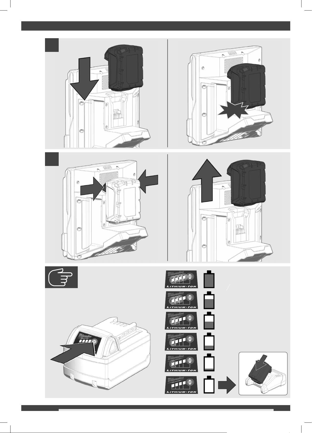
3 Installing and removing battery pack.............................................................................................................. 7
4 Change ONEKEY battery .............................................................................................................................. 8
5 Setup.............................................................................................................................................................. 9
5.1 Power on/off........................................................................................................................................... 9
5.2 First time setup....................................................................................................................................... 9
5.3 Navigating through the settings menu ................................................................................................... 9
5.4 Setting the WIRELESS MONITOR LANGUAGE ................................................................................... 9
5.5 Setting the DATE & TIME..................................................................................................................... 10
5.6 Setting the UNITS of Measure ............................................................................................................. 10
5.7 Setting the SONDE FREQUENCY....................................................................................................... 11
5.8 Setting the COMPANY NAME.............................................................................................................. 11
5.9 VIDEO and IMAGE SETTINGS ........................................................................................................... 12
5.10 CONNECTION SETTINGS.................................................................................................................. 14
5.11 M18™ BATTERY ................................................................................................................................. 16
5.12 Setting the LCD SCREEN SETTINGS................................................................................................. 16
6 Using the WIRELESS MONITOR................................................................................................................. 17
6.1 Using JOBS.......................................................................................................................................... 18
6.2 Creating a Video Recording and Image Capturing .............................................................................. 19
6.3 EXPORT JOB ...................................................................................................................................... 20
6.4 Adjusting the CAMERA LIGHT and IMAGE ENHANCE ...................................................................... 21
6.5 ZOOM & PAN....................................................................................................................................... 21
6.6 Screen ROTATE................................................................................................................................... 22
6.7 LINE TRACE ........................................................................................................................................ 22
6.8 SONDE ................................................................................................................................................ 23
6.9 GALLERY Overview............................................................................................................................. 23
6.10 Playback Highlights.............................................................................................................................. 24
6.11 Playing videos and viewing pictures .................................................................................................... 24
6.12 Rewind and Fast Forward.................................................................................................................... 25
6.13 Trimming Video Files............................................................................................................................ 25
6.14 Recording Audio................................................................................................................................... 26
6.15 Speaker Volume................................................................................................................................... 26
6.16 Delete Files .......................................................................................................................................... 27
6.17 Using LABELS ..................................................................................................................................... 28
7 Factory Reset & Firmware Updates ............................................................................................................ 30
7.1 Factory Reset....................................................................................................................................... 30
7.2 Firmware Updates................................................................................................................................ 30
470 424 - M18SIM - GB Print.indd 2470 424 - M18SIM - GB Print.indd 2 01.07.2020 06:40:4201.07.2020 06:40:42

3ENGLISH
1 GENERAL INFORMATIONS
1.1 Additional Safety and Working Instructions
Do not try to replace the battery pack if the surface of the instrument is wet.
Do not dispose of used battery packs in the household refuse or by burning them. Milwaukee Distributors offer to
retrieve old batteries to protect our environment.
Do not store the battery pack together with metal objects (short circuit risk).
Use only System M 18 chargers for charging System M 18 battery packs. Do not use battery packs from other systems.
Battery acid may leak from damaged batteries under extreme load or extreme temperatures. In case of contact
with battery acid wash it offimmediately with soap and water. In case of eye contact rinse thoroughly for at least
10 minutes and immediately seek medical attention.
Warning! To reduce the risk of fire, personal injury, and product damage due to a short circuit, never immerse
your tool, battery pack or charger in fluid or allow a fluid to flow inside them. Corrosive or conductive fluids, such
as seawater, certain industrial chemicals, and bleach or bleach containing products, etc., Can cause a short
circuit.
This appliance is not intended to be used or cleaned by persons with reduced physical, sensory or mental
capabilities, or lack of experience or knowledge, unless they have been given instructions concerning the safe
use of the appliance by a person legally responsible for their safety. They should be supervised whilst using the
appliance. Children shall not use, clean or play with this appliance, which when not in use should be secured out
of their reach.
Chemical Burn Hazard. This device contains a lithium button/coin cell battery. A new or used battery
can cause severe internal burns and lead to death in as little as 2 hours if swallowed or enters the
body. Always secure the battery cover. If it does not close securely, stop using the device, remove the
batteries, and keep it away from children. If you think batteries may have been swallowed or entered
the body, seek immediate medical attention.
1.2 Technical data
Screen size ..............................................................................................................................................8 "
Screen resolution ......................................................................................................................... 800x600 dpi
Picture resolution ...............................................................................................................................1080 p
Max. zoom.............................................................................................................................................. 4x
Battery voltage .......................................................................................................................................18 V
Weight according EPTA-Procedure 01/2014 (12 Ah)..........................................................................3.82 kg
Frequency band(s) of Bluetooth................................................................................................2402-2480 MHz
Radio-frequency power .........................................................................................................................1.8 dBm
Bluetooth version ........................................................................................................ 4.0 BT signal mode
Recommended ambient operating temperature....................................................................... -18 …. +50 °C
Recommended battery Type ..................................................................................... M18B….; M18HB….
Recommended charger Type.............................................. M12-18C, M12-18AC, M12-18FC, M1418C6
1.3 Specified conditions of use
The wireless monitor allows for viewing the raw video from the camera head, recording videos and capturing
picture images and playback functions of video and picture files. During the recording of videos, audio comments
can be captured through the internal microphone, and text comments can be added via the labels option. These
text comments will appear in the recorded video and will show in the pictures along with the system time, system
date and distance of deployed push cable.
Do not use this product in any other way as stated for normal use.
470 424 - M18SIM - GB Print.indd 3470 424 - M18SIM - GB Print.indd 3 01.07.2020 06:40:4201.07.2020 06:40:42

4ENGLISH
1.4 Radio Frequency Interface Requirements - Related to European installation
Note: This equipment has been tested and found to comply with the limits for a EN 300 440 v2.1.1 receiver
Category 3.
These limits are designed to provide reasonable protection against harmful interference in a residential
installation.
This equipment is sensitive to other equipment that intentionally generates, radio frequency energy in the 2402-
2480MHz that may conduce to the instability to use the Remote Control on it. However there is no guarantee that
interference will not occur in a particular installation. If this equipment suffer from the harmful interference from
another radio device to radio this can be determined by turning the respective equipment offand on, the user is
encouraged to try to correct the interference by one or more of the following measures:
- Turn offthe disturbance equipment
- Increase the separation between the disturbance equipment
- Consult the dealer or an experienced radio technician for help
1.5 EC-declaration of conformity
Hereby, Techtronic Industries GmbH declares that the radio equipment type M18SIM is in compliance with
Directive 2014/53/EU. The full text of the EU declaration of conformity is available at the following internet
address: http://services.milwaukeetool.eu.
1.6 One-key™
To learn more about the ONE-KEY functionality for this tool, please reference the Quick Start guide included with
this product or go to www.milwaukeetool.com/one-key. To download the ONE-KEY app, visit the App Store or
Google Play from your smart device.
Also, when the product experiences ESD, the Bluetooth communication will be disconnected. It needs to be reset
manually to recover.
We considered the results to be within our minimum acceptable performance level according to EN 55014-2:2015
/ EN 301489-1 V2.1.1 / EN 301489-17 V3.1.1.
One-key™ indicator
Solid Blue Wireless mode is active and ready to be configured via the
ONE-KEY™ app.
Blinking Blue Tool is actively communicating with the ONE-KEY™ app.
Blinking Red Tool is in security lockout and can be unlocked by the
owner via the ONE-KEY™ app.
1.7 Batteries
Battery packs which have not been used for some time should be recharged before use.
Temperatures in excess of 50°C (122°F) reduce the performance of the battery pack. Avoid extended exposure to
heat or sunshine (risk of overheating).
The contacts of chargers and battery packs must be kept clean.
For an optimum life-time, the battery packs have to be fully charged, after used.
To obtain the longest possible battery life remove the battery pack from the charger once it is fully charged.
For battery pack storage longer than 30 days:
Store the battery pack where the temperature is below 27°C and away from moisture
Store the battery packs in a 30% - 50% charged condition
Every six months of storage, charge the pack as normal.
1.8 Transporting lithium batteries
Lithium-ion batteries are subject to the Dangerous Goods Legislation requirements.
Transportation of those batteries has to be done in accordance with local, national and international provisions
and regulations.
• The user can transport the batteries by road without further requirements.
470 424 - M18SIM - GB Print.indd 4470 424 - M18SIM - GB Print.indd 4 01.07.2020 06:40:4201.07.2020 06:40:42

5ENGLISH
• Commercial transport of Lithium-Ion batteries by third parties is subject to Dangerous Goods regulations.
Transport preparation and transport are exclusively to be carried out by appropriately trained persons and the
process has to be accompanied by corresponding experts.
When transporting batteries:
• Ensure that battery contact terminals are protected and insulated to prevent short circuit.
• Ensure that battery pack is secured against movement within packaging.
• Do not transport batteries that are cracked or leak.
Check with forwarding company for further advice
1.9 Maintenance
Use only Milwaukee accessories and spare parts. Should components need to be replaced which have not been
described, please contact one of our Milwaukee service agents (see our list of guarantee/service addresses).
If needed, an exploded view of the tool can be ordered. Please state the machine type printed as well as the
six-digit No. on the label and order the drawing at your local service agents or directly at: Techtronic Industries
GmbH, Max-Eyth-Straße 10, 71364 Winnenden, Germany.
1.10 Symbols
CAUTION! WARNING! DANGER!
Remove the battery pack before starting any work on
the machine.
Please read the instructions carefully before starting
the machine.
Do not swallow the coin cell battery!
Do not dispose electric tools, batteries/rechargeable
batteries together with household waste material.
Electric tools and batteries that have reached the end
of their life must be collected separately and returned
to an environmentally compatible recycling facility.
Check with your local authority or retailer for
recycling advice and collection point.
VVolts
Direct current
European Conformity Mark
Ukraine Conformity Mark
EurAsian Conformity Mark
470 424 - M18SIM - GB Print.indd 5470 424 - M18SIM - GB Print.indd 5 01.07.2020 06:40:4201.07.2020 06:40:42

6ENGLISH
2 OVERVIEW
1
2
3
4
5
7
6
8
9
12
10
13
11
14
15
1. Sunshield
2. Internal microphone
3. LCD
4. Distance reset button
5. Power button
6. Back button
7. Microphone button
8. Navigation dial
9. Record video button
10. ONEKEY LED
11. Picture capture button
12. USB-C port
13. USB-A port
14. M18™ BATTERY mounting area
15. ONEKEY battery compartment
470 424 - M18SIM - GB Print.indd 6470 424 - M18SIM - GB Print.indd 6 01.07.2020 06:40:4201.07.2020 06:40:42

7ENGLISH
3 INSTALLING AND REMOVING BATTERY PACK
1
click
2
78-100 %
55-77 %
33-54 %
10-32 %
< 10 %
470 424 - M18SIM - GB Print.indd 7470 424 - M18SIM - GB Print.indd 7 01.07.2020 06:40:4301.07.2020 06:40:43

8ENGLISH
4 CHANGE ONEKEY BATTERY
1
2
3
470 424 - M18SIM - GB Print.indd 8470 424 - M18SIM - GB Print.indd 8 01.07.2020 06:40:4501.07.2020 06:40:45

9ENGLISH
5 SETUP
This section of the manual covers setting up the features and options of the WIRELESS MONITOR. Mounting the
WIRELESS MONITOR to the PIPELINE INSPECTION REEL is covered in section 3.5 of the PIPELINE
INSPECTION REEL manual.
5.1 Power on/off
Press the POWER button to power on the WIRELESS MONITOR.
The buttons and navigation dial will illuminate, showing that the power is on.
The WIRELESS MONITOR icon will appear in the status bar of the LCD along with the battery state.
Press the POWER button for 2 seconds to power offthe WIRELESS MONITOR.
5.2 First time setup
All the settings are saved into the WIRELESS MONITOR's memory and will remain there until changed. Note that
the settings will be lost if the unit is reset to factory defaults or by formatting the CONTROL HUB INTERNAL
DRIVE. The PIPELINE INSPECTION REEL with camera does not need to be connected to the WIRELESS
MONITOR for the first-time setup.
These initial WIRELESS MONITOR settings will set the UNITS of distance measurement, DATE & TIME formats,
SONDE frequencies, VIDEO quality, IMAGE quality, CONNECTION SETTINGS and LANGUAGE.
These settings can also be performed through a tablet running the
MILWAUKEE® PIPELINE INSPECTION APP
.
5.3 Navigating through the settings menu
Navigation dial - Turn the navigation dial clockwise or counter-clockwise to move through the menus.
While rotating the navigation dial, the position/menu items will be highlighted by the red cursor line.
Press the navigation dial to select and accept the setup menu options.
Back button - Pressing the Back button while in any menu or sub-menu will take the screen back to
the previous menu. Press the Back Button repeatedly to return to the main viewing screen.
5.4 Setting the WIRELESS MONITOR LANGUAGE
It is recommended to set your LANGUAGE first so that the other menus can be easily read and understood.
1. Go to SETTINGS LANGUAGE.
2. Select the desired LANGUAGE.
3. Accept the on-screen message
The system will reboot and start in the language selected.
SETTINGS
MANAGE JOBS
2019/05/10 6 FILES
DATE & TIME
UNITS
FACTORY RESET
ABOUT
LANGUAGE
SYSTEM UPDATE
Feet
English
SCREEN SETTINGS
SERVICE & SUPPORT
SETTINGS
The control modules settings have been
changed. These changes will take effect
only after the control module has been
restarted.
CANCEL OK
470 424 - M18SIM - GB Print.indd 9470 424 - M18SIM - GB Print.indd 9 01.07.2020 06:40:4601.07.2020 06:40:46

10ENGLISH
5.5 Setting the DATE & TIME
The system offers DATE FORMATs of MM/DD/YYYY, DD/MM/YYYY and YYYY/MM/DD with 12-Hour or 24-Hour
TIME FORMATs.
1. Go to SETTINGS DATE & TIME.
2. Select the desired DATE FORMAT and TIME FORMAT.
3. Set the DATE and TIME values.
4. When finished setting Date & TIME, press the SAVE key.
The DATE & TIME are now set, and you will be returned to the SETTINGS menu.
If using a tablet running the
MILWAUKEE® PIPELINE INSPECTION APP
, the DATE & TIME are taken from the tablet.
5.6 Setting the UNITS of Measure
1. Go to SETTINGS UNITS.
2. Choose Feet or Meter.
The UNITS of measures are now set, and you will be returned to the SETTINGS menu.
SETTINGS
DATE FORMAT
TIME FORMAT
DATE SET
TIME SET
YYYY/MM/DD
24 HOUR
2019 /10 /23
16 :04 :35
SAVE
SETTINGS
2019/05/10 6 FILES
DATE & TIME
UNITS
Feet
FACTORY RESET
ABOUT
SYSTEM UPDATE
LANGUAGE
English
SCREEN SETTINGS
SERVICE & SUPPORT
SETTINGS
Feet
Meter
470 424 - M18SIM - GB Print.indd 10470 424 - M18SIM - GB Print.indd 10 01.07.2020 06:40:4601.07.2020 06:40:46

11ENGLISH
5.7 Setting the SONDE FREQUENCY
1. Go to SETTINGS SONDE FREQUENCY.
2. Select the desired sonde frequency of 512Hz, 640Hz or 33kHz.
The sonde frequency is now selected and you will be returned to the SETTINGS menu.
5.8 Setting the COMPANY NAME
This setting saves a COMPANY NAME in the system's memory. The COMPANY NAME will splash on the video
recordings start for 5 seconds and appear in all JPEG images.
1. Go to SETTINGS COMPANY NAME.
2. Use the navigation dial to navigate the on-screen keyboard pressing the navigation dial to accept each
keyboard character.
3. When finished with the COMPANY NAME, press the ENTER key.
4. Select SAVE or
CANCEL
to continue.
SETTINGS
512Hz
640Hz
33kHz
SETTINGS
MANAGE JOBS
2019/05/10 6 FILES
MANAGE JOBS
SONDE FREQUENCY
640Hz
IMAGE SETTINGS
1920x1080
CONNECTION SETTINGS
MTCAM_02938B284
CAMERA SETTINGS
LABEL SETTINGS
FORMAT DISK
VIDEO SETTINGS
1080P 30FPS
COMPANY NAME
SETTINGS
ABCDEFGH I J K LMNOPQRSTUV
W
XYZ
SPACE
1234567890 .,-?!
DELETE
MILWAUKEE
ENTER
470 424 - M18SIM - GB Print.indd 11470 424 - M18SIM - GB Print.indd 11 01.07.2020 06:40:4601.07.2020 06:40:46

12ENGLISH
5.9 VIDEO and IMAGE SETTINGS
VIDEO SETTINGS
This setting allows for the selection of the video resolution. The video resolution will affect the video quality, which
in turn affects the size of the video file. The choices for resolution and frames per second (FPS) are:
VIDEO SETTING choices
- 1080p with 30 frames per second or 15 frames per second,
- 720p with 30 frames per second or 15 frames per second,
- 480p with 30 frames per second or 15 frames per second
1. Go to SETTINGS VIDEO SETTINGS.
2. Choose 1080p, 720p or 480p.
3. After a resolution of 1080p, 720p or 480p has been selected the next screen will require a selection of frames
per second.
Choose 30FPS or 15FPS.
4. After the frames per second choice is selected, the system will return to the SETTINGS menu.
SETTINGS
MANAGE JOBS
2019/05/10 6 FILES
MANAGE JOBS
SONDE FREQUENCY
640Hz
IMAGE SETTINGS
1920x1080
CONNECTION SETTINGS
MTCAM_02938B284
CAMERA SETTINGS
LABEL SETTINGS
FORMAT DISK
MILWAUKEE
VIDEO SETTINGS
1080P 30FPS
COMPANY NAME
SETTINGS
1080p
720p
480p
SETTINGS
30FPS
15FPS
470 424 - M18SIM - GB Print.indd 12470 424 - M18SIM - GB Print.indd 12 01.07.2020 06:40:4701.07.2020 06:40:47

13ENGLISH
IMAGE SETTINGS
This setting allows for the choice selection of the picture IMAGE dimensions. These dimensions will affect the
picture quality, which in turn affects the size of the picture file.
Image setting choices - 1920 x 1080, 1280 x 720 or 640 x 480
1. Go to SETTINGS IMAGE SETTINGS.
2. Choose 1920x1080, 1280x720 or 640x480.
3. After the IMAGE setting choice is selected, the system will return to the SETTINGS menu.
SETTINGS
MANAGE JOBS
2019/05/10 6 FILES
MANAGE JOBS
SONDE FREQUENCY
640Hz
IMAGE SETTINGS
1920x1080
CONNECTION SETTINGS
MTCAM_02938B284
CAMERA SETTINGS
LABEL SETTINGS
FORMAT DISK
MILWAUKEE
VIDEO SETTINGS
1080P 30FPS
COMPANY NAME
SETTINGS
1920x1080
1280x720
640x480
470 424 - M18SIM - GB Print.indd 13470 424 - M18SIM - GB Print.indd 13 01.07.2020 06:40:4701.07.2020 06:40:47

14ENGLISH
5.10 CONNECTION SETTINGS
The default connection method for the WIRELESS MONITOR and CONTROL HUB is via WI-FI. The wireless
range between the two units is 150 m. If an active CONTROL HUB is within the 150 m range, it will show here in
the Control Hub List. As a backup, the WIRELESS MONITOR and CONTROL HUB can be connected by using
a USB-C cable.
First-time WIRELESS MONITOR Paring
• If only one CONTROL HUB is in range, the WIRELESS MONITOR will automatically force pair with it without
any user interaction.
• If there is more than one CONTROL HUB in range, the Control Hub List will appear on the WIRELESS
MONITOR or
MILWAUKEE® PIPELINE INSPECTION APP
so the user can choose the desired CONTROL HUB.
SETTINGS
Control Hub List
MTCAM_02938B284
MTCAM_029384BEA
MTCAM_02938ED7A
MTCAM_029383A7E
A C
D
B
AList of nearby CONTROL HUBs with active WI-FI
BBattery Capacity - Both M18™ BATTERY icons have four segments in the icon.
Each segment represents 25% of the battery's power capacity.
A low battery warning will appear when the capacity reaches 10%
CStatus – checkmark indicates as connected
DSignal strength of nearby CONTROL HUBs with active WI-FI
Cable Connected icon – Shows the WIRELESS MONITOR and CONTROL HUB are connected by a USB-C
cable.
CONTROL HUB connection status and wireless signal strength. This icon appears when the CONTROL
HUB is connected to the WIRELESS MONITOR by WI-FI.
PIPELINE INSPECTION REEL icon – appears when the WIRELESS MONITOR and CONTROL HUB are
connected by WI-FI or USB-C cable.
WIRELESS MONITOR icon – appears when the WIRELESS MONITOR and CONTROL HUB are connected
by WI-FI or USB-C cable.
M18™ BATTERY Status icon – two battery icons are shown separated by the WIRELESS
MONITOR icon. The battery icon to the left of the monitor icon represents the CONTROL HUB.
The battery icon to the right of the monitor icon represents the WIRELESS MONITOR.
1. Go to SETTINGS CONNECTION SETTINGS
SETTINGS
MANAGE JOBS
2019/05/10 6 FILES
MANAGE JOBS
SONDE FREQUENCY
640Hz
IMAGE SETTINGS
1920x1080
CONNECTION SETTINGS
MTCAM_02938B284
CAMERA SETTINGS
LABEL SETTINGS
FORMAT DISK
MILWAUKEE
VIDEO SETTINGS
1080P 30FPS
COMPANY NAME
470 424 - M18SIM - GB Print.indd 14470 424 - M18SIM - GB Print.indd 14 01.07.2020 06:40:4701.07.2020 06:40:47

15ENGLISH
2. Choose the desired available CONTROL HUB.
3. After selecting the CONTROL HUB you will be returned to the main menu. The CONTROL HUB name is
shown in the menu bar under the CONNECTION SETTINGS.
USB-C Cable Connection
The WIRELESS MONITOR can also be powered by the CONTROL HUB battery via the supplied USB-C cable.
This is extremely useful in some emergency situations in case your battery runs low.
1. With the supplied USB-C cable, plug one end into the CONTROL HUB and the other into the WIRELESS
MONITOR.
2. Confirm the USB-C connection by checking the icons in the status bar on the right. When connected by
USB-C cable the WI-FI icon is now replaced by the cable-connect icon.
The WI-FI icon is replaced by the cable-connect icon and the WIRELESS MONITOR battery shows as empty.
SETTINGS
Control Hub List
MTCAM_02938B284
MTCAM_029384BEA
MTCAM_02938ED7A
MTCAM_029383A7E
SETTINGS
MANAGE JOBS
2019/05/10 6 FILES
MANAGE JOBS
SONDE FREQUENCY
640Hz
IMAGE SETTINGS
1920x1080
CONNECTION SETTINGS
MTCAM_02938B284
CAMERA SETTINGS
LABEL SETTINGS
FORMAT DISK
MILWAUKEE
VIDEO SETTINGS
1080P 30FPS
COMPANY NAME
CAMERA LIGHT
3.2M2020/04/17 11:30:57 AM
470 424 - M18SIM - GB Print.indd 15470 424 - M18SIM - GB Print.indd 15 01.07.2020 06:40:4701.07.2020 06:40:47

16ENGLISH
5.11 M18™ BATTERY
Both the WIRELESS MONITOR and CONTROL HUB are powered by an M18™ BATTERY. The battery condition
of both is always shown in the status bar on the WIRELESS MONITOR screen.
Recharge only with the charger specified for the battery. For specific charging instructions,
read the operator's manual supplied with your charger and battery.
The icon to the left of the WIRELESS MONITOR icon represents the battery status of the CONTROL HUB while
the icon to the right represents the WIRELESS MONITOR.
The CONTROL HUB is powered by its M18™ BATTERY which is hot-swappable. If the battery is removed from a
running CONTROL HUB, the below message will appear warning that the CONTROL HUB is operating on the
internal backup battery for a period of nine minutes. During these nine minutes a charged M18™ BATTERY must
be installed, or a USB-C cable must be attached between the WIRELESS MONITOR and CONTROL HUB. The
USB-C cable will now power the CONTROL HUB temporally.
Typical battery life:
WIRELESS MONITOR: Nine hours on a fully charged battery
CONTROL HUB: Nine hours on a fully charged battery
5.12 Setting the LCD SCREEN SETTINGS
This setting adjusts the WIRELESS MONITOR LCD screen settings.
1. Go to SETTINGS SCREEN SETTINGS.
2. Use the navigation dial to navigate through the menu choices, press the navigation dial to select one.
3. Turn the navigation dial left and right to adjust the setting, press the navigation dial to accept it.
4. Scroll to the bottom of the sub-menu and press the navigation dial on OK to accept the changes.
CAMERA LIGHT
9.3FT2019/10/23 01:47:57 AM
2020/04/17 11:30:45 AM 3.2M
CAMERA LIGHT
2020/04/17 11:30:45 AM 3.2M
2019_10_23_SCREEN
Replace Control Hub battery or
Connect Cable to Wireless Monitor
immediately
Time remaining : 08:51
Hue
Brightness
Contrast
Saturation
Backlight
50
50
50
50
8
Cancel OK
470 424 - M18SIM - GB Print.indd 16470 424 - M18SIM - GB Print.indd 16 01.07.2020 06:40:4901.07.2020 06:40:49

17ENGLISH
6 USING THE WIRELESS MONITOR
Many of these instructions also apply to the Milwaukee® Pipeline Inspection App. The Milwaukee® Pipeline
Inspection App is available for download from the Apple App Store or at Google Play.
CAMERA LIGHT
2020/04/17 11:30:45 AM 3.2M
2020_04_17_JOB1
1 2 3 4 5 76 8 9
11 1210 1413 15 16 17 18 19
1 DATE and TIME stamp: displayed from the system and will appear in all recorded videos image files.
2 Status bar: shows the running options, menu location, connection status and battery status of both the
CONTROL HUB and WIRELESS MONITOR. The status bar is always shown regardless of what mode or
option is being used.
3 Menu location
4 WI-FI status
5 CONTROL HUB connection status icon
6 CONTROL HUB battery status
7 WIRELESS MONITOR connection status icon
8 WIRELESS MONITOR battery status
9 Distance out count
10 Main viewing area: shows the raw video from the camera or videos being played back.
11 Active JOB description
12 CAMERA LIGHT: of the cameras LED's are controlled here
13 ZOOM & PAN: allows for 4 x zooming with vertical and horizontal panning of the video feed.
14 LABELS
15 Screen ROTATE
16 LINE TRACE
17 SONDE
18 GALLERY
19 SETTINGS menu
470 424 - M18SIM - GB Print.indd 17470 424 - M18SIM - GB Print.indd 17 01.07.2020 06:40:5201.07.2020 06:40:52

18ENGLISH
6.1 Using JOBS
Before creating a video or image file, you can tell the system where to store the files. This is known as creating a
NEW JOB or CONTINUE EXISTING JOB. Creating a NEW JOB will setup a container (folder) for both video and
image files to be stored in. CONTINUE EXISTING JOB will route the recordings to a JOB folder that already
exists.
The system will automatically ask which JOB to use in certain situations.
- Whenever the system clock changes to a new day (after 11:59PM).
- Whenever the CONTROL HUB is restarted (turned offand on again).
When the Record button is pressed under the above situations, the SELECT JOB List will appear with options of:
NEW JOB WITH DATE AND TIME, NEW JOB WITH NAME or EXISTING JOB. From this point on the same JOB
will be used until changed.
1. Go to SETTINGS MANAGE JOBS.
The MANAGE JOBS sub-menu has five menu options.
NEW JOB WITH DATE AND TIME - Creates a NEW JOB with the systems date and time as the prefix for all
files in this folder.
NEW JOB WITH NAME - Creates a NEW JOB with the text title entered via the on-screen keyboard.
CONTINUE EXISTING JOB – Sends the new files to an EXISTING JOB previously created.
EXPORT JOB – Copies the JOB from the CONTROL HUB INTERNAL DRIVE to a CONTROL HUB THUMB
DRIVE.
DELETE JOB – Deletes the JOB from the CONTROL HUB INTERNAL DRIVE.
2. Choose the desired sub-menu.
The changes will be saved into memory, and the system will return to the main viewing screen.
Creating a NEW JOB
1. Go to NEW JOB WITH DATE AND TIME or NEW JOB WITH NAME.
If NEW JOB WITH DATE AND TIME is selected a JOB folder with the system current date and time will be
created and named YYYY_MM_DD_HH_MM_SS.
If a NEW JOB WITH NAME is selected, the next screen will be the on-screen keyboard.
2. Use the navigation dial to enter the name.
3. When finished save the name.
When a NEW JOB WITH NAME is selected a JOB folder with the system current date and time will be used
as a prefix. The folder created and named YYYY_MM_DD_NEW JOB NAME.
SETTINGS
NEW JOB WITH DATE AND TIME
NEW JOB WITH NAME
DELETE JOB
CONTINUE EXISTING JOB
EXPORT JOB
ABCDEFGH I J K LMNOPQRSTUV
W
XYZ
SPACE
1234567890 .,-?!
DELETE
MT2019_A
ENTER
MT2019_A
CANCEL SAVE
470 424 - M18SIM - GB Print.indd 18470 424 - M18SIM - GB Print.indd 18 01.07.2020 06:40:5401.07.2020 06:40:54

19ENGLISH
6.2 Creating a Video Recording and Image Capturing
By default, all videos and images recorded are saved to the CONTROL HUB INTERNAL DRIVE. If a thumb drive
is plugged into the CONTROL HUB, all videos and pictures can be saved to both the CONTROL HUB INTERNAL
DRIVE and CONTROL HUB THUMB DRIVE.
Filenames – the file names are automatically created by the system and consist of the year, month, day, time
created, and or JOB name. This will vary depending on the JOB type selected.
If selecting NEW JOB WITH DATE AND TIME, the filename will look like this:
2019_10_01_12_50_10_2
2019 = Year, _10 = Month, _01 = Day, _12 = Hour, _50 = Minutes, _10 = Seconds and _2 = second file created.
If selecting NEW JOB WITH NAME, the filename will look like this:
2019_10_01_JOBNAME_3
2019 = Year, _10 = Month, _01 = Day, _JOBNAME and_3 = third file created.
If a file were saved as a Highlight video, the filename would be followed by "_h".
1. Press the Record button to start the recording. If this is the first recording of the day or if the WIRELESS
MONITOR or CONTROL HUB was restarted, when the record button is pressed the SELECT JOB dialog box
will appear to route the recording record to the appropriate JOB folder.
2. Choose the desired option and press the navigation dial.
3. After the JOB option has been selected, a flashing recording icon will appear in the upper left corner of the
status bar with the video recording length in minutes and seconds.
Images can be captured while recording or viewing raw video from the camera. The image will be saved in
the same JOB folder as the video.
4. Press the PICTURE button to capture an image. The screen will flash red for a moment confirming that
the image was captured.
At the end of the session, press the RECORD button again to end and save the video file.
2020/04/17 11:30:45 AM 3.2M
SETTINGS
SELECT JOB
NEW JOB WITH DATE AND TIME
NEW JOB WITH NAME
EXISTING JOB
CANCEL
No job selected
2020/04/17 11:30:45 AM 3.2M
2019_10_23_JOB1
SETTINGS
00:05
470 424 - M18SIM - GB Print.indd 19470 424 - M18SIM - GB Print.indd 19 01.07.2020 06:40:5401.07.2020 06:40:54

20ENGLISH
6.3 EXPORT JOB
The EXPORT JOB allows for the copying of files from the CONTROL HUB INTERNAL DRIVE to the CONTROL
HUB THUMB DRIVE.
From within the GALLERY individual files can be exported one at a time.
From the MANAGE JOBS option, under SETTINGS entire folders of JOBS can be EXPORTED in one
session.
EXPORT JOB from the GALLERY
1. Go to GALLERY
2. Select the desired video or image.
3. Go to EXPORT
4. Choose CONTROL HUB THUMB DRIVE.
The progress indicator will appear showing the status.
5. Wait for the progress indicator to run until completed.
EXPORT JOB from within the SETTINGS menu
1. Go to SETTINGS MANAGE JOBS EXPORT JOB.
2. Select the JOB and choose CONTROL HUB THUMB DRIVE.
The progress indicator will show the status.
3. Wait for the progress indicator to run until completed.
2020/17/04 11:30:45 AM 3.3M
2019_10_23_SCREEN
EXPORT
EXIT
PLAYBACK
00:00 / 00:40
EXPORT
CONTROL HUB THUMB DRIVE
3.942GB/29.817GB
Saving “PROJECTNAME”.
CANCEL
EXIT
SETTINGS
CONTROL HUB THUMB DRIVE
3.942GB/29.817GB
Saving “PROJECTNAME”.
CANCEL
470 424 - M18SIM - GB Print.indd 20470 424 - M18SIM - GB Print.indd 20 01.07.2020 06:40:5701.07.2020 06:40:57
This manual suits for next models
1
Table of contents
Other Milwaukee Monitor manuals