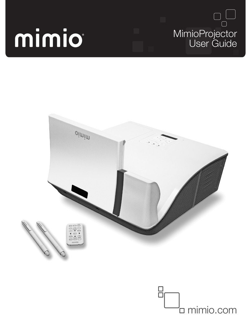
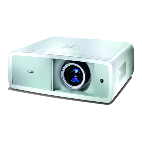
Mimio MimioProjector User manual

SERVICE MANUAL
TSE: Chris Check: Amy Approved: Alick
Date Revise Version Description
2013.03.06 V1.0 Initial Issue
MimioProjector

IMimioProjector Service Manual
Preface
This manual is applied to MimioProjector. The manual gives you a brief description of basic
technical information to help in service and maintain the product.
This manual is for technicians and people who have an electronic background. Please
send the product back to the distributor for repairing and do not attempt to do anything that
is complex or is not mentioned in the troubleshooting.
Notice: The information found in this manual is subject to change without prior notice.
Any subsequent changes made to the data herein will be incorporated in
future edition.
MimioProjector Service Manual
Copyright Mar. 2013
All Rights Reserved
Manual Version 1.0

II
MimioProjector Service Manual
Table of Content
Chapter 1 Introduction
Highlight 1-1
Compatible Mode 1-3
Chapter 2 Disassembly Process
Equipment Needed & Product Overview 2-1
Disassemble Lamp module and mesh inlet 2-2
Disassemble Top cover module 2-3
Disassemble Main board 2-8
Disassemble IO cover and bottom shielding 2-12
Disassemble lamp driver and LVPS Module 2-13
Disassemble speaker and AC inlet 2-16
Disassemble C/W Module 2-18
Disassemble Engine Module 2-19
Disassemble SYS FAN and Blower 2-22
Disassemble Bottom Cover Module 2-24
Re-write Lamp Usage Hour 2-26
Repair Action 2-27
Chapter 3 Troubleshooting
LED Lighting Message 3-1
Main Procedure 3-2
No power troubleshooting 3-3
Power troubleshooting 3-4
Image troubleshooting 3-7

III MimioProjector Service Manual
Remote control troubleshooting 3-11
Pin Assignment 3-12
Electronic Function Block Diagram 3-14
Chapter 4 Function Test & Alignment Procedure
Test Equipment Needed 4-1
Test Condition 4-1
Test Procedure 4-2
VGA Port Test 4-3
Audio Test 4-7
S-Video port Test 4-7
HDMI port Test 4-7
3D Test 4-8
Video port Test 4-8
Run In Test 4-9
Test Inspection procedure 4-10
ADC Calibration 4-11
Waveform Download 4-12
Fan Calibration 4-13
Chapter 5 Firmware Upgrade
Section 1: Scalar Firmware Upgrade 5-1
Section 2: PIC Firmware Upgrade Procedure 5-6

IV
MimioProjector Service Manual
Chapter 6 EDID Upgrade
EDID Upgrade 6-1
Appendix A
Exploded Image I
Appendix B
Serial Number System Denition I
PCBA Code Denition II

1-1MimioProjector Service Manual
Chapter 1: Introduction
1. Introduction
1-1 Highlight
No Item Description
1 Dimensions • 357 (W) x 367 (D) x 135(H) mm (excluding foot)
2 Power Supply • Universal AC 100 – 240 V ,50-60 Hz
3Power Consumption
• Normal mode: 300 W+/-10%@110VAC
• ECO mode: 240 W+/-10%@110VAC
• Standby< 0.5W@ VGA out and RS232, LAN/Wireless
module
disable
4 Native resolution • Native Resolution: 1280 x 800(WXGA)
5 Projection lens • Fixed Lens(YM105)
6 Throw Distance • WXGA: 597mm –731mm±10mm, 654mm±10mm @87.2”
(TR=0.35)
7 Throw Ratio • WXGA: 0.35
8 Brightness • WXGA: typical: 2400 lumens, Minimum: 2080 lumens
9 Contrast ratio
• Typical 2000 : 1 (Native) (White @ 100% lamp power/
Black @ 100% lamp power)
• Typical 8000 : 1 (High Contrast mode) (White @ 100%
lamp power/Black @ 30% lamp power)
10 Color Wheel • 44mm diameter, 6 segments, R78 Y44 G81 C34 W55
B68_URD20VA
11 DMD chip • TI DMD 0.65” WXGA 2xLVDS S450
12 Native resolution • WXGA: 80.2”~96.6”, Optimization on 87.2”.(Diagonal)
13 System controller • TI DDP4421
14 Lamp Type • 240 Watt OSRAM E20.8 Lamp
15 Lamp Life • Normal mode: 3500 hours min, 50% survival rate
• Eco mode: 5000 hours min, 50% survival rate
16 Long cable supportable
• VGA cable, 10M (R/G/B with impedance:75Ω±10%,
H/V with impedance:50Ω±10%)
• HDMI cable: 10M
17 Uniformity • 80%(Typical)
• 65% (min.)

1-2 MimioProjector Service Manual
Chapter 1: Introduction
No Item Description
18 Video Compatibility
• NTSC: M (3.58MHz), 4.43 MHz• Vsync Frequency
50 ~ 120 Hz
• PAL: B, D, G, H, I, M, N
• SECAM: B, D, G, K, K1, L
• HDTV: 720p, 1080i, 1080p
• EDTV: 480p, 576p
• SDTV: 480i, 576i
19 Altitude
• Operating: 5°C -- 40°C (0~2500ft)
5°C -- 35°C (2500~5000ft)
5°C -- 30°C (5000~10000ft)
20 Operation temperature • 5 ~ 40°C

1-3
MimioProjector Service Manual
Chapter 1: Introduction
Mode Resolution V-Sync[Hz] H-Sync(KHz)
VGA
640x480 60 31.50
640x480 67 35.0
640x480 72 37.90
640x480 75 37.5
640x480 85 43.3
640x480 120 61.9
IBM 720x400 70 31.5
SVGA
800 x 600 56 35.10
800 x 600 60 37.90
800 x 600 72 48.10
800 x 600 75 46.90
800 x 600 85 53.70
800 x 600 120 77.4
Apple, Mac II 832 x 624 75 49.1
XGA
1024 x 768 60 48.40
1024 x 768 70 56.50
1024 x 768 75 60.00
1024 x 768 85 68.70
1024 x 768 120 99
Apple, Mac II 1152 x 864 75 68.7
SXGA
1280 x 1024 60 64
1280 x 1024 72 77
1280 x 1024 75 80
Quad VGA 1280x960 60 60
1280x960 75 75
SXGA+ 1400 x 1050 60 65.3
UXGA 1600 x 1200 60 75.00
1-2 Compatible Mode
VGA Analog
(1) PC Signal

1-4 MimioProjector Service Manual
Chapter 1: Introduction
(2) Extended Wide Timing
Mode Resolution V-Sync[Hz] H-Sync(KHz)
WXGA
1280x720 60 44.8
1280x800 60 49.6
1366x768 60 47.7
1440x900 60 59.9
WSXGA+ 1680x1050 60 65.3
(3) Component Signal
Mode Resolution V-Sync[Hz] H-Sync(KHz)
480i 720x480(1440x480) 59.94(29.97) 15.7
576i 720x576(1440x576) 50(25) 15.6
480p 720x480 59.94 31.5
576p 720x576 50 31.3
720p 1280x720 60 45.0
720p 1280x720 50 37.5
1080i 1920x1080 60(30) 33.8
1080i 1920x1080 50(25) 28.1
1080p 1920x1080 23.98/24 27.0
1080p 1920x1080 60 67.5
1080p 1920x1080 50 56.3
HDMI Digital
(1) PC Signal
Mode Resolution V-Sync[Hz] H-Sync(KHz)
VGA
640x480 60 31.50
640x480 67 35.0
640x480 72 37.90
640x480 75 37.5
640x480 85 43.3
640x480 120 61.9
IBM 720x400 70 31.5
SVGA
800 x 600 56 35.10
800 x 600 60 37.90
800 x 600 72 48.10
800 x 600 75 46.90
800 x 600 85 53.70
800 x 600 120 77.4

1-5
MimioProjector Service Manual
Chapter 1: Introduction
Mode Resolution V-Sync[Hz] H-Sync(KHz)
Apple, Mac II 832 x 624 75 49.1
XGA
1024 x 768 60 48.40
1024 x 768 70 56.50
1024 x 768 75 60.00
1024 x 768 85 68.70
1024 x 768 120 99
Apple, Mac II 1152 x 864 75 68.7
SXGA
1280 x 1024 60 64
1280 x 1024 72 77
1280 x 1024 75 80
Quad VGA 1280x960 60 60
1280x960 75 75
SXGA+ 1400 x 1050 60 65.3
UXGA 1600 x 1200 60 75.00
(2) Extended Wide Timing
Mode Resolution V-Sync[Hz] H-Sync(KHz)
WXGA
1280x720 60 44.8
1280x800 60 49.6
1366x768 60 47.7
1440x900 60 59.9
WSXGA+ 1680x1050 60 65.3
(3) HDMI-Video Signal
Mode Resolution V-Sync[Hz] H-Sync(KHz)
640x480p 640x480 59.94/60 31.5
480i 720x480(1440x480) 59.94(29.97) 15.7
576i 720x576(1440x576) 50(25) 15.6
480p 720x480 59.94 31.5
576p 720x576 50 31.3
720p 1280x720 60 45.0
720p 1280x720 50 37.5
1080i 1920x1080 60(30) 33.8
1080i 1920x1080 50(25) 28.1
1080p 1920x1080 23.98/24 27.0
1080p 1920x1080 60 67.5
1080p 1920x1080 50 56.3
Note:If the compatibility supportive signal is different from user's manual,
please refer to user's manual.

2-1
MimioProjector Service Manual
2. Disassembly Process
Chapter 2: Disassembly Process
2-1 Equipment Needed & Product Overview
1. Projector
2. Hex socket driver 7mm
3. Long Nose Nipper
4. Screw Bit (+) :105
5. Screw Bit (+) :107
6. Screw Bit
(-)
:107
7. Hex socket driver 5 mm
8. + NO.0 Phillips Screwdriver
* Before you start: This process is protective level II. Operators should wear an anti-
static wrist band. Please place the protective cover or protective plastic on the lens
and mirror to prevent scratching.

2-2
Chapter 2: Disassembly Process
2-2 Disassemble Lamp
Module and Mesh Inlet
1. Loosen 2 screws (red circles) on the
Lamp Cover.
2. Separate the Lamp cover and Lamp cover
strap (green squares).
3. Loosen 2 screws (yellow circles) on
the Lamp Module.
4.Slide out the Lamp Module.
LAMP COVER
LAMP MODULE
MimioProjector Service Manual

2-3
MimioProjector Service Manual
Chapter 2: Disassembly Process
5. Remove the two mesh inlet lters.
2-3 Disassemble Top Cover
Module
1. Push (A) part and pull the (B) part of the
corner cover at the same time to remove it.
BACK MESH INLET SIDE MESH INLET

2-4
Chapter 2: Disassembly Process
2. Unscrew 2 screws (red circles).
3. Disassemble the Bottom Cap (green
squares).
4. Unscrew 2 screws (yellow circles).
5. Remove the front mirror cover module.
FRONT MIRROR COVER MODULE
MimioProjector Service Manual

2-5
MimioProjector Service Manual
Chapter 2: Disassembly Process
7. Unscrew 2 screws (green circles)
to remove wireless top cover.
WIRELESS TOP COVER
6. Remove the rear mirror cover.
REAR MIRROR COVER

2-6
Chapter 2: Disassembly Process
MimioProjector Service Manual
8. Uscrew 2 screws (red circles).
9.Unscrew 2 screws (green circles).
10. Unscrew 3 screws (blue circles).
11.Unscrew 3 screws (yellow circles).
12.Unscrew 2 screws (red circles).

2-7
MimioProjector Service Manual
Chapter 2: Disassembly Process
13.Pull upward the Top Cover Module.
14.Unplug 1 connector (blue square),
then remove the top cover module.
15.Tear off the keypad mylar and sponge
(yellow squares). Then unscrew 2 screws
to disassemble the IR camera transform
board.
16. Unplug 1 connector to remove the
IR camera transform board.
17.Unscrew 4 screws (red circles) and
take off keypad board module.
KEYPAD BUTTON
IR CAMERA TRANSFORM BD

2-8
Chapter 2: Disassembly Process
MimioProjector Service Manual
18.Separate the keypad board and FPC
cable.
2-4 Disassemble Main Board
1.Unscrew 11 screws (red circles)
to disassemble the main board shielding.
FPC CABLE KEYPAD BOARD
TOP COVER

2-9
MimioProjector Service Manual
Chapter 2: Disassembly Process
2.Unscrew 6 screws (green circles) .
3. Unscrew 8 screws (blue circles)
and 4 hex screws (yellow circles).
4. Tear off the tape (red squares).

2-10
Chapter 2: Disassembly Process
MimioProjector Service Manual
5. Unplug 11 connectors (yellow squares).
Item Male Connector
on Main Board The key feature Figure
AIR CAMERA TRANS-
FORM BOARD
Composed of Red/White/Black/
Green wire, White connector and
Black wire tube (4 pin)
B FAN3 Composed of Red/White/Black
wire,White connector(3 pin)
C FAN1 Composed of Red/Blue/Black
wire, White connector(3 pin)
D PHOTO SENSOR
Composed of Red/White/Black-
wire, Green connector and Gray
wire tube (3 pin)
E LAMP DRIVER Black wire tube (5 pin)
F LVPS TO M/B Black wire tube (16 pin)
ABCDEFG
I
HJ
Other manuals for MimioProjector
2
Table of contents
Other Mimio Projector manuals
