Minco TT273 User manual

1
MINCO
TT273
2-wire Temperature Transmitter
Installation and Operating Instructions
PRODUCTS, INC.
7300 Commerce Lane / Minneapolis, MN 55432-3177 U.S.A.
Telephone: (763) 571-3121 / FAX: (763) 571-0927
2
Description
Model TT273 is a 2-wire temperature transmitter for RTD (resistance temperature detector) thermometers. The
TemptranTM converts the RTD's signal into a 4 to 20 mA current. The current changes according to the range
marked on the Temptran: 4 mA at the lowest temperature of the range, rising to 20 mA at the top of the range.
The leads that supply power also carry the current signal. Request Minco Application Aid 15 for more
information.
Installation
Locate the Temptran near the RTD, in an area where the ambient temperature stays between -40 and 85 °C (-40
and 185 °F). If calibration will be necessary, set dip-switches before attaching unit to the DIN rail.
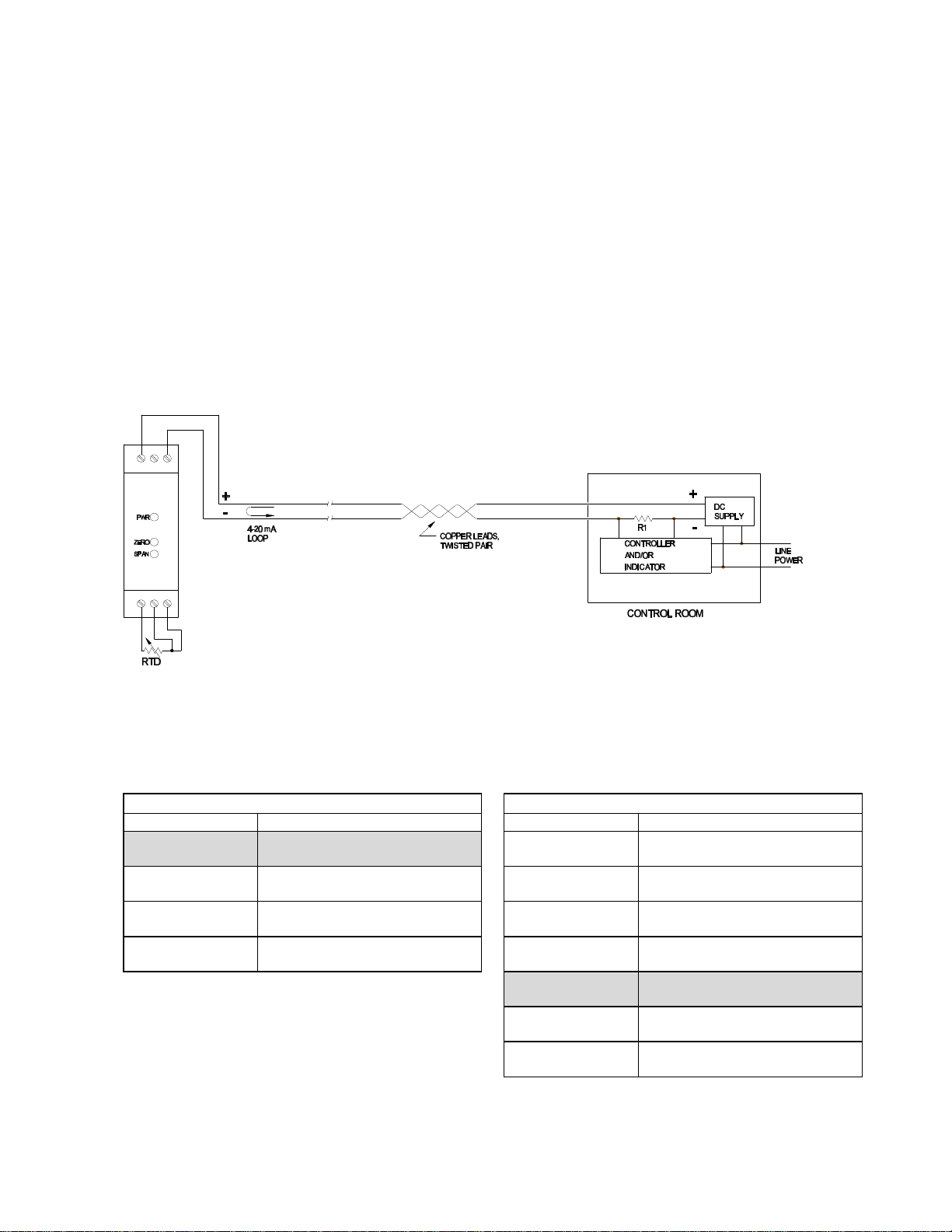
Connect the Temptran as shown below, observing the ±polarity of the current loop. Maximum DC supply
voltage = 45 VDC. The RTD connections for the Temptran in the wiring diagram below must be connected as
shown or the transmitter will not function properly.
Wiring Diagram
Calibration
1. Select desired Zero (4 mA temp.) temperature and Span (20 mA temp. - 4 mA temp.) range from the tables
below. The Zero temperature must be within -50 to 150 °C, and the Span range must be within 50 to 600
°C. For example, for a -25 to 200 °C temperature range, the Zero temperature is -25 °C and the Span
range is (200-(-25)) = 225 °C. According to the tables, switch positions 1 and 8 would be ON.
2. Set dip-switches per values selected from tables.
4. Connect a power supply of 24 VDC, and a digital milliammeter (5-1/2 digit preferred) as shown in figure 1,
or use a loop calibrator instead of the DC supply and milliammeter.
Zero (4 mA) coarse adjust
Switch Position Zero Range / Ohm Setting
1 ON
2,3 OFF -50 to 0 °C (-58 to 32 °F)
80.306 Ωto 100.000 Ω
2 ON
1,3 OFF 0 to 50 °C (32 to 122 °F)
100.000 Ωto 119.397 Ω
3 ON
1,2 OFF 50 to 100 °C (122 to 212 °F)
119.397 Ωto 138.506 Ω
1,2,3 OFF 100 to 150 °C (212 to 302 °F)
135.506 Ωto 157.025 Ω
Span (20 mA - 4 mA) coarse adjust
Switch Position Span Range / Ohm Setting
4 ON
5-9 OFF 50 to 70 °C (90 to 126 °F)
119.397 Ωto 127.075 Ω
5 ON
4,6-9 OFF 70 to 100 °C (126 to 180 °F)
127.075 Ωto 138.506 Ω
6 ON
4,5,7-9 OFF 100 to 140 °C (180 to 252 °F)
138.506 Ωto 153.584 Ω
7 ON
4-6,8,9 ON 140 to 200 °C (252 to 360 °F)
153.584 Ωto 175.856 Ω
8 ON
4-7,9 OFF 200 to 300 °C (360 to 540 °F)
175.856 Ωto 212.052 Ω
9 ON
4-8 OFF 300 to 425 °C (540 to 765 °F)
212.052 Ωto 255.672 Ω
4-9 OFF 425 to 600 °C (765 to 1080 °F)
255.672 Ωto 313.708 Ω

3
5. Connect a resistance decade box with a resolution of at least .01 ohms to the input of the transmitter. If
unsure or concerned about the decade box's accuracy, measure the zero and span resistance settings
using a known-accurate ohmmeter and record decade box settings before connecting decade box to the
transmitter.
6. Set decade box resistance to simulate the 4 mA temperature. For the given example, the decade box
resistance should be set to simulate -25 °C.
7. Adjust ZERO potentiometer on the transmitter until the meter reads 4 mA.
8. Set decade box resistance to simulate the 20 mA temperature. For the given example, the decade box
resistance should be set to simulate 200 °C.
9. Adjust SPAN potentiometer on the transmitter until the meter reads 20 mA.
10. Repeat steps 6 - 9 until no further adjustment is necessary.
Warranty
Items returned within one year from the date of sale, transportation prepaid, which Minco Products, Inc. (The
"Seller") reasonably determines to be faulty by reason of defective materials or faulty workmanship will be
replaced or repaired at the Seller's discretion, free of charge.
This remedy is to be the sole and exclusive remedy available to the buyer in the event of a breach by the Seller.
Items that show evidence of mishandling or misapplication may be returned by the Seller at the customer's
expense.
Furthermore, the Seller is not to be held responsible for consequential damages caused by its product except as
required under Minnesota Statutes, Section 336.1-719 (3).
This warranty is expressly in lieu of any other expressed warranty or implied warranty of merchantability or
fitness for a particular purpose, and of any other obligations or liability on the part of the Seller or its employees
or agents.

4
Specifications
Input: 2-, or 3-wire 100 ohm platinum RTD's.
Output: 4 to 20 mA DC over specified range.
Accuracy: +/- 0.2% of span.
Linearity: +/- 0.2% of span.
Adjustments: Zero: -50 °C to 150 °C
Span: 50 °C to 600 °C
Ambient Temperature:
Operating: -40 to 85 °C ( -40 to 185 °F ).
Storage: -55 to 100 °C ( -67 to 212 °F ).
Ambient Temperature Effects:
+/- 0.01% of span/°F (+/- 0.018% of span/°C).
Warmup Drift: +/- 0.1% of span max., assuming
Vsupply = 24 VDC and Rloop = 250 ohms. Stable
within 15 minutes.
Input/Output Isolation (Optional): 600 VRMS, 1
minute.
Supply Voltage:
Non-Isolated: 10 to 45 volts DC with no load.
Isolated: 13 to 45 volts DC with no load.
Reverse polarity protected.
Voltage effect: +/- 0.001% of span per volt.
Lead Wire Compensation (3-wire RTD): +/- 0.05% of
span per ohm, up to 25 ohms in each leg.
Maximum Load Resistance:The maximum allowable
resistance of the signal-carrying loop is given by this
formula:
Non-Isolated: Rloop max = (Vsupply-10)/.02
amps)
Isolated: Rloop max = (Vsupply-13)/.02
amps)
Maximum Output Current:28 mA.
Connections: Terminal block accepts wires from AWG
22
to AWG 14.
Weight: 4.2 oz. (119 grams).
Model Number Coding:
TT273 PD 1 I (-25/+50) C . . . Sample part number
Temperature Scale: F = Fahrenheit, C = Celsius
Temperature Range: (4 mA temperature / 20 mA temperature)
Input/Output: N= Non-Isolated; I= Isolated to 600 VRMS, 1 minute
Output: 4-20 mA DC.
RTD Element Code: 100 ΩPlatinum at 0 °C
TCR’s: PA = 0.00392, PB = 0.00391, PD = PE = 0.00385
Model Number:TT273, DIN Rail Mount RTD Temptran
Dimensions: All dimensions are in inches (millimeters)
When quality and performance are as important as price, call...
MINCOMINCOPRODUCTS, INC.
7300 Commerce Lane/Minneapolis, Minnesota 55432-3177 U.S.A.
Telephone (763)571-3121 / FAX:(763)571-0927
Copyright 2001, Minco Products, Inc.
Other Minco Transmitter manuals


Popular Transmitter manuals by other brands

KLAY-INSTRUMENTS
KLAY-INSTRUMENTS 2000-VALVE-RANGE Series instruction manual

Detecto
Detecto MZ-4.433 manual

jcm-tech
jcm-tech FREE 15R user manual

Greystone Energy Systems
Greystone Energy Systems AVDT Series installation instructions

Honeywell
Honeywell 5815-1 installation instructions

Scosche
Scosche freqOUT FMTD7 manual


