manuals.online logo
Brands
  1. Home
  2. •
  3. Brands
  4. •
  5. HK Instruments
  6. •
  7. Transmitter
  8. •
  9. HK Instruments Siro-MOD Series User manual

HK Instruments Siro-MOD Series User manual

Copyright HK Instruments 2021 www.hkinstruments. Installaon version 1.0 2021
INSTALLATION
INSTRUCTIONS
Indoor air quality transmitters
Siro-MOD series
• READ THESE INSTRUCTIONS CAREFULLY BEFORE ATTEMPTING
TO INSTALL, OPERATE OR SERVICE THIS DEVICE.
• Failuretoobservesafetyinformaonandcomplywithinstrucons
canresultinPERSONALINJURY,DEATHAND/ORPROPERTY
DAMAGE.
• Toavoidelectricalshockordamagetoequipment,disconnect
powerbeforeinstallingorservicinganduseonlywiringwith
insulaonratedforfulldeviceoperangvoltage.
• Toavoidpotenalreand/orexplosiondonotuseinpotenally
ammableorexplosiveatmospheres.
• Retaintheseinstruconsforfuturereference.
• Thisproduct,wheninstalled,willbepartofanengineeredsystem
whosespecicaonsandperformancecharacteriscsarenot
designedorcontrolledbyHKInstruments.Reviewapplicaons
andnaonalandlocalcodestoassurethattheinstallaonwill
befunconalandsafe.Useonlyexperiencedandknowledgeable
technicianstoinstallthisdevice.
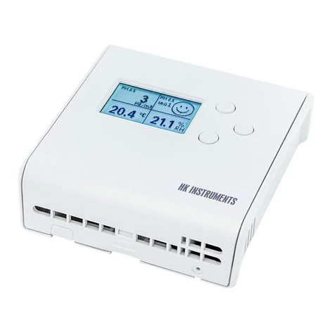
ThankyouforchoosinganHKInstrumentsSiro-MODseriesindoorair
quality transmier. The Siro-MOD series transmiers are intended for
useinbuildingautomaonsystemsintheHVAC/Rindustry.
Siro-MODisanindoorairqualitytransmierwithamoderndesign.The
transmier is available with several oponal air quality sensors. The
modulardevicecanbeequippedwithCO2concentraonandVOC(Vola-
leOrganicCompounds)measurementsoralternavelyPM(Parculate
Maer)measurementandinaddiontemperatureandhumiditymeas-
urements. It oers easy installaon and adjustment, several dierent
modeloponsandvariousoutputsignalsthatarecongurableseparately
foreachmeasurementparameter.
The Siro-MOD series devices are available with user interface that in-
cludesLCDdisplayandbuonsmakingtheconguraonofthedevice
quickandeasy.Anexternalconguraontoolisnecessaryforcommis-
sioning preparaons for Siro-MOD without user interface. Congura-
onisalsopossibleviaModbusnetwork.Siro-MODulizestheindustry
standardNDIRmeasurementprinciplewithself-calibrangABClogicTM
for CO2measurement.
•PMconcentraontomeasuresthesizeandamountofparculates
intheindoorairforexampletoassesstheperformanceofairlters
•temperatureandhumidityinHVAC/Renvironment
SPECIFICATIONS
Performance
Measurement ranges:
CO2:   0–2000ppm/400–2000ppm
 (selectableviajumper)
VOC:   CO₂eq:400–2000ppm
   TVOCppm:0–30.0ppm
   TVOCµg/m3:0–10000µg/m3
 IAQindex:1–5(UBArang)
PM1/PM2.5/PM10: 0–50μg/m³/0–500μg/m³
   (selectableviajumper)
  IAQindex:1-5(WHOrang)
Temperature:  0...50°C
Relavehumidity: 0–100%rH
Accuracy:
CO2:   ±30ppm+3%ofreading(typical),
   addional±60ppmforrstweeks
VOC*:   15%ofreading(typical)
*VOCsensoristunedfortypicalIAQMixof22VOCsas
denedbyMølhaveetal.(1997)
PM:
0…100µg/m3:
PM2.5:   ±15µg/m³(at25⁰C±5⁰C)
PM1/PM10*:  ±25µg/m³(at25⁰C±5⁰C)
100…1000µg/m3:
PM2.5:   ±15%(at25⁰C±5⁰C)
PM1/PM10*:  ±25%(at25⁰C±5⁰C)
*PM1andPM10valuesarecalculatedfromPM2.5
measurementreadingwiththedefaultparcledistribuon.
Temperature:  ±0.4⁰C(typicalat20⁰C)
Relavehumidity: ±2.2%rH(typicalat20ºC,30%rH)
Technical Specicaons
Media compability:
Dryairornon-aggressivegases
Measuring units:
CO₂:   ppm
VOC: CO2eq:ppm
   TVOC:ppm,µg/m³
PM:   PM1/PM2.5/PM10:µg/m³
Temperature:  °C/°F
Relavehumidity: %rH
Measuring element:
CO2:Non-dispersiveinfrared(NDIR)
VOC:ComplementaryMetalOxide
Semiconductor(CMOS)
PM:Laser-basedlightscaeringparclesensing
Temperature:IntegratedtoCMOS
Relave humidity:Thermosetpolymercapacive
sensingelement
Calibraon:
Automacself-calibraonABCLogicTM for CO2
measurement
Environment:
Operangtemperature:0...50°C
Storagetemperature:-20...70°C
Humidity:0to95%rH,noncondensing
Physical
Dimensions: Case:95x103x30mm
(widthxheightxdepth)
Weight: 130g
Mounng:
2screwholessloed,distancec/c60mm
Materials:
Case: ABS
Protecon standard: IP20
Display (oponal)
MonochromeLCD,38x23mm
Electrical connecons:
10-pinspringloadedterminalblock
0.2...1.5mm²(16-24AWG)
Electrical
Input:24VACorVDC,±10%
Powerconsumpon:2Wmax+25mWforeach
voltageoutputor50mWforeachcurrentoutput
Outputs:
4outputs,havetoselectvoltageorcurrent
Voltageoutputs:
0–10 V
 2–10V/0–5V(oponal,displayor 
 conguraontoolrequired)
Currentoutput:
 4–20mA(oponal)
Outputsignallimits:
 Voltageoutputs:R>1kΩ
 Currentoutput:R>20Ω,R<500Ω
Communicaon
Protocol:MODBUSoverSerialLine
TransmissionMode:RTU
Interface:RS485
Byteformat11bits(10bitsifparitynone):
CodingSystem:8-bitbinary
BitsperByte:
1 start bit
 8databits,leastsignicantbitsentrst
 1bitforparity
 1stopbit
Baudrate:selectableinconguraon
Modbusaddress:1−247addressesselectablein
conguraonmenu
Conformance
MeetsrequirementsforCEmarking:
EMCDirecve2014/30/EU
RoHSDirecve2011/65/EU
WEEEDirecve2012/19/EU
INTRODUCTION
APPLICATIONS
WARNING
Siro-MODseriesdevicesarecommonlyusedtomonitorandcontrol:
•indoorairqualityinoces,publicspaces,meengroomsand
classrooms
• CO2andVOCconcentraontoregulatedemand-controlled
venlaonandtokeeptheindoorairqualityinagoodlevel
COMPANY WITH
MANAGEMENT SYSTEM
CERTIFIED BY DNV GL
= ISO 9001 = ISO 14001 =
RoHS 2
2011/65/EU
Copyright HK Instruments 2021 www.hkinstruments. Installaon version 1.0 2021
Pin header Descripon
OUT1
OUT2
OUT3
OUT4
GND
Voltage / current output selecon
•Currentoutputisanoponal
Output1
Output2
Output3
Output4
Ground
SCHEMATICS DIMENSIONAL DRAWINGS
INSTALLATION
1)Mountthedeviceinthedesiredlocaon(seestep1).
2)Routethecablesandconnectthewires(seestep2).
3)ConnectthedisplaycabletothedisplayconnectoronthePCB.(See
schemacs)
4)Thedeviceisnowreadyforconguraon.
WARNING!Applypoweronlyaerthedeviceisproperlywired.
PM SENSOR
CO₂ SENSOR
VOC SENSOR
A+
B–
24V
GND
GND
OUT1
OUT2
OUT3
OUT4
GND
OUT1
OUT2
OUT3
OUT4
21
6
5
TEMP OR
rH + TEMP
SENSOR
3
mA-MODULE
DISPLAY CONNECTOR
MODBUS-MODULE
4
Pin header Descripon
Open
Connected
Open
Connected
CO2 / PM output range selecon
400...2000ppm(CO2models)
0...2000ppm(CO2models)
0...500μg/m3(PMmodels)
0...50μg/m3(PMmodels)
Pin header Descripon
Open
Connected
Menu lock
Menulockdisabled
Menulockenabled
1
2
Connector Descripon
A+
B-
RS485 Modbus/RTU slave
DATA+
DATA-
24 V
GND
GND
Power supply
24VAC/DC±10%
Ground
Ground
3
Connector Descripon
OUT1
OUT2
OUT3
OUT4
GND
Voltage / current outputs
•Outputsengscanbemodiedfromthedisplay
menu
•Seethelidlabelforfactorydefaultsengs.
Output1
Output2
Output3
Output4
Ground
5
6
V
mA
Opening/closing the lid
1)Openthelidbypressingthecenterfromtheboomofthelidasin
thegure.
2)Closethelidbyinserngthetopofthelidintothegroovesrstand
pushingtheboomedgeasinthegure.
Pin header Descripon
Open
Connected
Modbus terminaon
Notterminated
Terminated
4
Copyright HK Instruments 2021 www.hkinstruments. Installaon version 1.0 2021
Figure 2a - Roung the cables
Figure 2b - Wiring diagram: Power input & signal output
Figure 1a - Surface mounng
Figure 1b - Mounng orientaon
YES NO NO
1)Routethecablesthroughtheopeninginthebackplateorfor
surfacewiringselectaknockoutontheboomofthewallplate,
asshowninFigure2a.
2)ConnectthewiresasshowninFigure2band2c.
CAUTION!
•ForCEcompliance,aproperlygroundedshieldingcableisrequired.
•Usecopperwireonly.Insulateorwirenutallunusedleads.
•Careshouldbeusedtoavoidelectrostacdischargetothedevice.
•Thisunithasconguraonjumpers.Youmayneedtorecongure
thisdeviceforyourapplicaon.
STEP 2: WIRING DIAGRAMSSTEP 1: MOUNTING THE DEVICE
1)Selectamounnglocaononthewallat1.2–1.8m(4–6)above
theoorandatleast50cm(20in)fromtheadjacentwall.Do
notblockdeviceairventsfromanydireconandleaveatleast
20cm(8in)gaptootherdevices.Locatetheunitinanareawith
goodvenlaonandanaveragetemperature,whereitwillbe
responsivetochangestotheroomcondions.TheSiro-MOD
shouldbemountedonaatsurface.
DonotlocatetheSiro-MODwhereitcanbeaectedby:
•Directsunlight
•Drasordeadareasbehinddoors
•Radiantheatfromappliances
•Concealedpipesorchimneys
•Outsidewallsorunheated/uncooledareas
2)Usethedeviceasatemplateandmarkthescrewholes.
3)Mountthewallplatewithscrews.
CAUTION!Incorrectinstallaonmaycauseashiinmeasurements.
Figure 1c - Mounng locaon
120 cm (4 ft)
180 cm (6 ft)
≥
50 cm (20 in)
≥ 20 cm (8 in)
≥ 20 cm (8 in)
NOTE! When using long connecon wires it may be necessary to use a
separateGNDwireforvoltageoutputcurrenttopreventmeasurementdis-
toron.TheneedforanextraGNDwiredependsonthecrossseconand
lengthoftheusedconneconwires.Iflongand/orsmallcrossseconwires
areused,supplycurrentandwireresistancemaygenerateavoltagedropin
thecommonGNDwireresulnginadistortedoutputmeasurement.
When usingAC power supply, makesure thatthe groundpotenal of the
signalisthesameasthegroundpotenalofthesupplyvoltagetoavoidshort
circuitthroughtheaddionalGNDwire.
It is recommended to use shielded twisted pair cable for modbus cabling.
Thecableshieldmustbeearthedonlyinonepoint,normally,attheendof
themaincable.
OUT1
OUT2
OUT3
OUT4
GND
A+
B–
24V
GND
GND
0-10V/2-10V/0-5V/4-20mA
+
Figure 2c - Wiring diagram: Extra GND wire
OUT1
OUT2
OUT3
OUT4
GND
A+
B–
24V
GND
GND
V
V
V
V
0-10V/2-10V/0-5V/4-20mA
+
STEP 3: CONFIGURATION
ConguraonoftheSiro-MODseriesdeviceconsistsof:
1)Conguringthejumpers(seestep4).
2)Conguraonmenuopons.
(Display(-D)orconguraontoolrequired.Seetheusermanual
forfurtherdetails.)
Copyright HK Instruments 2021 www.hkinstruments. Installaon version 1.0 2021
1)Conguraonoftheoutputmodes:
Selecttheoutputmode,current(4–20mA)(oponal)orvoltage(0–10V)
foreachoutput(1-4)byinstallingjumpersasshowninFigure4.
Onadisplayversionofthedevice,theoutputscalecanbechangedviathe
conguraonmenu.Anexternalconguraontoolisavailablefordevices
withoutuserinterface.
First,selecttheoutputmodebyjumper,thenselecttheoutputscale(4–
20mA(oponal)/0–10V/2–10V/0–5V)viatheconguraonmenu.
Pleaseseetheusermanualformoredetails.
Thesellerisobligatedtoprovideawarrantyofveyearsforthedeliveredgoods
regardingmaterialandmanufacturing.Thewarrantyperiodisconsideredtostart
onthedeliverydateoftheproduct.Ifadefectinrawmaterialsoraproducon
awisfound,thesellerisobligated,whentheproductissenttothesellerwithout
delayorbeforeexpiraonofthewarranty,toamendthemistakeathis/herdis-
creoneitherbyrepairingthedefecveproductorbydeliveringfreeofcharge
tothebuyeranewawlessproductandsendingittothebuyer.Deliverycosts
fortherepairunderwarrantywillbepaidbythebuyerandthereturncostsbythe
seller.Thewarrantydoes notcomprisedamagescausedbyaccident,lightning,
oodorothernaturalphenomenon,normalwearandtear,improperorcareless
handling,abnormaluse,overloading,improperstorage,incorrectcareorrecon-
strucon,orchangesandinstallaonworknotdonebytheseller.Theselecon
of materials fordevices prone to corrosion is the buyer’sresponsibility,unless
otherwiseislegallyagreedupon.Shouldthemanufactureralterthestructureof
the device, the seller is not obligated to make comparable changes to devices
alreadypurchased.Appealingforwarrantyrequiresthatthebuyerhascorrectly
fullled his/herduesarisenfromthedeliveryandstatedinthecontract.The
seller will give a new warranty for goods that have been replaced or repaired
withinthewarranty,howeveronlytotheexpiraonoftheoriginalproduct’swar-
rantyme.Thewarrantyincludestherepairofadefecvepartordevice,orif
needed,anewpartordevice,butnotinstallaonorexchangecosts.Underno
circumstanceisthesellerliablefordamagescompensaonforindirectdamage.
Figure 4
STEP 4: Jumper settings
RECYCLING/DISPOSAL
The parts le over from installaon should be re-
cycledaccordingtoyourlocalinstrucons.Decom-
missioned devices should be taken to a recycling
sitethatspecializesinelectronicwaste.
WARRANTY POLICY
Figure 3 - Jumper installaon
A+
B–
24V
GND
GND
OUT1
OUT2
OUT3
OUT4
GND
OUT1
OUT2
OUT3
OUT4
3
12
4
OUT1
OUT2
OUT3
OUT4
V
mA
NOTE! When using mA output, do not use Vout scalings from the menu.
Using2-10Voutputinsomeapplicaonsitiscricaltoknowimmidiatelyif
thewireisbrokenorthedeviceisdamaged.Inthesecases,a2-10voltage
outputisrecommended.
2)OutputrangeseleconwithCO2-andPM-models:
 Installthejumper1(gure3)tochangeoutputrange.Thisfeatureis
intendedtouseonlyondeviceswithoutdisplay.Onadisplayversionof
thedevice,theoutputrangecanbeselectedviatheconguraonmenu.
Pleaseseetheusermanualformoredetails.
Pin header Descripon
Open
Connected
Open
Connected
CO2 / PM output range selecon
400...2000ppm(CO2models)
0...2000ppm(CO2models)
0...500μg/m3(PMmodels)
0...50μg/m3(PMmodels)
1
3)Lockingthedisplay:
Installthejumper2(gure3)tolockthedisplaytopreventaccesstothecon-
guraonmenuaerinstallaoniscompleted.
4)Modbusterminaon:
Installajumper4(gure3)toterminateModbus.
In order toavoidsignalreecons,Modbus terminaon jumper must be
installedincaseifthedeviceisthelastoneofthebus.
Modbus registers continued
Register Parameter descripon Data type Min value Max value Range
4x0001 OsetCO2 16bit -200 200 -200..200ppm
4x0002 OsetHumidity 16bit -10 0 100 -10.0..10.0%
4x0003 OsetCelsius*1 16bit -50 50 -5.0..5.0°C
4x0004 OsetFahrenheit*1 16bit -90 90 -9.0..9.0°F
4x0005 OsetTVOCppm 16bit -300 300 -3.00..3.00ppm
4x0006 OsetTVOCug/m3 16bit -1000 1000 -1000..1000ug/m3
4x0007 OsetCO2EQ 16bit -200 200 -200..200ppm
4x0008 OsetPM 16bit 30 200 0.3..2.0coecient
4x0009 Backlightintensity 16bit 0100 0..100%
4x0010 DisplayCelsius*2 16bit 06 Posionnumber,0=notused
4x0011 DisplayFahrenheit*2 16bit 06 Posionnumber,0=notused
4x0012 DisplayHumidity 16bit 06 Posionnumber,0=notused
4x0013 DisplayCO2 16bit 06 Posionnumber,0=notused
4x0014 DisplayCO2 EQ 16bit 06 Posionnumber,0=notused
4x0015 DisplayPM2.5hour 16bit 06 Posionnumber,0=notused
4x0016 DisplayPM10hour 16bit 06 Posionnumber,0=notused
4x0017 DisplayIAQ 16bit 06 Posionnumber,0=notused
Register Parameter descripon Data type Min value Max value Range
3x0001 Programversion 16bit 19999 0.01..99.99
3x0002 CO2reading 16bit 02500 0..2500ppm
3x0003 rHreading 16bit 01000 0.0..100.0%
3x0004 TemperatureCelsius 16bit 0500 0.0..50.0°C
3x0005 TemperatureFahrenheit 16bit 320 1220 32.0..122.0°F
3x0006 TVOCppmreading 16bit 03200 0.00..32.00ppm
3x0007 TVOCug/m3reading 16bit 010000 0..10000ug/m3
3x0008 CO2_eqreading 16bit 012000 0..12000ppm
3x0009 IAQreadingTVOC 16bit 15 1..5IAQindex
3x0010 IAQreadingPM 16bit 15 1..5IAQindex
3x0011
3x0012 PM1reading 16bit 01000 0..1000ug/m3
3x0013 PM2.5reading 16bit 01000 0..1000ug/m3
3x0 014 PM10reading 16bit 01000 0..1000ug/m3
3x0015 PM2.51haverage 16bit 010000 0.0..1000.0ug/m3
3x0016 PM2.524haverage 16bit 010000 0.0..1000.0ug/m3
3x0017 PM101haverage 16bit 010000 0.0..1000.0ug/m3
3x0018 PM1024haverage 16bit 010000 0.0..1000.0ug/m3
3x0 019
3x0020 Error status 16bit 065535 Seetablebelow
STEP 5: Modbus registers
Bit0temperaturesensordetected,  0=notdetected,1=detected
Bit1humiditysensordetected,  0=notdetected,1=detected
Bit2co2sensordetected,  0=notdetected,1=detected
Bit3vocsensordetected,  0=notdetected,1=detected
Bit4pmsensordetected,  0=notdetected,1=detected
Bit5displaymoduledetected,  0=notdetected,1=detected
Bit6current(mA)moduledetected,  0=notdetected,1=detected
Bit8sensorwarmup   0=normaloperaon,1=warmup
Bit9rhtstatus   0=normaloperaon,>0readingerror
Bit10CO2status   0=normaloperaon,>0readingerror
Bit11pmstatus   0=normaloperaon,>0readingerror
Bit12vocstatus   0=normaloperaon,>0readingerror
3x0020 Error status bits
Funcon code 03 - Read holding registers, Funcon code 06 - Write single register,
Funcon code 16 - Write mulple registers, Broadcast supported with address 0
Funcon code 04 - Read input register
*1=CelsiusandFahrenheitlimitsareinterdependent,andthusachange inonelimitofameas-
urementwillalsochangethelimitsoftheothermeasurement.UseFunconcode06(writesingle
register)forCelsiusorFahrenheit.
*2=UseFunconcode16(writemulpleregisters)fordisplayconguraon.Validvalue(0/1...6)
neededforalldisplayconguraonregisters.(seeSiroUserGuideSTEP1.1:Displayview)
Other HK Instruments Transmitter manuals

HK Instruments RHT Series User manual

HK Instruments

HK Instruments RHT Series User manual

HK Instruments DPT-Dual-MOD Series User manual

HK Instruments

HK Instruments DPT-Dual-MOD Series User manual

HK Instruments DPT-Flow Series User manual

HK Instruments

HK Instruments DPT-Flow Series User manual

HK Instruments DPT-2W- 100-R2 User manual

HK Instruments

HK Instruments DPT-2W- 100-R2 User manual

HK Instruments DPT-Priima Series User manual

HK Instruments

HK Instruments DPT-Priima Series User manual

HK Instruments DPT-MOD Series User manual

HK Instruments

HK Instruments DPT-MOD Series User manual

HK Instruments KLU 100 User manual

HK Instruments

HK Instruments KLU 100 User manual

HK Instruments DPT-Dual-MOD Series User manual

HK Instruments

HK Instruments DPT-Dual-MOD Series User manual

HK Instruments DPT-MOD Series User manual

HK Instruments

HK Instruments DPT-MOD Series User manual

HK Instruments RHT Series User manual

HK Instruments

HK Instruments RHT Series User manual

HK Instruments RHT-MOD Duct Series User manual

HK Instruments

HK Instruments RHT-MOD Duct Series User manual

HK Instruments RHT Series User manual

HK Instruments

HK Instruments RHT Series User manual

HK Instruments CDT2000 Series User manual

HK Instruments

HK Instruments CDT2000 Series User manual

HK Instruments DPT-Priima Series User manual

HK Instruments

HK Instruments DPT-Priima Series User manual

HK Instruments DPT2500-R8 Series Instruction manual

HK Instruments

HK Instruments DPT2500-R8 Series Instruction manual

HK Instruments DPT-Ctrl-MOD Series User manual

HK Instruments

HK Instruments DPT-Ctrl-MOD Series User manual

HK Instruments DPT-CR-MOD Series User manual

HK Instruments

HK Instruments DPT-CR-MOD Series User manual

HK Instruments DPT-Flow Series User manual

HK Instruments

HK Instruments DPT-Flow Series User manual

HK Instruments RHT-MOD Series User manual

HK Instruments

HK Instruments RHT-MOD Series User manual

HK Instruments DPT-Flow-1000 Quick start guide

HK Instruments

HK Instruments DPT-Flow-1000 Quick start guide

HK Instruments SIRO Series User manual

HK Instruments

HK Instruments SIRO Series User manual

HK Instruments CDT2000 Series User manual

HK Instruments

HK Instruments CDT2000 Series User manual

HK Instruments RHT DUCT Series User manual

HK Instruments

HK Instruments RHT DUCT Series User manual

HK Instruments AVT Series User manual

HK Instruments

HK Instruments AVT Series User manual

Popular Transmitter manuals by other brands

CYP CH-1103TX Operation manual

CYP

CYP CH-1103TX Operation manual

DogWatch IB-200 operating instructions

DogWatch

DogWatch IB-200 operating instructions

ABB 2600T Series operating instructions

ABB

ABB 2600T Series operating instructions

SKF CMSS500 Series user manual

SKF

SKF CMSS500 Series user manual

Endress+Hauser Liquisys M CLM223F operating instructions

Endress+Hauser

Endress+Hauser Liquisys M CLM223F operating instructions

Extron electronics TP T 15HD AV user manual

Extron electronics

Extron electronics TP T 15HD AV user manual

INOR IPAQ-L User instructions

INOR

INOR IPAQ-L User instructions

Dejero LIVE+ EnGo user guide

Dejero

Dejero LIVE+ EnGo user guide

FISCHER DE45 series instruction manual

FISCHER

FISCHER DE45 series instruction manual

Kyosho PERFEX EX-5UR instruction manual

Kyosho

Kyosho PERFEX EX-5UR instruction manual

CYP EL-2600V user guide

CYP

CYP EL-2600V user guide

SABINE SW70-T BELTPACK TRANSMITTER Quick setup guide

SABINE

SABINE SW70-T BELTPACK TRANSMITTER Quick setup guide

Signet 8450-1 manual

Signet

Signet 8450-1 manual

Emerson Rosemount 248 quick start guide

Emerson

Emerson Rosemount 248 quick start guide

Absolute Process Instruments APD 4300 manual

Absolute Process Instruments

Absolute Process Instruments APD 4300 manual

Audiovox Prestige 07S1BP Programming guide

Audiovox

Audiovox Prestige 07S1BP Programming guide

Marmitek MicroModule AWM2 user manual

Marmitek

Marmitek MicroModule AWM2 user manual

Vaisala DRYCAP DMT143 user guide

Vaisala

Vaisala DRYCAP DMT143 user guide

manuals.online logo
manuals.online logoBrands
  • About & Mission
  • Contact us
  • Privacy Policy
  • Terms and Conditions

Copyright 2025 Manuals.Online. All Rights Reserved.