MINDPRINT DI-PORT User manual

ENGLISH
Bedienungsanleitung
MANUAL
FRONT
GAIN A
5
0
3
2
4
1
6
7
8
XLR = MIC
JACK = LINE
ANALOG IN A
48 V
ANALOG IN DIGITAL IN
PHONES VOLUME
PEAK
GAIN B
ANALOG IN B
INPUTS
MIX
5
0
3
2
4
1
6
7
8
MONITOR
5
0
3
2
4
1
6
7
8
OFF
ON
SIGNAL
XLR = MIC
JACK = LINE
PEAK
SIGNAL
REAR

5
MindPrint DI-PORT
ENGLISH
Dear Recording Specialist,
We are pleased that you picked the MindPrint®DI-PORT as the tool of choice in your quest
for high-quality sound. The DI-PORT is a stereo AD/DA converter designed to satisfy the
most discerning demands. A/D conversion is carried out at resolution of 24 bits, which
assures excellent audio quality that remains intact in further post-processing stages. Next
to its line inputs, the DI-PORT ships with top-notch microphone preamplifiers, so it is well
equipped to deal with both line and microphone signals. The device’s audio output circuit
also features professional-class D/A 24-bit transformers and, with a direct monitoring
option on board, the DI-PORT cures any latency-related ills your computer might have.
The engineers who make up the DI-PORT development team are specialists, highly
experienced hands in tube, audio, mixer and digital technology. These sound "gurus"
invested all of their talents and skills to do justice to the wishes of numerous recording
freaks all over the world. Computer-aided recording has achieved a very high standard over
the last couple of years, while prices have dropped to near universally affordable levels.
Unfortunately, the potential of this equipment is often undermined by the poor audio quality
of soundcards, particularly by sadly inept converters. In combination with your audio card or
a digital I/O card, the DI-PORT puts precisely the qualities that many other converters lack
at your fingertips - all you have to do is exploit them to make the most of your talents and
recording equipment. This is a classic case of technology driving inspiration.
You will be amazed at the difference: Be prepared for a more intense audio experience,
with crystal-clear definition and sparkling, more musical signals that will make your
recordings come alive.
St. Wendel, January 2000
6
Table of contents
1 Layout of the DI-PORT 7
1.1 Analog Input/Output Section 7
1.2 GAIN Knobs and Level Controls 7
1.3 A/D and D/A Converters 7
1.4 Monitor Section 7
1.5 Synchronization 7
2 Control Features 8
2.1 Preamplifiers 8
2.2 Input Selection and Phantom Power 8
2.3 Monitor Section 8
3 Rear Panel of the DI-PORT 8
3.1 Analog Connections 8
3.2 Digital Interface 8
3.3 Power Supply 9
4 Applications 9
4.1 The Purpose of the DI-PORT 9
4.2 The DI-PORT as a High-end Audio Card 9
4.3 Converter for Digital Recorders 9
4.4 Live Recording 9
4.5 Analog Microphone Preamplifiers 10
5 Background Information 10
5.1 Disadvantages of Conventional Audio Cards 10
5.2 What Will 24 Bits Do for You? 10
6 Block Diagram 30
7 Technical Data 31
MindPrint DI-PORT
FRONT
GAIN A
5
0
3
2
4
1
6
7
8
XLR = MIC
JACK = LINE
ANALOG IN A
48 V
ANALOG IN DIGITAL IN
PHONES VOLUME
PEAK
GAIN B
ANALOG IN B
INPUTS
MIX
5
0
3
2
4
1
6
7
8
MONITOR
5
0
3
2
4
1
6
7
8
OFF
ON
SIGNAL
XLR = MIC
JACK = LINE
PEAK
SIGNAL
REAR
~
LOCKED

7
MindPrint DI-PORT
ENGLISH
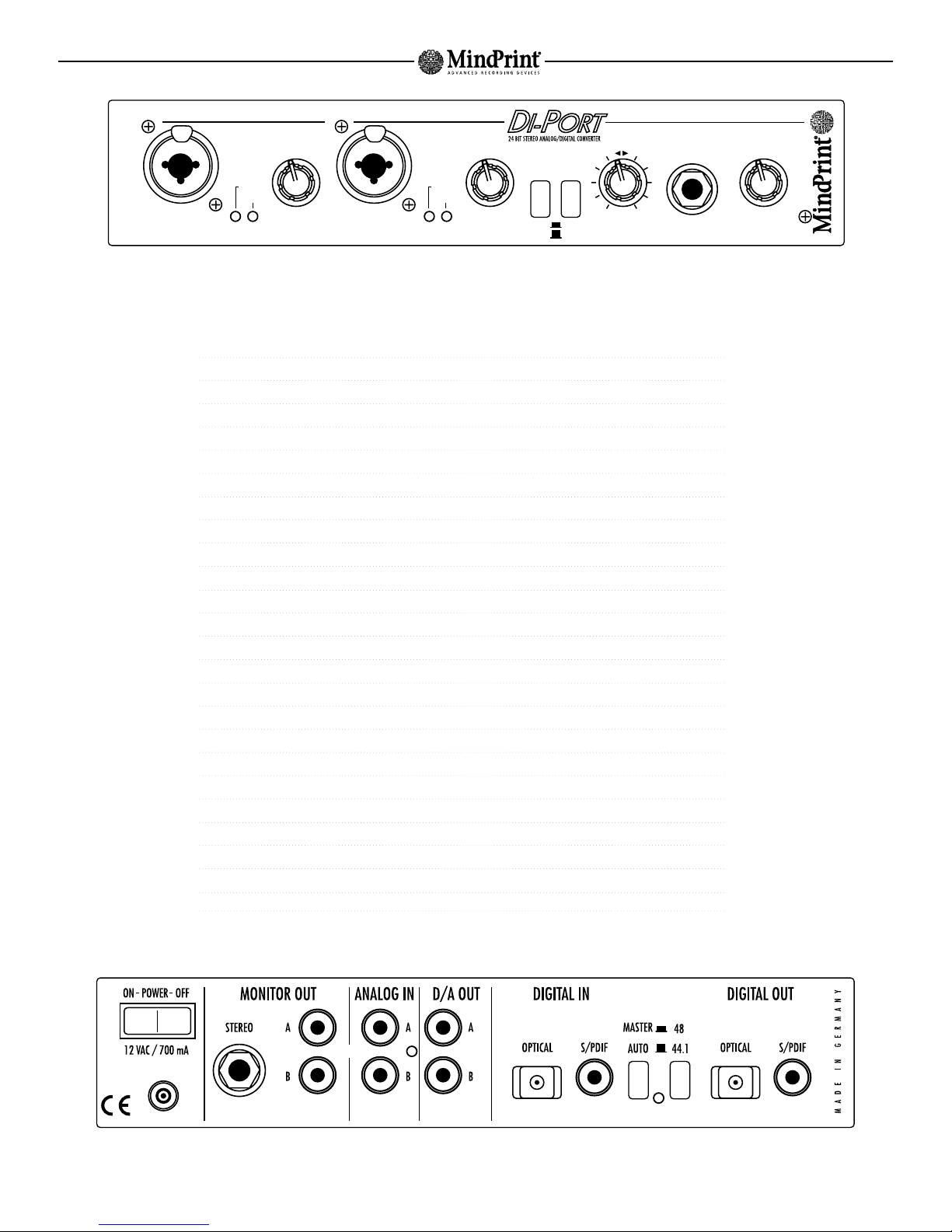
1. Layout of the DI-PORT
1.1 Analog Input/Output Section
The DI-PORT is equipped with a complete stereo input section comprising two micro-
phone/line inputs on the front panel as well as two line inputs on the rear panel. The
microphone inputs feature switchable 48-volt phantom power for capacitor microphones.
The microphone input stage is of the highest quality - not only does it outperform every
soundcard on the market, it also puts the microphone/line inputs of virtually all standard
mixers to shame. In addition, the output section, fully loaded with a D/A output as well as
a separate monitor output, delivers uncompromising sound quality.
Housed in a practical desktop chassis and featuring handy multi-purpose combination
XLR/1/4” input jacks on the front panel, the DI-PORT is versatile enough to accommodate
all signal sources. Indeed, its primary purpose is to serve as a universal converter for
every project studio. The Front/Rear input selector switches back and forth between the
microphone/line input on the front panel and the line input on the rear panel to allow you
to patch together a permanent signal routing setup and never have to swap patch cords.
You don’t need phantom power when you connect dynamic or electret microphones.
However, capacitor microphones compliant with the international IEC 268-15 standard
require an operating voltage of 48 volts. These are generally the first choice in studio
applications. The DI-PORT is designed to provide this type of power, all you have to do is
activate the 48 V button.
1.2 GAIN Knobs and Level Controls
Use the Gain knobs to dial in suitable levels. These control features are enabled when you
use the microphone as well as the line inputs. On the one hand, you want the input signal
to be as high as possible, on the other, the Peak LED of the DI-PORT should not illuminate
in red. The green LED lights up when the device receives an incoming signal at its inputs.
In order to adjust levels as precisely as possible, you should activate your recording soft-
ware’s level meter. We didn’t equip the DI-PORT with this type of visual display because,
for one, recording software is substantially better suited to carry out this function and, for
the other, a high-resolution LED chain would have unnecessarily jacked up the price of the
device.
In contrast to analog gear, digital devices aren't designed to accommodate saturated
signals. To illustrate this point, please bear in mind that up to the final tenth of a decibel
below the clip threshold, the sound remains unaffected, but as soon as the signal level
crosses this threshold, the device will immediately generate extremely ugly distortion
universally dreaded digital clipping. On the other hand, if you dial in too low a level, this
inevitably causes the level of quantization noise to increase. This type of noise is
generated when the signal is digitized in a process called quantization. Here an infinite or
continuous analog signal is subdivided into a finite number of discrete digital values.
Historically, this problem made it rather difficult to dial in a suitable level on a
conventional A/D converter. It is imperative that a kind of buffer (so-called headroom) be
maintained to prevent the signal from crossing the threshold and begin clipping. However,
at the same time, headroom had to be kept as small as possible in order to hold
quantization noise down.
With the DI-PORT‘s 24-bit technology and superior dynamic range of up to 116 dB, these
two critical prerequisites are much easier to meet because you have much greater leeway
between the clip threshold and the level at which quantization noise is generated than is
the case with conventional converters. This means that when you’re dialing in recording
levels, you don’t have to go to great pains to exploit every last bit of available headroom
and struggle to squeeze out every last decibel. In a nutshell, the DI-PORT assures that you
end up with a satisfactory audio frequency signal-to-noise ratio for your recordings
without all the hassle that you may have experienced with conventional converters.
1.3 A/D and D/A Converters
After the premium preamp section has worked its audio magic, the signal is converted so
that it can be introduced into the digital domain. The converted signal is routed out via the
digital outputæunsurprisingly labeled Digital Outælocated on the rear panel of the device.
This output serves as a coaxial as well as an optical S/PDIF port. It routes both stereo
channels out to the gear that follows the DI-PORT in your signal chain, for example, the
digital input of your computer’s audio card. The word length (also called bit depth) of the
digital signal is 24 bits, which fully exploits the technical potential of the S/PDIF standard
right down to the last bit. However, you are of course free to use the DI-PORT with
conventional 16- bit equipment.
For your sampling frequency, you can chose from the standard 44.1 and 48 kHz settings,
which means that you can work in a format compatible with that of audio CDs and
professional DAT recorders as well as the consumer format. Use the rear panel selector
buttons to set the device to the same sampling rate as the rest of your post-converter
equipment.
Connect the digital output of your computer’s soundcard (or other digital recording
equipment) to the input labeled Digital In on the DI-PORT. This port can also handle optical
and coaxial S/PDIF formats. The audio signal is converted back to the analog domain at a
resolution of 24 bits. You can access this converted signal via the D/A outputs.
1.4 Monitor Section
The DI-PORT offers a unique monitor function. You may use the sockets labeled Monitor
Out to route out preamplified analog or digital input signals. The Mix knob located on the
front panel lets you blend the output signal of the D/A converter in with the analog signal
so that you can hear the two signals simultaneously. This means that, during recording,
you can hear the original signal and the recorded signal in sync with tracks that you are
playing back. Use the Volume knob to vary the level of the monitor output, which is also
routed in parallel to a headphone socket located on the front panel. This is a handy feature
because you don’t need to place the monitor amp within reach to adjust the volume of your
monitoring system. Instead, you can dial in the desired level directly on the DI-PORT and.
For monitoring purposes, you are of course free to route the signal that you are recording
to any given output of your recording software. There is however a drawback to this
option: You’ll be faced with a delay equivalent to the latency time of your audio system.
Although vendors are rolling out hardware and software products with ever less latency,
you still have to cope with a significant amount of delay, which makes layering tracks by
recording a new track while listening to previously recorded track nearly impossible. Even
musicians with unreal timing have a problem with the latency of many quality hardware
recorders that see widespread use.
When you’re using the DI-PORT for a signal feed to a hardware monitoring setup, you won’t
encounter these problems because the analog input signal remains in the analog domain
and is patched to the output without any delay whatsoever. Since the signal is not
converted, with the DI-PORT, the terms "lag-free monitoring" take on an entirely new
meaning: The device doesn’t just minimize latency, it avoids it all together.
1.5 Synchronization
As soon as you connect digital audio devices to one another, you have to sync up their
internal clock frequencies (sampling rates). Here one device is the master, it dictates the
clock rate to all other connected devices, which are called slaves. When you set the
DI-PORT to AUTO mode, it automatically operates as a slave if the incoming signal is
identified as a valid signal (Locked LED lights up). It accepts the incoming clock or
sampling rate and runs at this frequency. If the DI-PORT does not recognize the signal as a
valid input signal, it automatically switches to master mode and operates at the frequency
that you have selected, either 44.1 or 48 kHz. (Check the operating manual of your
soundcard for the correct master/slave settings).
8
In addition, the DI-PORT can receive a 44.1-kHz signal and at the same time send a 48-kHz
signal, or vice versa. For this purpose, the DI-PORT must be set to master mode. With this
option, two devices can actually be operated as masters. In this case, the DI-PORT
operates in slave mode on the receiving side and uses the incoming signal’s sampling
rate. On the send side, it is in master mode and routes the outgoing signal at the selected
frequency. These frequencies may not coincide.
Although it is possible, we recommend that you refrain from running two devices as
masters.
2. Control Features
In keeping with the signal flow in the device, the control features of the DI-PORT are
arrayed from left to right.
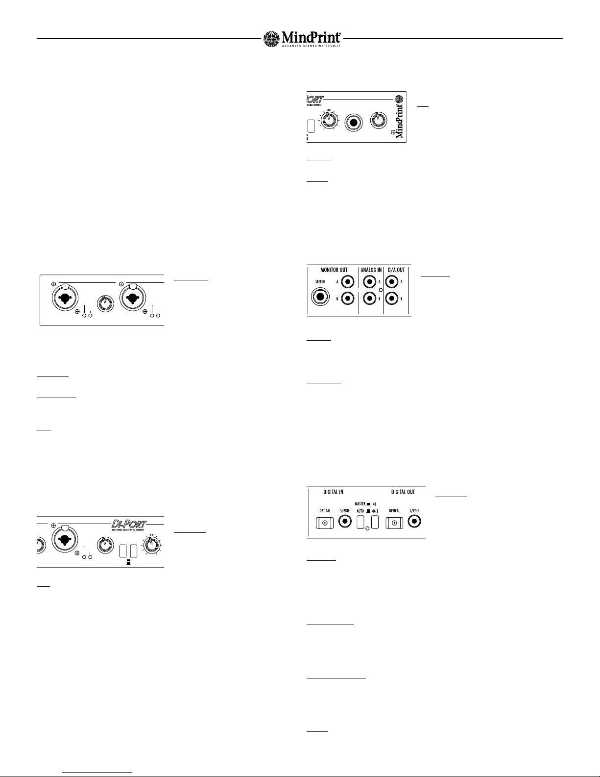
2.1 Preamplifiers
Mic/Line In: XLR input designed to take
microphones. The pin assignments of this
XLR socket comply with the international
norm IEC 268-12. In accordance with this
standard, Pin 1 is connected to the
ground, Pin 2 carries the positive signal
and Pin 3 the negative signal. If you use
this multi-purpose socket as a 1/4” jack plug, you can also insert line signals to it.
Green LED: This indicator lights up whenever a signal is routed to the input.
Red Peak LED: This indicator lights up to indicate the signal is clipping. In this case, use
the Gain knob to back off the input level.
Gain: Adjust the input level for the line or microphone inputs of the DI-PORT here. To fine-
tune and visually monitor levels, check out recording level meter of the digital device that
follows the DI-PORT in your signal chain. The peak LED of the DI-PORT indicates a
saturated signal, be sure it does not light up.
2.2 Input Selection and Phantom Power
Front/Rear: This button routes the micro-
phone/line inputs on the front panel or
the line inputs on the rear panel of the
DI-PORT to the A/D converter.
48 V: This button switches phantom power on, which is then fed to the connected
microphone. Dynamic microphones don't require phantom power. When you use capacitor
microphones, be sure to press this button.
2.3 Monitor Section
Mix: The monitor and headphones output patch out
a mix of the digital and analog input signal of the
DI-PORT. The Mix knob lets you blend these signals
to dial in the desired balance.
Volume: Use this knob to dial in the desired level for the headphones and monitor signal
Phones: Connect headphones here.
3. Rear Panel of the DI-PORT
3.1 Analog Connections
Analog In: These are 6.3 mm (1/4") input jacks
designed to take unbalanced line signals. You may
connect high-level signal sources such as
synthesizers, mixer outputs, the recording output
of a guitar amp, and the like here.
D/A Out: These two analog outputs route out the left and right channels of the signal that
is inserted into the digital input of the DI-PORT. This is a direct out circuit, meaning that
the Volume knob has no influence on the level of this signal.
Monitor Out: These analog outputs route out a mix of the digital and analog input signals
of the DI-PORT. Adjust the balance of signals via the Mix knob located on the front panel.
3.2 Digital Interface
The DI-PORT‘s is connected to digital circuits via an interface designed to handle coaxial
and optical S/PDIF formats.
Digital Out: Both channels of the converted
A/D input signal are routed out here.
Connect this port to the digital input of your
audio card.
Digital In: Digital input designed to convert the digital output signal of your computer into
an analog signal. The converted D/A signal is patched directly to the D/A Out port (see
above). In addition, this signal is also routed to the Monitor Out and can be blended in
with the analog input signal via the Mix knob. Connect Digital In to the digital output of
your audio card.
44.1 / 48 Button: This button selects a sampling frequency of 44.1 or 48 kHz when the
DI-PORT is operated exclusively as a A/D converter or is not receiving a valid digital input
signal. If on the other hand a valid digital signal is inserted into the digital input, the
DI-PORT adjusts its sampling rate so that it corresponds to that of the incoming signal.
Auto/Master Button: If you set the DI-PORT to Master, the device will operate with its
internal clock and its sampling frequency is determined by the 44.1/48 button. Set to Auto
mode, the DI-PORT is locked into sync with the signal routed into its digital input. The
device automatically adjust its sampling frequency accordingly.
Locked: This LED lights up as soon as the DI-PORT recognizes a valid digital signal at its
S/PDIF input.
MindPrint DI-PORT
GAIN A
5
0
3
2
4
1
6
7
8
XLR = MIC
JACK = LINE
ANALOG IN A
PEAK
ANALOG IN B
2
1
SIGNAL
XLR = MIC
JACK = LINE
PEAK
SIGNAL
FRONT
AIN A
5
4
6
7
8
48 V
ANALOG IN DIGITAL IN
GAIN B
ANALOG IN B
INPUTS
MIX
5
0
3
2
4
1
6
7
8
OFF
ON
XLR = MIC
JACK = LINE
PEAK
SIGNAL
REAR
LOCKED
48 V
ANALOG IN DIGITAL IN
PHONES VOLUMEMIX
5
0
3
2
4
1
6
7
8
MONITOR
OFF
ON
9
MindPrint DI-PORT
ENGLISH
In order to record analog line signal sources or microphone signals, simply connect these
to the appropriate inputs of the DI-PORT. Connect your monitoring system to the Monitor
Out outputs. If you own an analog recorder or want to patch an analog signal to your
external mixer, connect these devices to the D/A outputs of the DI-PORT.
To assure highest quality audio for your tracks, you should run your recording program at
a word length of 24 bits. If the program does not offer this option, or your digital card
does not support this resolution, or you aren’t willing to sacrifice the extra hard disk real
estate that a higher resolution requires, you can still use the DI-PORT to your benefit.
It is of course compatible with the 16-bit format and, even in this mode, the device is far
superior to the internal converter of a soundcardænot to mention its excellent microphone
preamplifiers featuring phantom power.
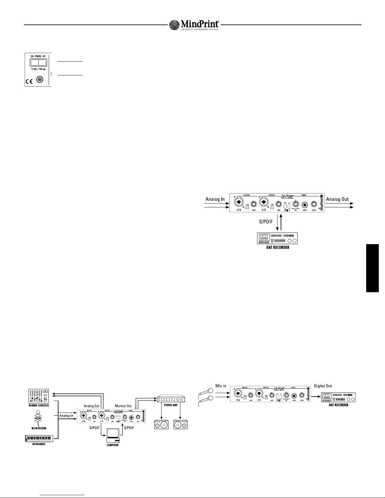
4.3 Converter for Digital Recorders
If in your studio you work with an analog mixer and record your mixdown to a DAT
recorder, you may have had good cause to be annoyed at the poor quality of its converter.
The DI-PORT remedies this problemæsimply use it as a converter for your recorder.
Connect the DI-PORT to your DAT, CD-R or MO recorder in both directions via the coaxial or
optical S/PDIF digital interfaces. The DI-PORT supports all word lengths of 16 to 24 bits
and sampling rates between 44.1 and 48 kHz, which means that it is compatible with all
standard recorders on the market.
When you opt for this type of setup, the analog busses of the DI-PORT respond just as if
they were part of the analog circuitry of your recorder. Furthermore, you can even use the
level meter of your recorder, provided that it is a digital rather than an analog meter. The
only difference lies in the handling of the control features. You must adjust levels via the
knobs on the DI-PORT rather than by means of the recorder’s controls.
4.4 Live Recording
Should you chose to deploy this device as a converter for a digital recorder, here's an
application option that might come in handy: live recording via a classic two-microphone
setup or a single-microphone setup when you need just two channels.
Most DAT recorders available to date are unsuitable for this application because they lack
microphone preamplifiers. The DI-PORT takes care of this problem and, with the benefit of
its high-quality microphone preamplifiers and onboard conversion that is executed
immediately right in the device, you can achieve excellent signal-to-noise ratios.
3.3 Power Supply
Mains Switch: Switches the DI-PORT on and off.
Mains Socket: Connect the DI-PORT to the mains power supply via an
external 12-volt 700mA AC adapter (wall wart).
4. Applications
4.1 The Purpose of the DI-PORT
Nowadays, the computer is the hub of the home recording studio. The majority of functions
found on professional devices of yesteryear, exorbitantly expensive just a decade ago, are
now standard features in contemporary hard disk recording systems. Fortunately, ever
more processing operations can be executed in the digital domain, which significantly
enhances the quality of productions. Today modern hard disk recording systems - in
conjunction with powerful computers - deliver the wide range of functions and number of
tracks that in the past you would’ve found only in the finest of studios. With a word length
of 24 bits, these systems deliver excellent audio specs for as long as the signal remains
in the computer.
However, interfaces have historically been a huge problem: The on-board converters of
soundcards work with 16 or 18 bits and frequently generate distortion. Moreover, since
these are installed inside the computer's housing, the signal-to-noise ratio is degraded
considerably by stray pick-up of clock frequencies. Finally, the high quality of computer-
based signal processing can’t in the final analysis be exploited fully, because the signal is
digitized by a soundcard that offers audio quality roughly comparable to that of a cassette
deck. Needless to say, we’re not talking ultra-high fidelity here.
The logical consequence is to deploy a high-quality converter housed in an external
device. Its signal is then transmitted digitally and loss-free to the computer. Not only do
the A/D and D/A converters of the DI-PORT work with 24 bits, they are also extremely
linear. Moreover, the device is chock full of high-quality analog circuitry. And, since it’s a
stand-alone device in a dedicated housing, it is immune to pick-up of stray interference.
With the DI-PORT, in combination with a digital I/O card (or the digital interface of a high-
quality soundcard), you will most definitely perceive a quantum leap in the definition and
quality of your audio. From this point forward, the level of fidelity that you can achieve
with this device is limited solely by the capabilities of your recording setup.
4.2 The DI-PORT as a High-end Audio Card
The DI-PORT’s primary purpose is to provide an outboard home to all analog components
and AD/DA converters that normally reside in the interior of the computer’s casing. Use it
in conjunction with a digital I/O card or the digital interfaces of quality soundcards, and
you will end up with a true high-end audio card.
Connect the digital output of the DI-PORT to the digital input of your computer and the
digital output of the computer to the digital input of the DI-PORT. In this setup, the
DI-PORT serves as an outboard converter unit for your digital audio card.
~
5
0
3
2
4
1
6
7
8
5
0
3
2
4
1
6
7
8
5
0
3
2
4
1
6
7
8
5
0
3
2
4
1
6
7
8
5
0
3
2
4
1
6
7
8
5
0
3
2
4
1
6
7
8
5
0
3
2
4
1
6
7
8
5
0
3
2
4
1
6
7
8
5
0
3
2
4
1
6
7
8

10
4.5 Analog Microphone Preamplifiers
Although the primary purpose of the DI-PORT is signal conversion, some users, impressed
by the high quality of its microphone preamplifiers, will want to use it in conjunction with
an analog mixer. This is anything but a problemæthe Monitor Out sockets can be used
specifically for this purpose. All you have to do is adjust the Monitor knob located on the
front panel so that solely the input signal of the DI-PORT is routed via this circuit. Simply
connect the Monitor Out sockets to two inputs of your mixer. With this setup, you can
exploit the excellent audio qualities of the microphone preamplifier even when you’re not
using the device’s converters.
5. Background Information
5.1 Disadvantages of Conventional Audio Cards
Soundcards are developed primarily as universal expansions in order to turn a PC into a
gaming or multimedia system. Their audio interfaces are just one feature among many:
A soundcard also offers a synthesizer-type sound generator, a joystick connection and a
MIDI port. If you ignore the features that are irrelevant to musical applications and focus
solely on the audio section, you can of course in principle use a soundcard as an audio
interface. However, bear in mind that cheap soundcards have serious drawbacks which
pretty much preclude the use of these for any serious musical application. Due to their
typical lack of linearity and poor signal-to-noise ratio, the audio quality of cheap
converters is very shoddy. Plus, due to the layout of motherboards, which aren’t designed
specifically for hard disk recording, cards often have to contend with pick-up of stray
interference, which becomes audible in the form of humming, hissing or whistling noises
emitted by the computer.
Many soundcards are equipped with power amp ICs that drive small multimedia
loudspeakers that are connected to the card’s outputs. If dedicated line outputs are
unavailable, you’ll encounter all kinds of compatibility problems and have to use adapters,
which will also degrade audio quality. Finally, many soundcards aren’t full-duplex enabled,
which means they are unable to record and play back signals simultaneously. As you can
well imagine, this functionality is absolutely essential, for example, when you want to
record a vocalist singing along with previously recorded tracks. Otherwise, for the obvious
reasons, the vocalist will have a hard time singing in time with something he or she can’t
hear. Therefore, for your musical endeavors, you are well-advised to opt for a high-quality,
full-duplex enabled audio card that is free of the problems we just discussed. However,
bear in mind that even if the card is equipped with decent converters, it can never cure an
inherent ill: By design, converters and analog components are installed in the interior of
the computer’s housing, which means that they are exposed to the considerable
electromagnetic interference prevailing inside a computer casing as well as interference
transmitted via the data bus and power supply.
This is why you should choose an audio card equipped with a digital interface or a pure
digital I/O card that you can operate in combination with the DI-PORT. Its preamplifiers
and converters are not only much better than those of standard audio cards, they are also
housed in an shielded outboard chassis that protects components from interference. In
addition, the DI-PORT is equipped with high-quality microphone preamplifiers featuring
phantom power. Not a single audio card currently available on the market offers
comparable features despite the fact that phantom power is something you can’t do
without when you’re using capacitor microphones,.
5.2 What Will 24 Bits Do for You?
When an analog signal is digitized, the level of the analog signal is measured at specific
intervals and represented numerically. The 16 bits of the CD format allow a representation
of 2 to the power of 16, which translates to 65,536 individual or discrete increments. If the
level of the initial analog signal lies somewhere between the discrete values of two of
these steps, the converted signal will contain an error. The size of this error varies with
each sample and is perceived by your ears as a type of interference called quantization
noise. On the other hand, a digital word length of 24 bits allows signals to be represented
by more than 16 million steps, which yields a considerably more accurate digital
approximation of the signal and hence significantly less quantization noise.
Incidentally, the superior 24-bit quality of the DI-PORT is beneficial - some might call it
imperative - even if the final product of the recording is a 16-bit CD. How so? Because
when you're recording with a 16-bit converter, in many cases only 14 bits are actually
used to represent the signal. The other two bits are reserved as a kind of digital
headroom. If the signal is compressed in the course of processing, quantization noise
- initially soft - becomes significantly more perceptible. Finally, during digital post-
processing, rounding errors are generated in computation operations. These errors are
always apparent in the lowest bit. For these reasons, it's a good idea to work with 24 bits
and refrain from converting the signal down to the 16-bit CD format until you've executed
all processing operations in your recording system. In other words, conversion should
always be the final step. The great advantage here is that the potential of the CD format is
exploited fully, right down to the last bit. Your tracks thus end up with the best possible
dynamic response, definition and fidelity.
6. Block Diagram
Page 30
7. Technical Data
Page 31
MindPrint DI-PORT

31
MindPrint DI-PORT
Technical Specifications
All levels are referenced to 0 dBV (1 V RMS )
Analog Inputs
LINE IN A+B:
Jack: 1/4“ ( Tip = +; Ring = ground ; Sleeve = ground)
Input type: unbalanced
Input impedance: 47 kΩ
Minimum sensitivity: -17.5 dB (for peak level)
Peak input level: +13.5 dB
Gain control range: 35 dB
MIC IN A+B:
Jack: XLR ( pin 1 = ground; pin 2 = +; pin 3 = - )
Input type: electronically balanced & floating
Input impedance: 10 kΩ
Minimum sensitivity: -47 dB (for peak level)
Peak input level -2 dB
Gain control range: 53 dB
Peak amplification: 75 dB
Phantom power: +48 V, switchable
ANALOG IN A+B:
Jack: RCA phono
Input type: unbalanced
Input impedance: 47 kΩ
Minimum sensitivity: -17.5 dB (for peak level)
Peak input level: +13.5 dB
Gain control range: 35 dB
Analog Outputs
D/A OUT A+B:
Jack: RCA phono
Output type: unbalanced
Output impedance: 57 Ω
Peak output level: + 8.9 dB
MONITOR OUT A+B:
Jack: RCA phono
Output type: unbalanced
Output impedance: 47 Ω
Peak output level: +17.5 dB
HEADPHONES:
Jack: 1/4” stereo ( Tip = Channel B; Ring = Channel A ;
Sleeve = ground)
Output type: unbalanced
Output impedance: 22 Ω
Output level: 300 mW @33 Ω
Digital Outputs (Compliant with IEC 958)
S/P-DIF
Jack: coaxial RCA
Output type: unbalanced, transformer isolated
Output impedance: 75 Ω
Peak output level: 500 mV
Data format: S/P-DIF
OPTICAL
Jack: TOSLINK
Digital Inputs (Compliant with IEC 958)
DIGITAL IN
Jack: coaxial RCA
Input type: unbalanced, transformer isolated
Input impedance: 75 Ω
Input sensitivity: 200 mV
Data format: S/P-DIF
OPTICAL
Port: TOSLINK
RESOLUTION: 24-bit
SAMPLING FREQUENCIES: 44.1 kHz; 48 kHz
CHANNEL STATUS: Consumer audio format
LATENCY: 0.8 ms @ 44.1 kHz
0.7 ms @ 48 kHz
SYNCHRONIZATION: switchable, internal / external
TOTAL HARMONIC DISTORTION A/A
LINE IN / MIC IN to MONITOR OUT
LINE IN (1 kHz sine wave): 0.001% @ -20 dB Input / 0 dB Output
0.002% @ -8 dB Input / 0 dB Output
0.0002% @ 0 dB Input / 0 dB Output
MIC IN (1 kHz sine wave): 0.006% @ -40 dB Input / 0 dB Output
0.001% @ -20 dB Input / 0 dB Output
0.007% @ -8 dB Input / 0 dB Output
TOTAL HARMONIC DISTORTION A/D
LINE IN/ MIC IN to S/P-DIF
LINE IN (fs= 44.1 kHz; 1 kHz sine wave): 0.1% @ -40 dBFS
0.011% @ -20 dBFS
0.002% @ -8 dBFS
0.003% @ -0.1 dBFS
MIC IN (fs= 44.1 kHz; 1 kHz sine wave): 0.09% @ -40 dBFS
0.01% @ -20 dBFS
0.005% @ -8 dBFS
0.006% @ -0.1 dBFS
LINE IN (fs= 48 kHz; 1 kHz sine wave): 0.12% @ -40 dBFS
0.011% @ -20 dBFS
0.0028% @ -8 dBFS
0.008% @ -0.1 dBFS
MIC IN (fs= 48 kHz; 1 kHz sine wave): 0.1% @ -40 dBFS
0.012% @ -20 dBFS
0.005% @ -8 dBFS
0.009% @ -0.1 dBFS
FREQUENCY RESPONSE A/D (@ fs = 44.1 / 48 kHz):
LINE IN: 20 Hz - 20 kHz, ±0.1 dB @ 0 dB / -0.1 dBFS
MIC IN: 20 Hz - 20 kHz, ±0.1 dB @ -20 dB / -0.1 dBFS
FREQUENCY RESPONSE D/A (@ fs = 44.1/ 48 kHz):
DIRECT D/A: 20 Hz - 20 kHz, ±0.2 dB @ 0 dB / -0.1 dBFS
MON D/A: 20 Hz - 20 kHz, ±0.3 dB @ 0 dB / -0.1 dBFS
FREQUENCY RESPONSE A/A:
LINE IN: 20 Hz - 20 kHz, ±0.1 dB @ 0 dB
MIC IN: 20 Hz - 20 kHz, ±0.1 dB @ -20 dB
DYNAMIC RANGE A/A: LINE IN / MIC IN to MONITOR OUT
LINE IN ( 0 dB): CH A: 110 / 105 dB (A-weighted/unweighted) @ 0 dB Output
CH B: 110 / 105 dB (A-weighted/unweighted) @ 0 dB Output
MIC IN (-20 dB): CH A: 103 / 98 dB (A-weighted/unweighted) @ 0 dB Output
CH B: 103 / 99 dB (A-weighted/unweighted) @ 0 dB Output
DYNAMIC RANGE D/A:
MONITOR OUT:
44.1 kHz: CH A: 103 / 99 dB (A-weighted/unweighted) @ 0 dB Output
CH B: 103 / 99 dB (A-weighted/unweighted) @ 0 dB Output
48 kHz: CH A: 103 / 99 dB (A-weighted/unweighted) @ 0 dB Output
CH B: 104 / 99 dB (A-weighted/unweighted) @ 0 dB Output
DYNAMIC RANGE A/D:
LINE IN (0 dB):
44.1 kHz: CH A: 105 / 101 dB (A-weighted/unweighted) @ -0.1 dBFS
CH B: 105 / 101 dB (A-weighted/unweighted) @ -0.1 dBFS
48 kHz: CH A: 103 / 101 dB (A-weighted/unweighted) @ -0.1 dBFS
CH B: 103 / 101 dB (A-weighted/unweighted) @ -0.1 dBFS
MIC IN (-20 dB):
44.1 kHz: CH A: 99 / 95 dB (A-weighted/unweighted) @ -0.1 dBFS
CH B: 99 / 94 dB (A-weighted/unweighted) @ -0.1 dBFS
48 kHz: CH A: 99 / 93 dB (A-weighted/unweighted) @ -0.1 dBFS
CH B: 99 / 93 dB (A-weighted/unweighted) @ -0.1 dBFS
CROSSTALK REJECTION A/A
LINE IN / MIC IN to MONITOR OUT
MIC IN (interchannel): > 76 dB @ 1kHz; -20 dB Input / 0 dB Output
LINE IN (interchannel): > 81 dB @ 1kHz; -20 dB Input / 0 dB Output
CROSSTALK REJECTION A/D
LINE IN / MIC IN to S/P-DIF
MIC IN (interchannel): > 76 dB @ 1kHz; -20 dB Input
LINE IN (interchannel): > 81 dB @ 1kHz; -20 dB Input
CROSSTALK REJECTION D/A
S/P-DIF to MONITOR OUT
MON OUT (interchannel):
> 82 dB @ 1kHz; 0 dB Output
GENERAL SPECIFICATIONS:
Different power supply versions,
230 Volt, 117 Volt, 100 Volt, Protection Class II
Max. current draw:
700 mA at 12.1 V AC ( Headphones Out: 2x 33Ω/ peak level )
Max. power consumption: 10.5 VA
Dimensions: 8.66” wide by 1.75” high by 7.09” deep
(220 mm x 44 mm x 180 mm)
Weight: 2.53 pounds (1.15 kg),
3.3 pounds with power supply (1.5 kg)
Table of contents
Other MINDPRINT Media Converter manuals


