DAC6820N (4) User Manual
-6-
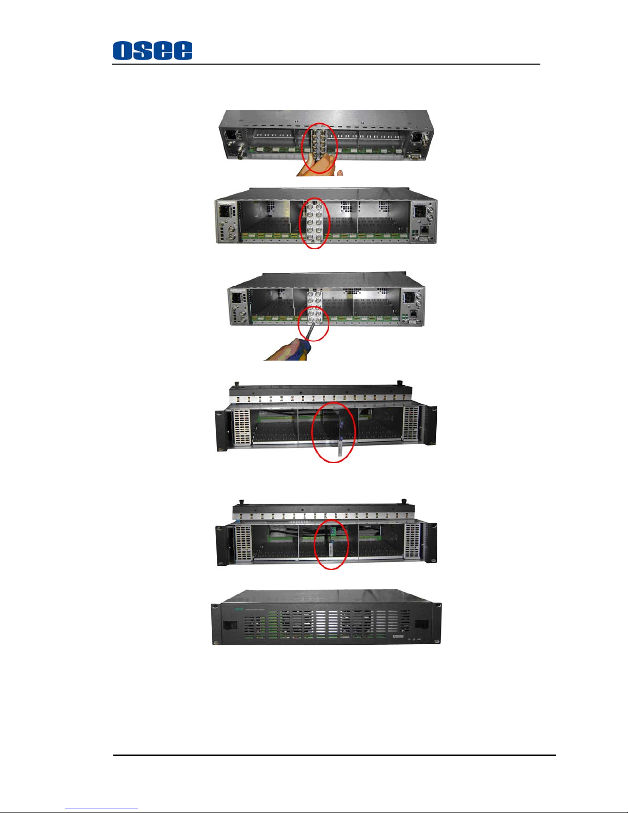
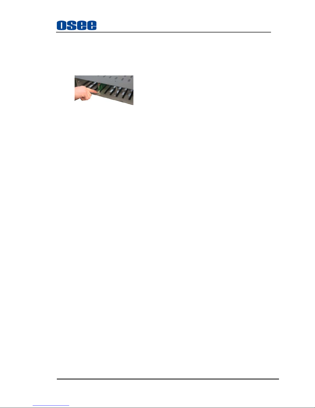
Removing the Module
Follow the following steps to remove DAC6820N (4) module:
1. Open the front part of frame.
2. Open the swivel handle to the full.
3. First make sure the frame stands firmly, and then pull the module gently along the slot till out
of frame.
4. Install the front panel.
Chapter 3 Operation and Control
Control
Directly turn the switch up for one second. Set “error is masked”. Here, it indicates that the
module can still receive data when the errors of QCRC, CCRC, UNLOCK, V, CONF, BIP and PAR
appear in the receiver port.
Turn the switch down for one second. Set “error is unmasked”. Here, it indicates that the
module can not receive data when the errors of QCRC, CCRC, UNLOCK, V, CONF, BIP and PAR
appear in the receiver port.
The definitions of seven types of errors in the receiver port are as follows.
1. QCRC – CRC error in Q subcode data.
2. CCRC – CRC error in channel status data.
3. UNLOCK – PLL is not locked to incoming data stream.
4. V – Data Validity bit is set.
5. CONF – The logical OR of UNLOCK and BIP. The input data stream may be near error
condition due to jitter degradation.
6. BIP – Biphase encoding error.
7. PAR – Parity error in incoming data.
Setting Jumper
Set the jumpers, which are JP1, JP2, JP3, JP4, JP5, JP6, JP7, JP8, JP9, JP10, JP11 and JP12, to
adjust the analog audio output level values from 16dB to 28dB.
Set the corresponding position of the jumpers, which are JP21, JP22, JP23 and JP24, to set the
balanced or unbalanced input of digital audio. The position of the jumper must be
corresponding to the real input audio.