Minerva Boskovice 4182i-1 User manual

upply for Mini-stops
4182i - 1
inerva Boskovice, a.s., Sokolská 60, CZ - 680 17 Boskovice
Tel.: +420-516-453434, 453433, 494111 Fax: +420-516-452165 http://www.minerva-boskovice.com
Edition/Vydáno/Herausgegeben/Edition/Editado: 05//2010 Printed/Tisk/Druck/Imprimé/Impress
o: Czech Republic 735 000689
Dodatek pro Mini-stopy
Nachtrag für Mini-stops
upplément pour Mini-stop
Aditamento para Mini-stop
www.promelectroavtomat.ru

ontents - The instructions for assembling with Mini-stops
1.Safety instructions 1
2.The way of machine supply 1
.1 Complete head with accessories 1
. Stand 1
3.Table top 2
4.Machine assembly 2
4.1 Stand frame assembly 2
4. Assembly of components on the bottom of table top and connecting to the mains 2
4.3 Assembly of a table top on a stand frame, assembly of oil tank 3
4.4 Assembly of machine head onto a stand 3
4.5 Electric connection of the machine head to the box of the drive electronics 4
451 Connecting cable4
452 Propper electric connection4
4521 DC 1550/DA3214
4522 HVP-70-4ED5
453 Fastening control panel of Mini-stop5
4531 DC 1550/DA3215
4532 HVP-70-4ED5
454 Fastening the thread stand6
455 Control of sewing by means of control elements6
4551 Via treadle6
4552 Via pushbutton panel6
5.Basic setting of the Mini-stop 7
5.1 Generally 7
5. Setting of Mini-stop EFKA DC 1550/DA3 1 7
521 Setting of parameters without the panel V810/V8208
522 Setting of positions8
523 Setting of the parameter of the microswitch of the running blocking when tilting the machine8
524 Changes of setting parameters of the Mini-stop with regard to the original setting of the manufacturer9
525 Control panels Efka V810/V82010
5251 Panel V81010
5252 Panel V82012
526 Indication of faults15
5.3 Setting of the Mini.stop HO HSING HVP-70-4ED 16
531 Setting of parameters on the panel of the control cabinet panel16
532 Setting of positions16
5321 Drive without external synchronizer16
5322 Drive with external synchronizer16
533 Setting of the parameter of the microswitch of blocking the machine running when tilting it16
534 Changes of parameter setting with regard to the original setting of the manufacturer17
535 Important parameters17
536 Functions of the panel on the control cabinet17
537 Panel of attendance C-30019
538 Conversion table of signs on display21
539 Error reports21
6.Examination of sewing 22
Table top 23
www.promelectroavtomat.ru

he instructions for assembling with Mini-Stops
1. Safety instructions
Caution !
Assembly of the machine must only be carried out by appropriately trained technician.
Any operations to be performed on the electric installation of the sewing machine are to be done only by a compe-
tent electrician.
SAFEY INSRUCIONS OF HE DRIVE MANUFACURER
The drive for the MINI-STOP sewing machines is manufactured and tested according to the valid safety regulations and enables
in this way a safe and dependable operation. For maintaining this condition and a safe running, the user needs to be acquainted
with all hints and cautions contained in these instructions, as well as in the instructions of the drive manufacturer.
The MINI-STOP is destined for the sewing industry and for being run in clean and dry rooms. It may not be put into operation
when the machine, in which it is incorporated, does not comply with all regulations and provisions. It is not allowed to use the
drive in outer humid spaces or in spaces with possible explosion risk. It is necessary to observe the hints of the manufacturer
concerning the running, attendance and maintenance. The MINI-STOP works in a safe and dependable way when there are
maintained the hints of the instructions and the purpose of the driver use. These instructions should be carefully read before
unpacking and putting the drive into operation. Before the first putting of the MINI-STOP, its accessories and supplements into
operation, be sure in being acquainted with the hints concerning the assembly, attendance, running and maintenance. All
activities connected with the drive may be carried out only when observing the respective regulations and when respecting the
given safety rules descreibed in the following parts of the indstructions. All persons concerned must be acquainted with these
safety warnings. The inobservance of these hints may cause injuries of persons, damage of objects or breakdowns or damage of
the drive.
It is necessary to observe the regulations concerning accidents, safety and skilled labour being in force in the given country.
The MINI-STOP may be installed and put into operation only by qualified persons. This will reduce to a minimum the consequences
of breakdowns with the possible health injury of persons.
Operations carried out on the machine or on its parts under high voltage are not allowed. Exceptions thereof are regulated by the
EN 500 standard.
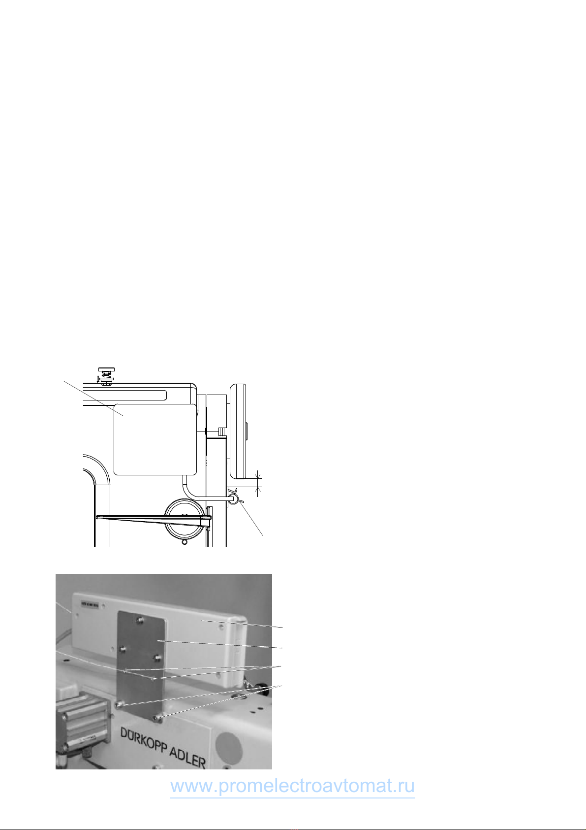
Before removing guards, assembling additional devices or accessories, e.g. sensors of the pedal position, photocell etc., the
drive must be disconnected from the mains and the drive must be put ito its idle condition. The operating box may be oppened
only after having run 0 minutes! wing to the risk of burning, fire, electric chock or injury, any reconstructions or eventual
modifications of the MINI-STOP are prohibited. During the running thereof, its guards or protective devices may not be removed.
Before leaving the work place, the mains switch must be out into the OFF condition. When the drive is out of use for some time,
the mains plug is to be disconnected from the mains and the drive must be secured against an accidental switching on.
In the event of having connected additional devices or operational means to the drive, these may be fed only with low voltage
from a safety transformer.
Never operate the drive when the air vents there of are clogged. Be sure in avoiding the presence of dust or fibres therein. Do not
insert and avoid falling of any object, e.g. needles, into these vents. Do not use MINI-STOP when working with aerosols and
sprays or with oxygen. The cautions mentioned in the following parts serve for ensuring further safety.
The MINI-STOP may be operated only with a protective conductor connected on a protective system which complies with all
regulations and service provisions.
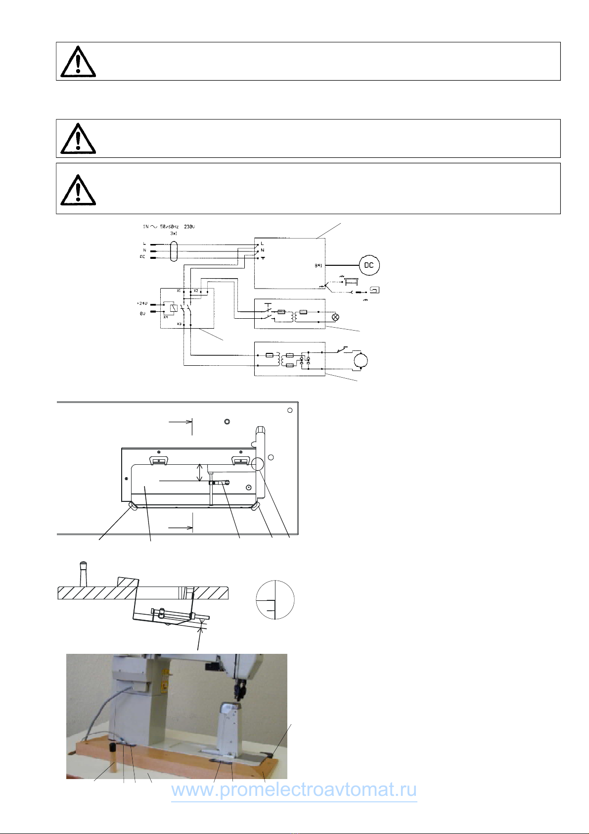
2. he way of machine supply
The contents of supply will be determined in agreement between the supplier and buyer. There are following possibilities:
2.1Complete head with accessories
In this case the supply contains:
-Complete head with motor, control electronics and connecting head cable.
-Chosen spare parts in the bag under the presser element (see parts indicated * in catalogue of spare parts).
-Standard accessories (it contains tools-see module in catalogue of spare parts).
-Special accessories (it contains some components of a stand and upper belt cover-see module in catalogue of spare parts).
The supply like this is not complete. Buyer will provide missing components himself or he can put in an extra order to get them
according to the following paragraphs.
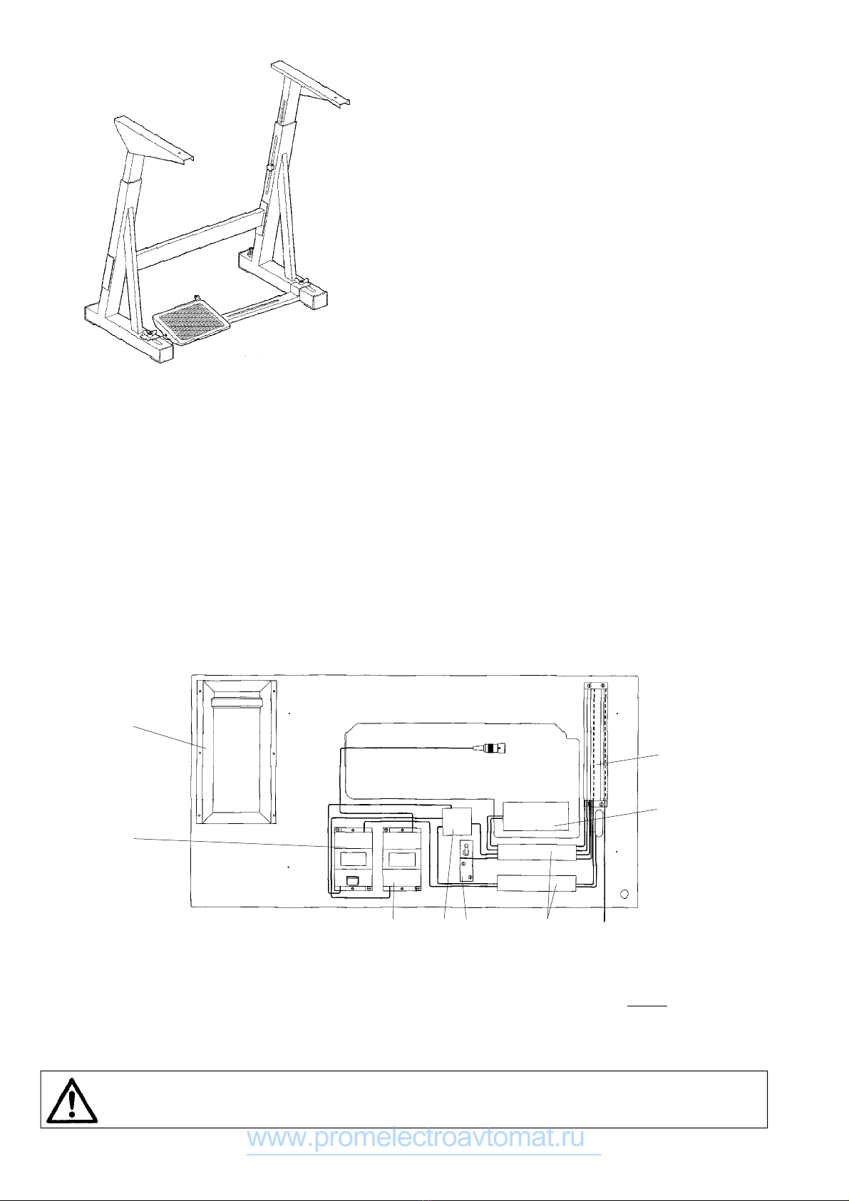
2.2Stand
Delivery contains components of a stand, however, without components of a stand included in special accessories supplied with
machine head (see par. 2.) and without any electrical components. If it hasn‘t been agreed otherwise, the stand is supplied in
separate pieces. If the assembled stand is asked, special accessories are used from head supply.
Stand (ordered number S400 09000 for subclasses with Mini-stop) contains following items:
MG55 00050 Stand frame
MG53 00250 Big treadle
MG53 0075Set of parts for a stand
S65 00038 Table top
www.promelectroavtomat.ru

2
3. able top
In case buyer will provide his own table top its drawing is
shown in supplement.
4. Machine assembly
It is described machine assembly with stand here which is
supplied in separate pieces. Otherwise use these instructions
adequate.
4.1 Stand frame assembly
A frame is assembled according to the picture.
4.2Assembly of components on the bottom of table top and connecting to the mains
-Put down antiskid (rubber) bands on the stand frame.
-Turn the table top its underside upwards and place it on the prepared bands.
-Screw on the drawer () using wood screws.
-Screw on the pedal position sensor holder (2) using wood screws and the pedal position sensor thereon using screws.
-Screw on the lighting transformer (3), if any, using wood screws.
-Screw on the trimmer feeder (5), if any, using wood screws.
-Connect the wiring box (6) lead to the terminals of the network lead of the electronics box (4) of the Mini-stop (8). For doing this,
it is necessary to remove the left-hand lateral from the electronic box.
-Screw on the box (4) of the Mini-Stop (8) electronics using wood screws.
-Screw on the wiring box (6) using wood screews.
-Connect the trimmer feed (5) to the terminals X3 in the wiring box (6).
-Connect the supply of the lighting transformer (3) (if any) to the terminals X2 in the wiring box (6).
-Screw on the installation ducts (9) using wood screws.
-Install the electric line of the network conductors using clamps. Place the conductors, led within the Mini-stop electronics box,
into the installation ducts.
The Mini-Stop is a device of the protection class I, which means that the protection against the dangerous contact of lifeless
parts is ensured by means of a protective conductor. The Mini-Stop is destined to be connected to an earthed alternating mains
with the voltage from 190 to 240 V 50/60 Hz. The connection thereof to the mains may be done only by means of a multipolar
plug with a protective contact. No fixed connection is permitted. Mind the uniform distribution of the power in the three-phase
mains. On every 16 A protected phase only 3 Mini-Stops may be connected, to avoid the overload of the medium conductor (N).
The MINI-STOP may be operated only with the protective conductor connected to a functional protective system
complying with all local regulations and provisions with regard to avoiding accidents of persons owing to electric
current or fire. This protection should not be cancelled e. g. by any extending cord without protective conductor.
2
1
3
65
4
8
9
www.promelectroavtomat.ru

3
The MINI-STOP will become dangerous when the protective conductor inside or outside the drive will be broken, as
well as with broken protective conductor with protective system.
Any intentional breaking thereof is forbidden.
The connecting conductors should comply with the power load and the min. HO5VV version. The conductor cross-section
should be at least mm2, The length thereof should not exceed 5 m. The voltage on the protective conductor should not exceed
3,3 V with the 0 A current.
Caution!
The voltage in the mains must be in conformity with the voltage indicated on the drive plate.
Caution!
The transformer of the bulb for the sewing area is not switched off by the main switch (EN 60204-3). Before
proceeding to any repair operation in the transformer box (such as a fuse exchange) the plug categorically must be
taken out of the socket. Such operations may be carried out only by persons with adequate electrotechnical skill.
4.3 Assembly of a table top on a stand frame,
assembly of oil tank
-Turn the table top around and screw it down to the frame by
means of screw ø8 x 35 mm.
When applying a frame different from that recommended by
the producer, be sure to adapt its position so as to ensure
the stability of the machine head in its tilted state.
-Screw on the microswitch (which is a component part of the
interconnecting cable) on the oil tank ().
-Oil tank () with assembled lever (2) insert through the bot-
tom part into the cut hole in the table top and put down as
shown in detail (D) in that way, that the edge of the tank
would fit in with the edge of the cut hole in the table top. Set
the height of the tank according to the section A-A. Tank
may not protrude out of upper surface of a table top. Nail
down the tank with nails ø2 x 40 mm.
-Adjust the lever (2) to the dimensions “B“ and “C“.
-Stick rubber inserts (3) into the cut-out of the table top.
4.4 Assembly of machine head onto a stand
-Stick down rubber inlays (2) with glue into the groove in a
wedge () and put the wedge down on the table top (3).
-Assemble hangers (4) on the head.
-Put the head down into the rubber inlays (2) and (5).
-Screw the wedge down to the table top with screws ø 5 x
30 mm.
-Screw on hinges, using wood screw ø 5 x 40 mm and screw
M5 (the hinge above the motor), to the table top. Tighten the
wood screw and the screw in such a way, so that the oscilla-
tion of the head on rubber inserts is not limited.
-Insert supporting pin (6).
Circuit layout
124346 2
5
4
6
A(ST2)
A-A D
B = ~82
A
A
3
3D1 2
C = 9mm
5
3
www.promelectroavtomat.ru

4
4.5 Electric connection of the machine head to the box of the drive electronics
4.5.1Connecting cable
Together with the machine head there is supplied a connecting cable for the drive.
For the information sake, there are given the respective circuit layout.
The colours are indicated with numbers in brackets (6 – green, 7 – blue, 8 – pink, 9 – black, 0 – white, – violet, 2 – yellow,
3 – red, 4 – grey, 5 – brown).
Power connecting cable is marked off with dotted line in circuit layout.
4.5.2Propper electric connection
4.5.2.1DC 1550/DA321
-Connect the 5-polar plug of the stator motor winding into
the socket B4 on the rear side of the electronics box.
-Connect the 9-polar plug of the commutation motor sensor
into the socket B2 on the rear side of the electronics box.
-Connect the 9-polar plug of the pedal sensor into the socket
on the rear side of the electronics box B80.
-Connect the 9-polar socket of the panel, if any, into the plug
on the rear side of the electronics box B776.
-Connect the 25-polar socket (3) of the connecting cable (2)
with the plug on the machine head, connect the 37-pole
plug of this cable into the 37-polar socket of the electronics
box A.
-Connect the 9-polar plug of the synchronizer IPG 00 into the
socket B8 (only for the gear ratio 26/36).
-Connect the plug of the wiring box (6) cable with the socket
of interconnecting cable.
-Connect the socket of the work trimmer power supply (5)
with the plug of the interconnecting cable.
-Secure all D-SUB connectors against falling out by screwing
in the screws.
-Place the cables into the installation ducts.
-Mount the lighting, if any, and connect its cable with the
transformer cable.
-Proceed to electric interconnecting of the motor head, hinge
(8), box of the Mini-Stop electronics and stand.
82 3
D
D
6
2
5
Circuit layout
www.promelectroavtomat.ru

5
4.5.2.2HVP-70-4ED
-Connect the 4-polar plug of the stator motor winding into
the socket M on the rear side of the electronics box.
-Connect the 9-polar plug of the commutation motor sensor
into the socket M on the rear side of the electronics box.
-Connect the 9-polar socket from the foot pedal into the plug
marked with the pedal symbol on the back side of the elec-
tronics cabinet.
-Connect the 9-polar socket of the panel into the plug marked
with the panel symbol on the back side of the electronics
cabinet.
-Connect the 25-pole (3) socket of the connecting cable into
the plug on the machine head, connect the 37-pole plug of
this cable into the 37-pole socket of the electronics cabinet.
-Connect the 8-pole plug of the synchronizer into the 8-pole
socket marked with the synchronizer symbol on the back
side of the electronics cabinet.
-Secure all D-SUB connectors against falling out by screwing
in the screws.
-Place the cables into the installation ducts.
-Mount the lighting, if any, and connect its cable with the
transformer cable.
-Proceed to electric interconnecting of the motor head, hinge
(8), box of the Mini-Stop electronics and stand (see detail
„D“).
4.5.3Fastening control panel of Mini-Stop
4.5.3.1DC 1550/DA321
-Stick the panel V8 0 or V820 () on the machine head (if
any). Defat the contact surface properly. Stick the clip (2) on
the cover belt.
4.5.3.2HVP-70-4ED
-Mount the control panel () of the Mini-stop, using the holder
(2 ) and the screws (3 ) on the machine head.
-For the thread guide, use the holes (4) of the holder, see
Figure.
1
2
60mm
2
1
3
4
www.promelectroavtomat.ru

6
4.5.4Fastening the thread stand
-Assemble the thread stand so that its arms would be parallel
to the longer edge of a table top.
4.5.5 Control of sewing by means of control elements
4.5.5.1Via treadle (treadle positions and function
possibilities)
Treadle Treadle Meaning
position
-2 Foot full backwards Command for thread
trimming (seam finishing)
- Foot slightly Commandlifting
the top roller up
0Neutral position Note
Slightly forwards Command releasing
top roller
2Continually Sewing at minimum
forwards speed (. gear)
> 2 More forwards higher speeds
ote: It is possible to pre-adjust the needle position (up/down)
and foot position (up/down) by stopping in seam (introduc-
ing the treadle in neutral position). Foot position (up/down)
after seam finishing (pressing the treadle by foot fully back-
wards).
4.5.5.2Via pushbutton panel
There are four built-in pushbuttons in the panel with fixed
adjustable functions:
T-bar operation (by pressing this pushbutton during se-
wing the sewn work is feed back)
T2-needle up/down (each press of the pushbutton changes
the needle position)
T3-temporary cancelling (recalling) bar (in case) the bar is
pre programmed at the start and end of the seam, by
pressing the pushbutton down will uniformly switch off;
if it is not chosen it will switch on by pressing the push-
button
T4-additional functions according to the stopmotor used
1 2 3 4
>0
0
-1 -2
www.promelectroavtomat.ru

7
5. Basic setting of the Mini-stop
5.1Generally
The Mini-stops do not necessarily need any control panels. All parameters can be set by means of press buttons and the display
on the electronics cabinet, the control panels will however enable the operative a more comfortable attendance owing to its
location.
5.2Setting of Mini-stop EFKA DC 1550/DA321
Elements of the electronics box
Front side
Button P calling or leaving the programming mode
Button E option of initial bartack (switched off, simple, double) within the programming mode of the confirmation
of changes
Button + option of final bartack (switched off, simple, double) within theprogramming mode of enhancing
the displayed value
Button - position of the presser foot when stopping in the seam (down, up)
position of the presser foot after trimming (down, up) within the programmed mode of reduction of
the displayed value
Button »position of the needle when stopping in the seam (down, up) within the programming mode of shifting to
the next digit
Segment indication for the start single bar
Segment 2 indication for the start double bar
Segment 3 indication for the end single bar
Segment 4 indication for the end double bar
Segment 5 ndication for automatic presser foot lifting when stopping in the seam
Segment 6 indication for automatic presser foot lifting after having ended the seam (trimming)
Segment 7 indication for stopping in the seam with the needle in its bottom position
Segment 8 indication for stopping in the seam with the needle in its top position
B20 USB connector for connecting the flash memory
C (B22) connection of the knee switch
Reae side
B2 connection of the commutating motor scanner
B8 connection of the light barrier module (photocell)
B4 connection of the motor stator winding
B80 connection of the pedal set value initiator
B776 connection of the panel V8 0/V820
A (ST2) connection of electric elements of the sewing machine (electromagnets, electropneumatic valves,
push-buttons …)
www.promelectroavtomat.ru

8
5.2.1 Setting of parameters without the panel V810/V820
The procedure is identical as with the panel V80/V820.
Procedure of changing parameters without the panel V810/V820
-depress the button P and then switch on the network switch on the front side of the electronics box, the display will show Cod
-depress the button », the st digit blinks
-using the button + and -, set the
st digit to the value 3
-depress the button », the 2
nd digit blinks
-in the same way, set the 2
nd, the 3
nd and the 4
rd digits, so that the display shows 3112 (the code number for the access to all
parameters)
-depress the button E, the display will show 2.0.0 (parameter number 200)
-using the buttons », + and -, set the required parameter number and depress the button E, the display will show the parameter
value
-using the buttons + and -, set the required parameter value
-depress the button E (the following parameter number will be displayed) or the button P (the original parameter number will be
displayed)
-proceed to the termination of changes by depressing the button P (you will leave the programming mode) and you will return
into the sewing mode
ote: To store the change in memory permanently, it is necessary to tread the pedal forward (sewing of at least one sticth) before
switching of the network switch.
5.2.2 Setting of positions
For correrct function of the machine, it is necessary to define the co-called reference position (angular setting of the machine with
regard to the drive). This is to be ensured by the parameter 170.
When removing the indented belt for any reason, it is necessary to reset the reference position (par. 70).
Procedure
-set the parameter number 170¸ depress the button E
-the display will show Sr1
-depress the button », Po will be displayed (the symbol o is rotating)
-turn the handwheel, until the rotating symbol o disappears and P is displayed
-turn now the handwheel to the value of the angle 105° (the needle point is at the level of the throat plate)
-depress 2x the button P (return into the sewing mode)
Other important positions, i.e the st position of the needle given by the parameter 171 1E and the 2nd position given by the
parameter 171 2 E have been preset by the manufacturer of the drive.
5.2.3 Setting of the parameter of the microswitch of the running blocking when tilting the machine
For the purpose of enhancing the safety of the operator of the machine and when unintentionally treading the pedal, the motor
running is blocked. To get a correct working of this function, it is necessary to mount a microswith (which is component part of
the interconnecting cable) on the rear side of the oil tray and to set the parameter 241 to the value 8. When the machine head is
in its working position, the microswitch must be switched on. The microswitch can be set when bending its lever.
www.promelectroavtomat.ru

9
5.2.4 Changes of setting parameters of the Mini-stop with regard to the original setting of the manufacturer
It is possible to change the parameters of the drive using :
-panel of the operating box
-external panel V8 0/V820
-memory USB flash (used in personal computers), files *.par:
par 5 0 – storing of parameters from DA32 on USB flash
par 5 – storing of parameters from USB flash into DA32
par 52 – comparison of parameters in USB flash and DA32
par 5 3 – erasure of the file from USB flash
For detailed information refer to the drive manufacturer.
Parameters for the machine with the gear ratio 36/36 teeth (without external synchronizer)
Parameter Parameter Parameter
number value description
290 class of the machine
- max. revolutions (according to the machine type)
70 - reference position
83 500 delay of switching-off of the trimmer motor after having finished stitching
2 5 0 the last forward section of the initial bartack counted
When it is not possible to set the parameter 290 on the value , it is necessary to set the following parameters:
Parameter Parameter Parameter
number value description
00 3 number of stitches in the section of the initial bartack
003 2 number of stitches in the section 3 of the final bartack
- max. revolutions (according to the type of machine)
6 80 revolutions of the thread cutter
70 - reference position
83 500 delay of switching-off of the trimmer motor after having finished stitching
2 5 0 the last forward section of the initial bartack counted
24 8 function A/
242 function A/6 needle upwards/downwards
Parameters for the machine with conversion 26/36 teeth (the external synchronizer is necessary)
Parameter Parameter Parameter
number value description
290 2 class of the machine
- max. revolutions (according to the machine type)
70 - reference position
83 500 delay of switching-off of the trimmer motor after having finished stitching
2 5 0 the last forward section of the initial bartack counted
When it is not possible to set the parameter 290 on the value 2, it is necessary to set the following parameters:
Parameter Parameter Parameter
number value description
270 6 selection of positioning
272 722 gear ratio
00 3 number of stitches in the section of initial
bartack
003 2 number of stitches in the section 3 of final bartack
- max. revolutions (according to the machine type)
6 80 revolutions of the thread cutter
70 - reference position
83 500 delay of switching-off of the trimmer motor after having finished stitching
2 5 0 the last forward section of the initial bartack counted
24 8 function A/
242 function A/6 needle upwards/downwards
47 6 regulation constant P
473 5 regulation constant D
www.promelectroavtomat.ru

0
5.2.5 Control panels Efka V 810/V 820
These functions are standardly assigned to the pushbuttons
A, B:
A-cancelling (recalling) the bar (the same function as T3 of
the pushbutton panel)
B-needle up/down(the same function as T2 of the push-
button panel)
ote: function of the A,B pushbuttons can be changed by
different adjustment of parameters 293,294 (see the parame-
ters list of driving unit Efka DA32 ).
5.2.5.1 Panel V 810
Functioning pushbuttons engagement:
Pushbutton P Recalling and program mode termination
Pushbutton E Confirmation of program mode changes
Pushbutton + Increase of value displayed in program
mode
Pushbutton - Decreasing value displayed in program
mode
Pushbutton Start bar SINGLE/DOUBLE/OFF
Pushbutton 2 End bar SINGLE/DOUBLE/OFF
Pushbutton 3 Automatic top roller lifting after stopping
at the seam ON/OFF
Automatic top roller lifting after thread
trimming (end of seam) ON/OFF
Pushbutton 4 Basic position of needle UP/DOWN
Pushbutton A For cancelling respectively recalling
the bar
Pushbutton B For switch over the needle position
UP/DOWN respective shift pushbutton
in program mode
Symbol C Connection of automatic revolutions
Symbol D Connection of lighting barrier
Symbol E The machine is running
Symbol F The revolutions limitation switch on
Symbol G Connection of lower thread controller,
flashing light indicator symbol when
the threads supply on the bobbin is
running out
The arrows on the display indicate switching the functions
which are displayed by symbols above the pushbuttons on.
Adjustment by means of buttons with fixed setting function
ote: It is important to finish the seam in order to reach
effective button pressing (press the treadle fully backwards
down).
Setting start bar:
Drive enables sewing start bar automatically. It is necessary to
choose the type (single, double, off) and number of stitches
which will be sewn forwards and backwards.
The arrow above its symbol shows the type of bar (chosen by
gradually pressing pushbutton ). It will be displayed follow-
ing after pressing pushbutton .
Arv (SAv) XXX - number of stitches of start (fancy) bar for-
wards or
Arr (SAr) XXX - number of stitches of start (fancy) bar back-
wards) for about 3 sec.
At this time you can change the number of stitches by gra-
dually pressing the pushbutton + or -.
www.promelectroavtomat.ru

Setting end bar:
The same applies to the start bar (setting by the means of
pushbutton 2).
Erv (SEv) XXX - end (fancy) bar number of stitches forwards
Err (SEr) XXX - end (fancy) bar number of stitches backwards
ote: The last section of end bar must have at least 3 stitches.
Foot position adjustment by stopping at the seam (by neutral
position of treadle) and after finishing seam (by neutral posi-
tion of treadle):
Setting is by means of pushbutton 3, arrow indication above
the corresponding symbol.
Needle position adjustment by stopping at the seam:
Setting is by means of pushbutton 4.
Setting by means of parameters
Drive memory contains the parameters which enables sewing
system tuning. These parameters have exact meaning and
they are divided into 3 levels. Further parameters which are
available only for operation will be quoted. Each parameter
has its (sequence) number and value.
General procedure by changing parameters of operation level:
-switch the main switch on or finish the seam by pressing the
treadle fully backwards down
-press pushbutton P on the panel V 80
-it will be displayed on the display F 000 (000 it is the number
of parameter)
-by several times pressing + (or -) set the requested number
of parameter
-push pushbutton E down and it will be shown the value of
parameter on the display
-you can change the value by means of pushbutton + or –
-by pushing pushbutton E down you will change the sequence
to the following number of parameter
-by pushing pushbutton P down you will leave the mode of
changing parameters
ote: .For permanent memory storing of changed pa-
rameter, it is necessary to press treadle forwards
down after changing of parameters.
2.Mode of changing parameters is possible only af-
ter finishing of the seam.
Procedure of changing parameters of the higher level
-depress the pushbutton P on panel and switch on thereafter
the main switch
-on the display there will appear C 0000, the st digit flashes
-using pushbutton + - set the
st digit on the value 3
-depress the pushbutton >>, the 2nd digit flashes
-in the same way set the remaining digits in the way to get
displayed on the display C 3112 (the number of the code for
the possibility of changing all parameters of the drive)
-depress the pushbutton E, on the display will appear F 200
(parameter number 200)
-using pushbuttons >>, +, - set the required parameter
number and depress the button E
-using pushbuttons +, - set the required parameter value
-depress the pushbutton E (a parameter number following in
the sequence will appear) or P (the same parameter number
will appear)
-carry out the termination of changes in depressing the
pushbutton P (return to the respective sewing mode)
You will find a detailed information in the original directins for
use of the drive (www.efka.net).
ote: To get the change of parameters permanently stored, it
is necessary, after having changed the parameter, to depress
the pedal in forward direction.
www.promelectroavtomat.ru

2
Number of stitches in bars:
Number of stitches is stored in parameter’s number.
No. of parameter Value range Description
of parameter of parameters
000(080) 0-254 Number of stitches of
start (fancy) bar forwards
00 (08 ) 0-254 Number of stitches of
start (fancy)bar backwards
002(082) 0-254 Number of stitches of
end (fancy) bar backwards
003(083) 0-254 Number of stitches of
end (fancy)bar forwards
Sewing according to sewing program:
Drive with panel V8 0 automatically enables sewing of seam
with setting number of stitches. It is necessary to set in corre-
sponding number of stitches, and initialisation of sewing pro-
gram.
No. of parameter Value range Description
of parameter of parameters
007 0-254 Number of stitches
0 5 ON/OFF ON/OFF sewing under
sewing program
ON/OFF thread trimmer:
No. of parameter Value range Description
of parameter of parameters
0 3 ON/OFF Thread trimmer
ON/OFF
5.2.5.2 Panel V 820
Functioning pushbuttons engagement:
Pushbutton P Call and termination of programming mode
Pushbutton E Confirmation when changing programming
mode
Pushbutton + Increasing the value displayed in program-
mingmode
Pushbutton - Reducing the value displayed in program-
ming mode
Pushbutton Start bar SINGLE/DOUBLE/OFF
Pushbutton 2 Stitch counting FORWARD/BACK/OFF
Pushbutton 3 Light barrier function
LIGHT-DARK/DARK-LIGHT/OFF
Pushbutton 4 End bar
SINGLE/DOUBLE/OFF
Pushbutton 5 Function
TRIMMING/TRIMMING+EJECTOR/OFF
Pushbutton 6 Automatic top roller lifting after having
stopped inside the seam ON/OFF
Automatic top roller lifting after trimming
ON/OFF
Pushbutton 7 Basic needle position UP/DOWN
Pushbutton 8 Lower thread waste controlling ON/OFF
Pushbutton 9 Operation pushbutton - programmable
Pushbutton 0 Programming/processing of 40 possible
sewing sections (seams)
A B
CD E F GH I JKLMNOPQ
www.promelectroavtomat.ru

3
Pushbutton A For cancelling or calling the bar
Pushbutton B For switching needle position UP/DOWN,
resp. shifting pushbutton in the program-
ming mode
Symbol C Designating symbol C for code number
Symbol D Designating symbol F for parameter
number
Symbol E Programme number in TEACH IN mode
Symbol F Seam number in TEACH IN mode
Symbol G Run blocking ON
Symbol H Blocked insertion by pushbutton
Symbol I Fault reporting
Symbol J Insertion of stitch number in TEACH IN
mode
Symbol K Connected lower thread controller, flash-
ing symbol when running out thread re-
serve on bobbin
Symbol L Limitation of revolutions ON
Symbol M Right needle disconnected
symbol N Evening stitches for light barriee in the
TEACH IN mode
Symbol O Machine is running
Symbol P Automatic revolutions ON
Symbol Q Left needle disconnected
The arrows on the display indicate switching the functions
which are displayed by symbols above the pushbuttons on.
Adjustment by means of buttons with fixed setting function
ote: It is important to finish the seam in order to reach
effective button pressing (press the treadle fully backwards
down).
Setting start bar:
Drive enables sewing start bar automatically. It is necessary to
choose the type (single, double, off) and number of stitches
which will be sewn forwards and backwards.
The arrow above its symbol shows the type of bar (chosen by
gradually pressing pushbutton ). It will be displayed follow-
ing after pressing pushbutton .
Arv (SAv) XXX - number of stitches of start (fancy) bar for-
wards or
Arr (SAr) XXX - number of stitches of start (fancy) bar back-
wards for about 3 sec.
At this time you can change the number of stitches by gra-
dually pressing the pushbutton + or -.
Setting end bar:
The same applies to the start bar (setting by the means of
pushbutton 4).
Erv (SEv) XXX - end (fancy) bar number of stitches forwards
Err (SEr) XXX - end (fancy) bar number of stitches backwards
ote: The last section of end bar must have at least 3 stitches.
Foot position adjustment by stopping at the seam (by neutral
position of treadle) and after finishing seam (by neutral posi-
tion of treadle):
Setting is by means of pushbutton 6, arrow indication above
the corresponding symbol.
Needle position adjustment by stopping at the seam:
Setting is by means of pushbutton 7.
Trimming switched ON/OFF:
To be set using pushbutton 5.
Sewing programme ON:
To be switched on using pushbutton 0.
Switching ON/OFF the function of the pushbutton F:
The pushbutton F on panel can have assigned one of the
following functions:Sst - softstart
SrS - fancy bar
Frd - reverse angle after trimming
A B
CD E F GH I JKLMNOPQ
www.promelectroavtomat.ru

4
Setting by means of parameters
Drive memory contains the parameters which enables sewing
system tuning. These parameters have exact meaning and
they are divided into 3 levels. Further parameters which are
available only for operation will be quoted. Each parameter
has its (sequence) number and value.
General procedure by changing parameters of operation level:
-switch the main switch on or finish the seam by pressing the
treadle fully backwards down
-press pushbutton P on the panel V 820
-on the display there is no data shown
-by depressing the pushbutton E several times, set the
required parameter (without having displayed the parameter
number)
-you can change the value using pushbuttons + or -
-by depressing the pushbutton E you will pass in the given
sequence to the following parameter
-by depressing the pushbutton P down you will leave the
mode of changing parameters
ote: .For permanent memory storing of changed pa-
rameter, it is necessary to press treadle forwards
down after changing of parameters.
2.Mode of changing parameters is possible only af-
ter finishing of the seam.
Procedure of changing parameters of the higher level
-depress the pushbutton P on panel and switch on thereafter
the main switch
-on the display there will appear C 0000, the st digit flashes
-using pushbuton 0 ÷ 9 set C 3112 on the display (code
number for possible changing of all drive parameters)
-depress the pushbutton E, on the display will appear F 200
(parameter number 200)
-using pushbutton 0 ÷ 9, set the required parameter number
and depress the pushbutton E
-using pushbutton +, - , set the required parameter value
-depress the pushbutton E (there will appear further param-
eter number in the given sequence) or P (return to the given
sewing mode)
-the termination of changes is to be done in depressing the
pushbutton P (return to the sewing mode)
A detailed information is in the original directions for use of
the drive (www.efka.net).
ote.: To get the change of parameters permanently stored, it
is necessary, after having changed the parameter, to depress
the pedal in forward direction.
Number of stitches in bars:
Number of stitches is stored in parameter’s number.
No. of parameter Value range Description
of parameter of parameters
000(080) 0-254 Number of stitches of
start (fancy) bar forwards
00 (08 ) 0-254 Number of stitches of
start (fancy) bar backwards
002(082) 0-254 Number of stitches of
end (fancy) bar backwards
003(083) 0-254 Number of stitches of
end (fancy) bar forwards
The drive with the panel V 820 enables sewing automatically
up to 40 seams distributed up into eight programmes with the
given stitch numbers and sewing direction (forwards/rear-
wards). For more detailed information see the original driving
instructions (www.efka.net).
A B
CD E F GH I JKLMNOPQ
www.promelectroavtomat.ru

5
5.2.6 Indication of faults
Generation information
Display of the V8 0 V820 Meaning
electronics box
A InF A InF A When switching on the machine, the pedal is not in the zero position.
-StoP- blinks +
A2 -StoP- blinks symbol blinks Blocking of the motor running.
A3 InF A3 InF A3 The reference position is not set.
A5 InF A5 InF A5 Autoselect not set or erroneous.
Programming of functions and values
Display of the V8 0 V820 Meaning
electronics box
Jump back to 000 Jumb back to 000
or to the last or to the last InF F Erroneous code or parameter number inserted.
parameter numberparameter number
Serious state
Display of the V8 0 V820 Meaning
electronics box
E InF E2 InF E External synchronizer (e.g. IPG) not connected or defective.
E2 InF E2 InF E2 Low woltage in the network or short period of time between the network switching on and off.
E3 InF E3 InF E3 Machine blocked or without attaining the required revolutions.
E4 InF E4 InF E4 Interference due to insufficient earthing or defective contact.
E9 InF E9 InF E9 EEPROM defective.
Hardware failure
Display of the V8 0 V820 Meaning
electronics box
H InF H InF H Commutation signal or invertor defective.
H2 InF H2 InF H2 Processor defective.
www.promelectroavtomat.ru

6
5.3Setting of the Mini-stop HO HSING HVP-70-4-ED
5.3.1Setting of parameters on the panel of the control cabinet panel
The access to the parameters is in 5 levels:
The level 1 enables changing parameters with the numbers until 46.
Procedure:
Switch on the mains switch (the LED display on the display lights up) and then depress the button P. The display will show 00 .H.
The number 00 indicates the parameter number. The letter H is a letter symbol of this parameter.In depressing anew P, the
parameter number increases (at the same time, the letter symbol changes) in the same way as with depressing „the initial bartack“
button. When depressing the button of the „final bartack“, the parameter number decreases. The parameter value related to the
parameter number will be displayed, if the button S is depressed. It is possible now to change the parameter value (each of them has
got its value limits) using the buttons A, B, C, D under the display. The storage of the changed parameter value will be done in
depressing the button S, and the return into the respective sewing mode is done by depressing anew the button S.
Note: The letter parameter symbol on the seven-segment display is not always well legible. The conversion table shows the
relation between the displayed value and the real letter.
The level 2 enables changing the parameters from to 22.
Procedure:
Before switching on the mains switch, depress and maintain the button P and then switch on the mains switch. The display will
show 047.MAC.
The following procedure is the same as with the access .
The level 3 enables changing parameters with the numbers from to the max.
Procedure:
Before switching on the mains switch, depress and maintain the button S and switch on the mains switch. The display will show
23. FAS.
The following procedure is the same as with the access .
The level 4 enables changing parameters with the numbers from to the max.
Procedure:
Before switching on the mains switch, depress and maintain the button „CHANGE OF NEEDLE POSITION“ and switch on the
mains switch. The display will show 76.vdn.. The following procedure is the same as with the access .
The level 5 enables changing parameters with the numbers up to the max.
Procedure:
Before switching on the mains switch, depress and maintain the button „SPEED CURVE“ and switch on the mains switch. The
display will show 208.vEr. The following procedure is the same as with the access .
5.3.2Setting of positions
5.3.2.1Drive without external synchronizer (synchronous gear ratio 1:1)
-set the parameter 236. SEL
-depress the button S, the display will show a value
-by means of the button D, change the value to 0 (236.SEL=0)
-depress the button P and set the parameter 8.PDA
-depress the button S, the display will show a value
-depress the foot pedal slightly forward, so that the machine performs at least 2 revolutions.
-turn the hand wheel into the position 05° (reference position, the needle tip is at the level of the needle plate)
-depress the button A (position storing)
-depress the button S
5.3.2.2Drive with external synchronizer
-set the parameter 236.SEL
-depress the button S, the display will show a value
-by means of the button D, change the value to 0 (236 SEL=)
-depress the button P and set the parameter 8.PDA
-depress the button S, the display will show a value
-depress the foot pedal slightly forward, so that the machine performs at least 2 revolutions
-turn the hand wheel into the position 05° (reference position, the needle tip is at the level of the needle plate)
-depress the button A (position storing)
-depress the button S
5.3.3Setting of the parameter of the microswitch of blocking the machine running when tilting it
For increasing the safety of the operator when tilting the machine and when accidentally depressing the foot pedal, it blocks the
motor running. For a correct function of this device, the mounting of this microswitch is necessary. (it is a component part of the
connecting cable) on the rear side of the oil tray and the parameter 075 on NC is to be set.
www.promelectroavtomat.ru

7
5.3.4Changes of parameter setting with regard to the original setting of the manufacturer
Parameter Parameter
number value
047.MAC 86 numeric code of the machine
001.H - max. sewing speed
060.L 50 st velocity stage
061. 180 trimmer revolutions
065.FC 40 magnet force for presser foot and bartacking
075.SFM NC tilting microswitch mode
083,T2 0 time of trimming after stopping in top position
085.LS 47 delay angle from switching on the trimming magnet up to releasing the tensioner
122.HL 3000 limit of max. revolutions
.ACT 200 running start
181.PDA see 5.3.2
236.SEL see 5.3.2
2 5.DK 500 delay of switching-off of the trimmer motor after having finished stitching
Note: It is necessary to set 047.MAC as the first parameter (machine class), which, after being changed, causes also the change
of further parameters.
5.3.5Important parameters
004.N 800 revolutions of the initial bartack
005.V 800 revolutions of the final bartack
006.B 800 revolutions for sewing patterns
007.S 400 revolutions of softstart
008.SLS 2 number of stitches of softstart
02.SMS SD current initial bartack
Adecorative initial bartack
020.SME SD current final bartack
Adecorative final bartack
04.(tm) ON/OFF on/off switching of the trimmer
5.3.6Functions of the panel on the control cabinet
Front side
Mains switch
Access to parameters
Storing of parameter
Initial bartack ON/OFF
Final bartack ON/OFF
Needle up/down
Softstart ON/OFF
Presser foot after stopping
Presser foot after trimming Display
Setting of number of stitches
www.promelectroavtomat.ru

8
Back side
Function of free sewing
DC 2V 50 mA
Connector C for
machine connecting
Synchronizer
Panel
of attendance
Connector B for
machine connecting
Connector D for
machine connecting
Motor
Motor encoder
Presser foot scanner
Connector A for
machine connecting
Change-over switch
Free seam/multiple bartack/seam
with constant number of stitches
Selection of
parameter number
Needle up/down
-if the machine is
out of operation
Softstart ON/OFF
Direction of motor
rotation
Number of stitches
Initial bartack ON/OFF
Final bartack ON/OFF
Presser foot after trimming
UP/DOWN
Presser foot after stopping in seam
UP/DOWN
Number of stitches on display
www.promelectroavtomat.ru
Other manuals for 4182i-1
3
This manual suits for next models
2
Table of contents
Other Minerva Boskovice Sewing Machine Accessories manuals