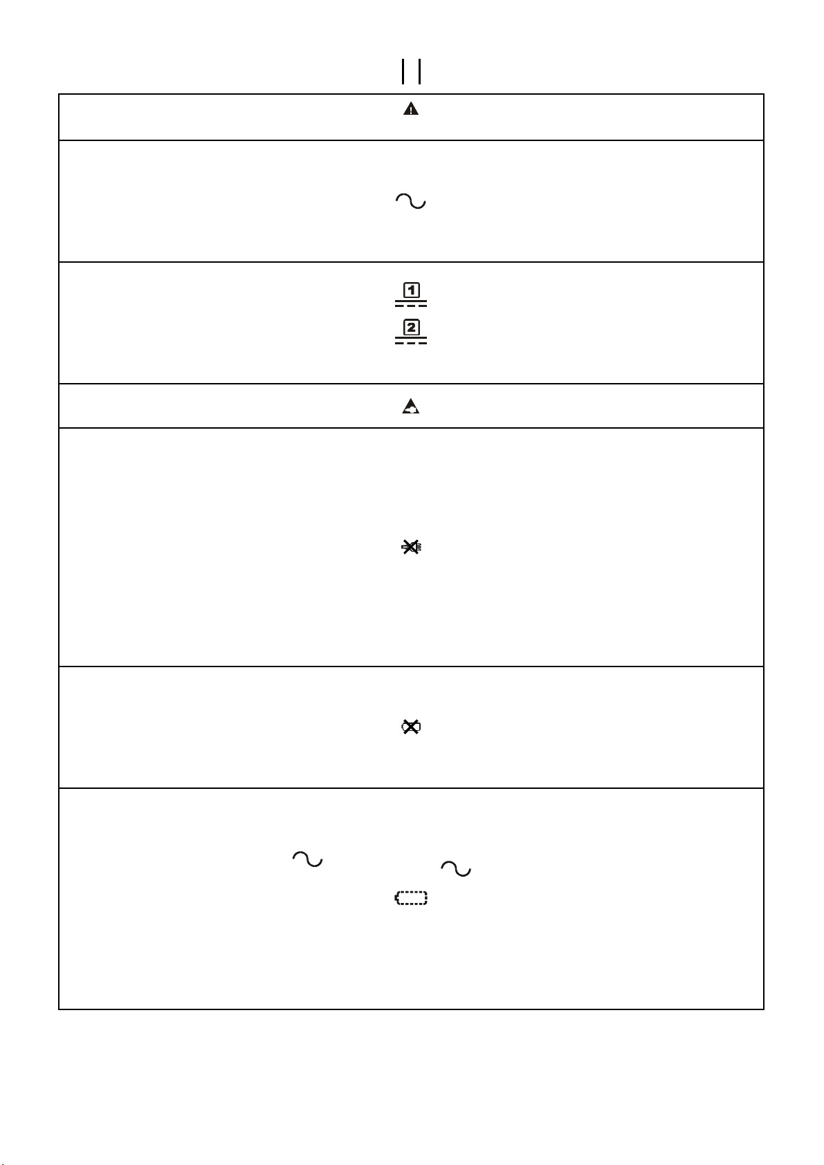
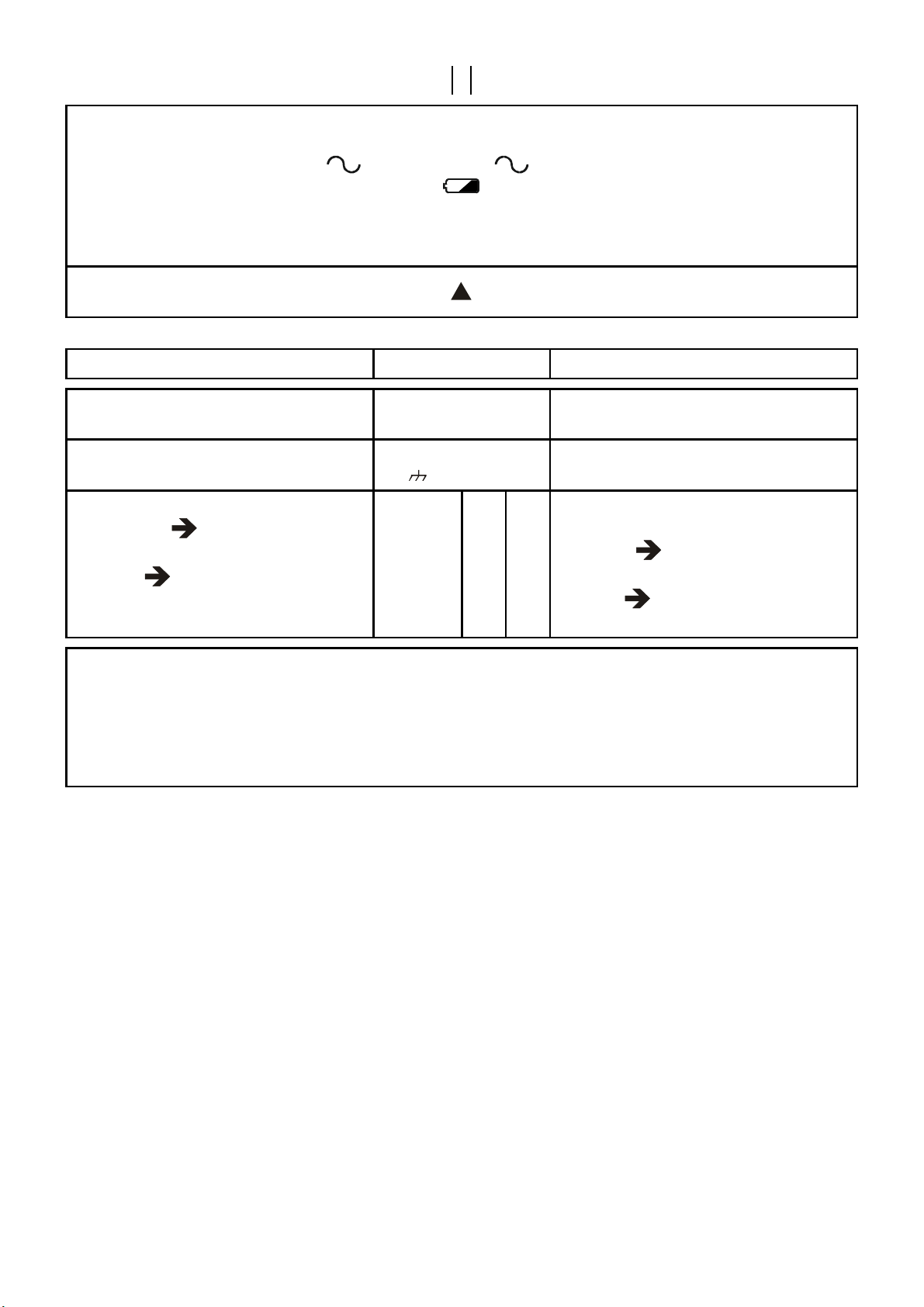
DESCRIZIONE DELLE SPIE WARNING LEDs
Se accesa indica presenza di un guasto
generico ON indicates Generic Trouble
Se spenta indica la mancanza della
tensione d’ingresso (230 V):
- controllare la presenza della tensione di rete;
- controllare che il fusibile 17 non sia bruciato:
- controllare che il Modulo Alimentatore sia
collegato all’Elettronica di Controllo.
OFF indicates input (230 V) voltage failure:
- check for Mains voltage;
- check that the fuse 17 is intact;
- check that the Power Supply Module is
connected to the PCB.
Se accese indicano la mancanza della
tensione di uscita rIspettivamente sui
morsetti [O1], o [O2]:
- controllare che la corrente assorbita dal
morsetto non superi 5A; se necessario
cambiare il fusibile 26 o 27.
ON indicates output voltage failure on
terminals [O1], or [O2] respectively:
- check that the current draw of the
terminal does not exceed 5 A. If necessary
replace the fuse 26 or 27.
Se accesa indica la presenza di un
guasto sul Modulo alimentatore ON indicates Power Supply Module
Trouble
Se accesa indica che il Modulo Alimentatore è
stato sconnesso perché la sua tensione di
uscita ha superato di 0,5V il valore previsto (il
valore di sgancio dipende dalla temperatura,
se è installato il dispositivo KST): nel frattempo
l’alimentazione della Stazione e dei dispositivi ad
essa collegati è garantita dall’accumulatore. Se la
tensione di uscita del Modulo Alimentatore torna
sotto la soglia di sicurazza, viene riconnesso
automaticamente, altrimenti esso deve essere
sostituito.
ON indicates that the Power Supply
Module has shutdown due to excessive
output voltage (over 0.5 V). The shutdown
value depends on the temperature (if the
KST termal probe is installed). The
standby battery will supply the voltage to
the Power Supply Station until the Power
Supply Module is restored. The Power
Supply Module will be restored
automatically when its output voltage
drops below the Safety threshold, if this
does not occur, it must be replaced.
Se accesa indica che l’accumulatore è stato
sconnesso perché la sua tensione è scesa
sotto la soglia di sicurezza ( 20,4V) che
potrebbe danneggiarlo in modo irreversibile.
Esso sarà riconnesso non appena il Modulo
Alimentatore sarà in grado di ricaricarlo.
ON indicates that the battery has shutdown
due to voltage drop (Safety threshold 20,4
V). This condition can damage the battery.
The battery will be restored as soon as it is
recharged by the Power Supply Module.
Se accesa indica che la Stazione di
Alimentazione è priva dell’accumulatore:
nel caso in cui venga a mancare la
tensione di ingresso (spia spenta)
l’alimentazione dei dispositivi collegati alla
Stazione è impossibile. Controllare che il
fusibile 19 sia intatto, che l’accumulatore
sia collegato e che la sua tensione non sia
inferiore alla soglia di sconnessione. In
quest’ultimo caso occorre sostituire
l’accumulatore.
ON indicates that the Power Supply
Station has battery trouble. Therefore, in
the event of input voltage failure (LED
OFF), the system will be unable to
feed the Power Supply Station peripherals.
Check that the fuse 19 is intact; - check that
the battery is connected and its voltage is
above shutdown threshold. The battery
must be replaced if the voltage remains
below the shutdown threshold.