Miniature Aircraft USA X-Cell Whiplash Turbine User manual

Table of Contents
Kit Introduction.................................................................................................................................. 3
R/C Helicopter Safety........................................................................................................................ 3
Warning...................................................................................................................................................3
General Guidelines .................................................................................................................................3
Academy of Model Aeronautics (AMA) ........................................................................................... 4
Kit Assembly...................................................................................................................................... 5
Required Tools ........................................................................................................................................5
Other Required Components ..................................................................................................................5
Assembly Tips ................................................................................................................................... 6
Kit Contents ....................................................................................................................................... 7
Flybarless Head Assembly (Whiplash Kit #MA1035-1 / -2).............................................................. 9
Flybarless Head Parts List ......................................................................................................................9
Flybarless Head Assembly Instructions ................................................................................................10
Flybarless Head Link Lengths...............................................................................................................11
Tail Assembly................................................................................................................................... 17
Tail Assembly Parts List ........................................................................................................................17
Tail Assembly Instructions.....................................................................................................................18
Frame Assembly.............................................................................................................................. 23
Frame Assembly Parts List ...................................................................................................................23
Frame Assembly Instructions................................................................................................................24
Electronics Mounting Positions .............................................................................................................33
Canopy Mounting..................................................................................................................................33
Basic Model/Radio Set Up .............................................................................................................. 34
Swashplate eCCPM Set Up............................................................................................................. 35
Pitch Curve Set Up .......................................................................................................................... 36
Throttle Curve Set Up...................................................................................................................... 37
Flybarless Stabilization Electronics .............................................................................................. 37
Kit Hardware and Parts................................................................................................................... 38
Warranty Information ...................................................................................................................... 39
Version 0.4 - Draft
01/04/2020
For updates to this manual, or any other Miniature Aircraft manual,
go to www.miniatureaircraftusa.com.
2

Kit Introduction
Thank you for purchasing the X-Cell Whiplash Turbine by Miniature Aircraft. This model is the culmination
of years of designing and manufacturing R/C helicopters. It is designed with the highest standards, and will
provide years of enjoyment. Whether this is your rst R/C model helicopter or you are an advanced R/C
helicopter modeler, the X-Cell Whiplash is a fantastic choice for a “700 size” turbine powered model.
R/C Helicopter Safety
A radio controlled model helicopter is not a toy, but rather a technically complex device that must be built
and operated with care. It is also a fascinating and challenging part of the R/C sport, the mastery of which
is very rewarding. A model helicopter must be built exactly in accordance with the building instructions.
The kit manufacturer has spent much time and effort rening this product to make it reliable in operation
and easy to build. The bolt together construction can proceed quite rapidly. This give the builder a strong
sense of accomplishment that encourages hasty progress from one construction phase to the next, so that
the completed model can be more quickly seen and enjoyed. It is essential to recognize and guard against
this tendency. Follow building instructions exactly. Vibration and stress levels are high and all fasteners and
attachments must be secure for safe operation.
Note that this is the rst use of the word SAFETY in these comments. Previously the kit manufacturer’s efforts
to ensure reliable operation were mentioned. That is ALL that he can do. Safe operation is the responsibility
of the builder/yer and starts with careful construction and continues with selection and installation of reliable
radio equipment and power systems.
The need for safety is nowhere greater than at the ying eld. A number of guidelines for safe ight have
been developed by experienced yers and are set down here. It is urged that they be read, understood and
followed. Always have a ready to use CO2 re-extinguisher (at least 2kg of CO2) next to the place where you
start the Whiplash turbine engine.
Warning! – Risk of death or serious injury
Remote Control (“R/C”) Helicopters can be dangerous. Inexperienced pilots of R/C Helicopters should
be trained and supervised by experienced operators. All operators should use safety glasses and other
appropriate safety equipment. All operators should exercise necessary precautions when fueling, repairing,
maintaining, ying and storing R/C Helicopters, and when using or storing R/C Helicopter accessories,
equipment, fuels, and related materials. R/C Helicopters should be used only in open areas free of obstacles
and far enough from people to minimize the possibility of injury from the helicopter or any of its components
falling or ying in unexpected directions.
This helicopter is not a toy but a complex ying machine that must be assembled with care by a responsible
individual. Failure to exert care in assembly, or radio or accessory installation, may result in a model incapable
of safe ight or ground operation. Rotating components are an ever present danger and source of injury to
operators and spectators. Since the manufacturer and his agents have no control over the proper assembly
and operation of his products, no responsibility or liability can be assumed for their use.
General Guidelines for Safe R/C Helicopter Flight
• Fly only at approved ying elds and obey eld regulations. Fly only if there are other people at the eld.
• Follow frequency control procedures. Interference can be dangerous to all.
• Know your radio. Check all transmitter functions before each ight.
• Be aware that rotating blades are very dangerous and can cause serious injury.
• Never y near or above spectators or other modelers.
• If you’re a beginner, get help trimming the model rst and seek ight training later.
• Don’t “track” the main blades by holding the tail boom. This is a temptation to builders who cannot hover yet
and is very dangerous.
3

Academy of Model Aeronautics
Miniature Aircraft highly recommends joining the Academy of Model Aeronautics (AMA).
• AMA is the Academy of Model Aeronautics.
• AMA is the world’s largest model aviation association, representing a membership of more than 195,000
from every walk of life, income level and age group.
• AMA is a self-supporting, non-prot organization whose purpose is to promote development of model
aviation as a recognized sport and worthwhile recreation activity.
• AMA is an organization open to anyone interested in model aviation.
• AMA is the ofcial national body for model aviation in the United States. AMA sanctions more than one
thousand model competitions throughout the country each year and certies ofcial model ying records on
a national and international level.
• AMA is the organizer of the annual National Aeromodeling Championships, the world’s largest model
airplane competition.
• AMA is the chartering organization for more than 2,500 model airplane clubs across the country. AMA offers
its chartered clubs ofcial contest sanction, insurance, and assistance in getting and keeping ying sites.
• AMA is the voice of its membership, providing liaison with the Federal Aviation Administration, the Federal
Communications Commission, and other government agencies through our national headquarters in Muncie,
Indiana. AMA also works with local governments, zoning boards, and parks departments to promote the
interests of local chartered clubs.
• AMA is an associate member of the National Aeronautic Association. Through NAA, AMA is recognized by
the Fédération Aéronautique Internationale (FAI), the world governing body of all aviation activity, as the only
organization which may direct U.S. participation in international aeromodeling activities.
For more detailed information, contact the Academy of Model Aeronautics
5161 E. Memorial Drive, Muncie, Indiana, 47302
or telephone (800) 435-9262.
You may also visit the AMA website at www.modelaircraft.org
4

Kit Assembly
Your Whiplash kit will require a number of different supplies and tools to ensure the best nal result. They are
as follows:
Required Lubricants and Compounds:
1. Medium Strength Thread Locking Compound - Loctite Blue #243 (MA3200-20)
2. Synthetic Grease (MA3200-06)
3. Retaining Compound - Loctite Green #648 (MA3200-22)
Required Tools:
1. M4 Nut Driver
2. M5 Nut Driver
3. M5.5 Nut Driver
4. M7 Nut Driver
5. 1.5mm Allen Driver
6. 2.0mm Allen Driver
7. 2.5mm Allen Driver
8. 3.0mm Allen Driver
9. 4.0mm Allen Driver x2
10. 5.0mm Allen Driver
11. Needle Nose Pliers
12. Phillips Screwdriver
13. Razor Knife (X-acto)
14. 2x Ratchet & Socket M10, M13
15 Dail Gauge resolution of 0.01mm / 0.0004” or better
Other required components:
The X-Cell Whiplash is an airframe kit. To complete the model, several other items are required, but not
included with the kit. There are many choices for these other required components, and any competent
hobby retailer with R/C helicopter experience will be happy to make suggestions. You will need:
1. Engine: Turbine Solutions 45i Whiplash Edition or Wren 44i.
2. Cyclic servos (Miniature Aircraft recommends high quality digital cyclic servos with no less than 80 oz.
in. of torque.)
3. R/C helicopter ybarless system
4. Rudder servo suitable for use with the gyro you choose. Digital servo is recommended.
5. R/C helicopter transmitter and receiver with at least 8 channels, telemetry capabilities are recomm.
6. 700-720mm Main Blades and 105-115mm Tail Blades.
8. R/C helicopter fueling equipment.
9. R/C helicopter engine governor (Futaba GV-1, GY701, CGY 760 or 750) are recommended.
10. CO2 re-extinguisher for operating the turbine engine
5

Important Assembly Tips - PLEASE READ
• Follow the instructions. The methods of construction documented in this manual have been proven to work.
Do not rush the build of your model! You have purchased a world class model helicopter kit, take your time
and realize that the nal result is now up to you. Take the time to fully understand each step and if you are
unsure please contact Miniature Aircraft, or a representative.
• Follow the order of assembly. The instructions have been organized into major sections and have been
written in such a way that each step builds upon the work done in the previous step. Changing the order of
assembly may result in unnecessary steps.
• Be sure not to overtighten bolts as damage to bearings and other components will occur.
• It is very important to lightly sand the edges of all carbon ber pieces. Miniature Aircraft recommends doing
so prior to the assembly process. Carbon ber edges can be sharp and can easily cut component wires and
battery mounting straps. It is important to use safety precautions when creating carbon ber dust. The use
of a particulate mask, preferably one with a P100 HEPA lter is recommended. Always clean up carbon ber
dust with a damp rag right away.
• Use thread lock as indicated. Generally any bolt or screw that threads into a metal part requires thread lock.
Model helicopters are subject to vibration and failing to use thread lock on any non-locking assembly may
result in a part becoming loose or falling off in ight.
6

Bag Part No. Part Description Qty
1-A 0217 Swashplate - Factory 1
1-Hardware 0051 M3x3 Set Screw 2
1-Hardware 0107 M3x6 Threaded Steel Ball 3
1-Hardware 0109 M3x8 Threaded Steel Ball 4
1-Hardware 131-83 Anti-rotation Pin 1
1-B 0869 Washout Link 2
1-B 128-176 Washout Pin 2
1-B 128-195 Head Button 1
1-B 128-314 Swashplate Follower - Factory 2
1-B 131-368 FBL Head Block 1
1-Hardware 0067 M3x14 Socket Bolt 1
1-Hardware 0071 M3x18 Button Head Socket Bolt 2
1-Hardware 0447-1 M2 E-clip 2
Bag Part No. Part Description Qty
1-C 131-161 Main Blade Grip - Factory 2
1-C 131-163 FBL Pitch Arm 2
1-C 131-187 Head Axle 1
1-Hardware 0107 M3x6 Threaded Steel Ball 2
1-Hardware 0061 M3x8 Socket Bolt 4
1-Hardware 0086-1 M5x16 Flanged Socket Bolt 2
1-Hardware 120-7-1 5x15 Safety Washer 2
1-Hardware 131-183 Washer 2
1-D 0133-1 M3x21.5 Ball Link 10
1-D 121-4 Servo To Swash Linkage Rod 3
1-D 121-7 Swash To PA Linkage Rod 2
1-D 131-408 FBL Main Shaft 1
1-Hardware 0021 M4 Lock Nut 1
1-Hardware 0023 M5 Nut 2
1-Hardware 0063 M3x10 Socket Bolt 2
1-Hardware 0082-4 M5x32 Shouldered Socket Bolt 2
1-Hardware 131-200 M4x33 Shouldered Socket Bolt 1
Kit Contents
Please take some time to familiarize yourself with the contents of the kit. The Whiplash kit has been broken down into
three “bags.” Each bag contains parts and hardware. The hardware in each bag will be used only for that bag. There
will be no left over parts after each bag is assembled. The individual parts of the factory assembled parts are not listed
out here. They can be found in the components section of the manual.
Bag 1 - Whiplash Rotor Head FBL
Bag Part No. Part Description Qty
2-A-1 131-475 T/R Pitch Slider Assembly - Factory 1
2-A-2 131-129 Tail Box Assembly - Factory 1
2-A-3 131-130-B Tail Pitch Control Bellcrank 1
2-A-3 131-131 C/F Bellcrank Bracket 1
2-A-3 131-132-B Bellcrank Slider Cup 1
2-Hardware 0019 M3 Lock Nut 1
2-Hardware 0064-3 M3x6 Button Head Socket Bolt 2
2-Hardware 0073 M3x20 Socket Bolt 1
2-Hardware 0107 M3x6 Threaded Steel Ball 1
2-A-4 131-64 T/R Hub 1
2-A-4 131-112 T/R Blade Grip - Factory 2
2-Hardware 0009 M3 Washer 2
2-Hardware 0019 M3 Lock Nut 2
2-Hardware 0056 M3x5 Dog-Point Set Screw 2
2-Hardware 0061 M3x8 Socket Bolt 2
2-Hardware 0071 M3x18 Socket Bolt 2
2-Hardware 0107 M3x6 Threaded Steel Ball 2
2-B-1 131-400 TT Ends 2
2-B-1 131-480 TT Bearing Cup 3
2-B-1 131-481 TT Bearing Cup O-Ring 6
2-B-1 131-482 TT Sleeve 3
2-B-1 131-485 TT Bearing 3
2-Hardware 0015 2mm Hex Nut 2
2-Hardware 0049-1 M2x12 Socket Bolt 2
Bag Part No. Part Description Qty
2-B-2 133-458 TT 1
2-B-2 131-62 Tail Boom 1
2-B-2 128-142 T/R Control Rod 1
2-B-2 131-86 Tail Boom Support C/F Rod Assemly 2
2-B-3 0133 M2x21.2 Ball Link 2
2-B-3 128-80 Aluminum Front Boom Clamp 2
2-B-3 128-144 T/R Control Rod Guide 4
2-B-3 128-149a Upper Rear Boom Support Mount 1
2-B-3 128-149b Lower Rear Boom Support Mount 1
2-B-3 135-128 C/F Boom Clamp Plate 1
2-Hardware 0016-2 4mm External Serrated Lockwasher 2
2-Hardware 0060-1 M3x6 Socket Bolt 4
2-Hardware 0063 M3x10 Socket Bolt 2
2-Hardware 0065 M3x12 Socket Bolt 3
2-Hardware 0067 M3x14 Socket Bol 2
2-Hardware 0078 M4x12 Socket Bolt 2
2-B-4 133-60 C/F Vertical Tail Fin Painted 1
Bag 2 - Whiplash Tail Assembly
7

Bag Part No. Part Description Qty
3-A 128-57 3mm Tray Mount 6
3-A 131-52 Delrin Tray Mount 2
3-A 131-53 C/F Gyro Plate 2
3-A 135-55 C/F Angled Battery Tray 1
3-A 135-57 Spacer 1
3-A 135-383 Hopper Support 1 1
3-A 135-492 Hopper Support 2 1
3-Hardware 0032-2 M3x8 Tapping Screw 4
3-Hardware 0088-2 M3x6 Tapered Socket Bolt 14
3-Frames 135-487 C/F Left Frame - Turbine 1
3-Frames 135-488 C/F Right Frame - Turbine 1
3-Frames 135-115 C/F Bottom Plate 1
3-Hardware 0004 4mm Washer 10
3-Hardware 0032 2.9x9.5 Tapping Screw 4
3-Hardware 0060-1 M3x6 Socket Bolt 40
3-Hardware 0061 M3x8 Socket Bolt 40
3-Hardware 0063 M3x10 Socket Bolt 6
3-Hardware 0078-4 M4x8 Socket Bolt 6
3-Hardware 2700-01 3mm Blue Washer 35
3-B 128-58 Frame Spacer 6
3-B 128-90 Tank Plate Mounting Stud 4
3-B 131-46 P/A Servo Rail 2
3-B 131-47 C/F Servo Rail Spacer 2
3-B 131-186 C/F Anti-rotation Bracket 1
3-B 131-420 Mid Main Bearing Block 1
3-B 131-421 Upper Main Bearing Block 1
3-B 134-100 Engine Mount 1
3-B 135-104 T/R Drive Support 2
3-B 135-107 Rear Doubler 2
3-B 135-125 Front Canopy Spacer 2
3-B 135-429 C/F X-Brace 1
3-Hardware 0060-1 M3x6 Socket Bolt 4
3-Hardware 0063 M3x10 Socket Bolt 4
3-Hardware 0065 M3x12 Socket Bolt 4
3-C 0215 6mm Retaining Collar 1
3-C 127-86 Washer 2
3-C 131-3 Start Shaft w/Sleeve 1
3-C 131-117 Fan Hub 1
3-C 131-118 Shim Washer 1
3-C 131-119 Clutch 1
3-C 131-120 Fan 1
3-C 131-179 X-Block 1
3-C 131-411 Assembled Clutch Bell 1
3-C 135-101 Engine Support 4
3-C 135-103 Spacer 2
3-C 135-124 Turbine Mount 1
3-Hardware 0009 3mm Washer 4
3-Hardware 0051 M3x3 Socket Set Screw 2
3-Hardware 0064-3 M3x6 Button Head Socket 4
3-Hardware 0065 M3x12 Socket Bolt 2
3-Hardware 0069 M3x16 Socket Bolt 4
3-Hardware 0078-4 M4x8 Socket Bolt 2
Sensor Mount:
3-Hardware 0001 2mm Washer 4
3-Hardware 0016-2 4mm Safety Washer 4
3-Hardware 0018 2mm Lock Nut 2
3-Hardware 0049 M2x10 Socket Bolt 2
3-Hardware 0080 M4x14 Socket Bolt 2
3-Hardware 0081 M4x16 Socket Bolt 2
3-S 0818-3 Mounting Block 2
3-S 131-50 Elevator Servo Mount 2
3-S 131-148 C/F Servo Plates 14
S-Hardware 0017-2 2.5mm Hex Nut 5
S-Hardware 0059-1 M2.5x6 Socket Bolt 4
S-Hardware 0059-4 M2.5x12 Socket bolt 16
S-Hardware 0059-7 M2.5x20 Socket Bolt 4
S-Hardware 0116 M2.5 Threaded Steel Ball 5
Bag Part No. Part Description Qty
3-D 128-57 Spacer 1
3-D 128-58 Spacer 1
3-D 131-382 C/F Spacer 1
3-D 131-454 4mm Tray Mount 2
3-D 135-58 Spacer 1
3-D 135-380 White Strut II 2
3-D 135-382 C/F Strut Spacer 1
3-D 135-489 Lower Main Frame 2
3-D 135-490 C/F Frame Spacer R + L 2
3-D 135-491 C/F Washer 2
3-D 2500-39 Tuf-Strut II End Cap White 4
3-Hardware 0003 3mm Washer 4
3-Hardware 0058-1 M4x6 Socket Screw 4
3-Hardware 0064-3 M3x6 Button Head 6
3-Hardware 0073 M3x20 Socket Bolt 4
3-Hardware 0078-5 M4x10 Socket Bolt 4
3-E 0875-1 10mm Split Main Shaft Collar 2
3-E 131-424 Main Gear Hub 1
3-E 131-440 Lower Main Bearing Block 1
3-E 131-466 Auto Hub 1
3-E 131-469-1 Gear Support 1
3-E 131-470 70T Machined Crown Gear 1
3-E 132-117-B 124T Main Gear 1
3-Hardware 0021 4mm Lock Nut 1
3-Hardware 0059-2 M2.5x8 Socket Bolt 2
3-Hardware 0088 M3x8 Tapered Socket Bolt 8
3-Hardware 0088-3 M3x7 Tapered Socket Bolt 5
3-Hardware 0620-01 15x21x.10 Shim Washer 1
3-Hardware 0620-02 15x21x.20 Shim Washer 1
3-Hardware 0620-03 15x21x.30 Shim Washer 2
3-Hardware 131-202 Jesus Bolt OWB V2 1
3-E-1 106-22 Rubber Canopy Grommet 4
3-E-1 120-99 Canopy Knobs 2
3-E-1 128-59 M4 Front Boom Support Brace 1
3-E-1 131-153 C/F Canopy Breakaway Tabs 4
3-E-1 131-451 Rear Canopy Post 2
3-E-1 131-452 Canopy Post Splint 2
3-E-1 135-127 Boom Support Spacer 2
3-Hardware 0016-2 M4 External Serrated Lock Washer 2
3-Hardware 0015 2mm Hex Nut 1
3-Hardware 0081 M4x16 Socket Bolt 2
3-Hardware 0103 2mm Threaded Steel Ball 1
3-F 105-100 Fuel Line 9.5 cm 1
3-F 125-24 Fuel Filtered Pick-Up Magnet 1
3-F 128-92 Fuel Tank Plug 1
3-F 128-94 Fuel Nipple 1
3-F 131-138 Fuel Tank 1
3-F 131-144 Rubber Fuel Tank Mount 4
3-F 131-145 Tank Mounting Studs 2
3-F 131-146 C/F Fuel Tank Plate 2
3-F 135-133 Fanshroud R +L 2
3-Hardware 0011-5 Washer 1
3-Hardware 0014F 5mm Hex Nut - Fine Threaded 1
3-Hardware 0060-1 M3x6 Socket Bolt 4
3-Hardware 0061 M3x8 Socket Bolt 2
3-Hardware 0065 M3x12 Socket Bolt 4
3-G 0390 Wire Retainers 5
3-G 3200-30 20” Spiral Band for Wire and Cable 1
3-G 3200-46 1/2” Hook and Loop Tape 1
3-G 3200-48 20” 3/4 Hook and Loop Tape 1
3-G 3200-54 17” Adhesive Hook and Loop 1
BOX 135-252 Whiplash Canopy - Turbine 1
BOX 135-106 Hopper Tank 1
BOX 133-144 Skids
BOX 135-233 Whiplash Instruction Manual 1
BOX 3000-73 MA Towel 1
BOX 3700-160 Blade Holder 1
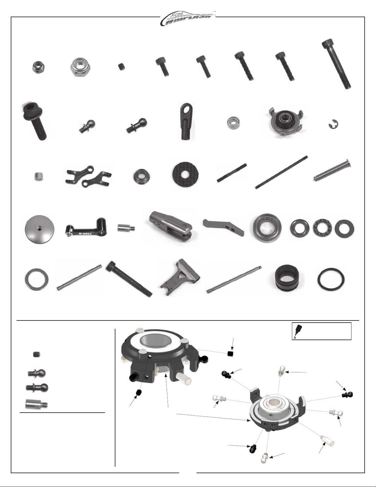
Bag 3 - Turbine Frame Assembly
8

0107
M3x6 Threaded Steel
Ball
0109
M3x8 Threaded Steel
Ball
0133-1
M3x21.2 Ball Link 0159
3x7x3 Bearing
0217
Swashplate
0447-1
E-Clip
0597-4
M3x4.75x.215 Brass
Spacer
0869
3D Washout Link
120-7-1
M5x15 Safety Washer
121-4
M3x30 Threaded
Control Rod
121-7
M3x65 Threaded
Control Rod
128-176
M2x.584 Washout
Pivot Pin
128-195
Aluminum Head Button
131-83
Swashplate Pin
131-161
Aluminum Blade Grip 131-163
Aluminum Pitch Arm 131-182
9x17x5 Thrust Bearing
131-491
Damper O-Ring (80D)
131-187
Head Axle
131-200
M4x33 Shouldered
Socket Bolt
131-408
Flybarless Main Shaft
131-490
Damper Sleeve
131-181
9x17x5 Bearing
0023
M5 Hex Locknut
0061
M3x8 Socket Bolt
0067
M3x14 Socket Bolt
0071
M3x18 Socket Bolt
0051
M3x3 Socket Set
Screw
131-368
Flybarless Head Block
131-183
9x14x.75 Washer
128-314
Swashplate Follower
Whiplash - Flybarless Head Assembly Parts
Hardware for this
assembly 0051
0051
0082-4
M5x32 Shouldered
Socket Bolt
0086-1
M5x16 Flanged Bolt
Assembly Tip
• Install MA0051 M3x3 Socket Set Screws
only until they bottom out against the
lower bearing. Do not overtighten or
damage to swashplate bearing will
occur. Note: these are used to adjust
the bearing tolerance if it develops play
over time.
0217
0021
M4 Hex Locknut
0063
M3x10 Socket Bolt
Apply a small amount of
medium thread lock when
threading into metal parts
0107 x 3
M3x6 Threaded
Steel Ball
0109 x 4
M3x8 Threaded Steel
Ball
0051 x 2
M3x3 Socket Set
Screw
131-83 x 1
Swashplate Pin
106-06
2x5x1.5 Bearing
1A
131-83
0107
0109
0109
0109
0107
0107
0109
9

Hardware for this
assembly
Assembly Tip
0107
0061
131-163
131-161
• The use of a light grease such as
MA3200-06 Tri-Flow Synthetic Grease
is required for damper/head axle
lubrication and O-rings
New damper system (131-490)
X2
Hardware for this
assembly
0107 x 2
M3x6 Threaded
Steel Ball
0061 x 4
M3x8 Socket Head
Cap Screw
0086-1 x 2
M5x16 Flanged Bolt
0071 x 2
M3x18 Socket Bolt
0067 x 1
M3x14 Socket Bolt
120-7-1 x 2
M5x15 Safety Washer
131-183 x 2
9x14x.75 Washer
1C
• The use of a light grease such
as MA3200-06 Tri-Flow Synthetic
Grease is required for thrust
bearing lubrication (pre-applied
and assembled from factory)
• 3 piece thrust bearing (MA131-
182) outer race with larger I.D.
(inside diameter) installs closest
to hub.
Assembly Tips
X 2
0086-1
120-7-1
Small
I.D.
Large
I.D.
131-183 131-181
131-182
131-183
131-181
Bearings Factory Installed
in Blade Grips
131-490
131-490
131-187
128-195
0067
0159
0159
0597-4
128-314
0071
128-176
0869
0447-1
131-368
Factory Installed x 2
Apply
grease to
Head Axle
1B
106-06
131-491
0447-1
Apply a small amount of
medium thread lock when
threading into metal parts
Factory Installed x 2
10

0082-4
0023
0023
131-200
0021
0063
0063
131-408
Hardware for this
assembly
0133-1
0133-1
121-7
0133-1
0133-1
121-4
47.5mm
13.5mm
Link Arm
Lengths and
Installation
X2
X3
Apply a small amount of
medium thread lock when
threading into metal parts
0023 x 2
M5 Lock Nut
0063 x 2
M3x10 Socket Bolt
0021 x 1
M4 Lock Nut
0082-4 x 2
M5x32 Shouldered
Socket Bolt
131-200 x 1
M4x33 Shouldered
Socket Bolt
Assembly Tips
• Head, Swashplate and Main
Shaft can be assembled
now, or you can assemble
the parts later step by step
installing them to the frame
(recommended).
11

Tail Assembly Parts
0107
M3x6 Threaded
Steel Ball
0133
M2x21.2 Ball
Links
0159
3x7x3 Bearing
0215
Auto Hub Ret.
Collar
0225
Pivot Pin For
Pitch Links
0273
M6x10x.011” Steel
Shim Washer
0442
Pivoting T/R Pitch
Link
120-39
5x10x4 Bearing
128-80
Aluminum Front
Boom Clamp
128-144
T/R Control Rod
Guides
131-17-C Tail Bevel
Gear,
Shaft Side
131-18-C
Tail Bevel Gear,
Torque Tube Side
131-33
15x21x4 Bearing
131-62
Aluminum Tail Boom
131-64
Tail Hub
131-66
5x10 Thrust Bearing
128-142
Tail Linkage Rod
131-70
Tail Rotor Output
Shaft
131-180
6x13x5 Flanged
Bearing
128-149
Rear Boom Support
Mount
133-60
C/F Vertical
Tail Fin
0009
3mm Flat Steel
Washer
0012-2
M3 Pem Nut
0019
3mm Hex Locknut
0051
M3x3 Socket Set
Screw
0056-3
M3x8 Dog Point
Socket Screw
0059-0
M2.5x4 Socket
Bolt
0016-2
4mm External
Serrated Lockwasher
128-146
Aluminum Boom
Support Ends
0597-1
3x4.75x.126 Brass
Spacer
131-112
T/R Blade Grip
135-128
Carbon Fiber Boom
Clamp Plate
131-129
Tail Case
131-130-B
Tail Bellcrank
131-131
Carbon Fiber
Bellcrank Bracket
131-132-B
Bellcrank Cup
131-84
Carbon Boom
Support Rod
131-86
Tail Boom Support
Assembly
0060-1
M3x6 Socket
Bolt
0061
M3x8 Socket
Bolt
0064-3
M3x6 Button Head
Socket Bolt
0065
M3x12 Socket
Bolt
0067
M3x14 Socket
Bolt
0059-1
M2.5x6 Socket
Bolt
0071
M3x18 Socket
Bolt
0078
M4x12 Socket
Bolt
0073
M3x20 Socket
Bolt
0273-1
M6x10x.0.1 Steel
Shim Washer
131-400
Torque Tube End
131-473
8x12x3.5 Bearing
131-474
Pitch Slider Ring
131-476
Tail Pitch Yoke
131-477
Brass Slider
131-481
TT Bearing
Cup o-ring
131-480
TT Bearing Cup
131-482
Torque Tube
Sleeve
131-485
12x18x4 Bearing
133-458
Torque Tube
131-475
Tail Pitch Slider
0015
2mm Hex Nut
0049-1
M2x12 Socket
Bolt
0056
M3x5 Dog Point
Socket Screw
0063
M3x10 Socket
Bolt
0273-2
M6x10x.0.2 Steel
Shim Washer
122-70
Washer
131-33-1
15x21x4 Flanged
Bearing
12

Hardware for this
assembly
Assembly Tip
• Make sure to include MA0273-1
Shim Washer between MA131-17-C
Output Gear and transmission case
bearing.
0051 x 2
M3x3 Socket Set
Screw
0056 x 2
M3x5 Dog Point
Socket Screw
0273 x 1
m6x10x.11” Steel
Shim Washer
0107 x 1
M3x6 Threaded
Steel Ball
Hardware for this
assembly
0273-1 x 1
m6x10x.004” Steel
Shim Washer
0225
0225
0442
131-476
131-473
131-477
(left hand
thread)
131-474
0107
Factory
Assembled
2-A-1
Factory Assembled
Apply a small amount of
medium thread lock when
threading into metal parts
2-A-2
Factory Assembled
131-180
131-33
131-33-1
131-129
131-70
131-18-C
131-17-C
0215
0051
0237
0237-1
0056
13

0064-3
0107
106-02
131-130-B
131-132-B
131-131
131-135
0012-2
Hardware for this
assembly
Assembly Tip
Hardware for this
assembly
Assembly Tips
• 3 piece thrust bearing (MA131-66)
outer race with larger I.D. (inside
diameter) installs closest to hub.
• Grease the center ball cage of the
thrust bearing. We recommend using
MA3200-06 Tri-Flow synthetic grease.
• Only hand tighten MA0061 Socket
Bolt until it is moderately tight. Do
not overtighten bolt or it may result
in fatigue to bolt. Use green thread
lock on these bolts.
0009
120-39
122-70
131-66
0071
0019
0107
120-39
131-112
131-64
0061
Small
I.D.
Large
I.D.
0159
Factory
Assembled
Factory
Assembled
Bearings
Factory Installed
in Blade Grips
• The use of a light oil such as
MA3200-02 Tri-Flow Oil is required
for tail rotor output shaft/pitch
slider lubrication
Apply oil to
output shaft
106-02
X2
Apply a small amount of
medium thread lock when
threading into metal parts
0061 x 2
M3x8 Socket Bolt
0009 x 2
3mm Flat Steel Washer
0019 x 2
3mm Hex Nut
0071 x 2
M3x18 Socket Bolt
0107 x 2
M3x6 Threaded
Steel Ball
0073
0107 x 1
M3x6 Threaded
Steel Ball
0019 x 1
3mm Hex Nut
0064-3 x 2
M3x6 Button Head
Socket Bolt
0073 x 1
M3x20 Socket Bolt
0019
2-A-3
2-A-4
Note:
Blade grips will have some axial
play. This is normal.
14

0056
0056
Hardware for this
assembly
Assembly Tip
• Ensure the dog point tip is seated
into the dimples on the tail rotor
shaft.
Apply a small amount of
medium thread lock when
threading into metal parts
0056 x 2
M3x5 Dog Point
Socket Screw
2-A-4
2-B-1
FRONT 131-482
131-481
131-480
131-485
X3
TAIL
Take care about the orientation
of guide edge of the sleeves, one
facing to the front, one one facing
to the tail.
Install both bearing cup assemblies
facing the same direction on torque
tube.
Apply a small amount of green
Loctite 648 when mounting the
bearing cup assemblies on the
torque tube.
15

Hardware for this
assembly
NOTE: Carefully glue bearing assemblies to torque tube making sure bearing locations are NOT equal dis-
tances from torque tub ends. Allow Loctite 648 to dry (about 2 hours) before installing into tail boom.
133-458
0049-1
0015
Apply a small amount of
medium thread lock when
threading into metal parts
0049-1 x 2
M2x12 Socket Bolt
0015 2 x
2mm Hex Nut
Assembly Tips
• ONLY use Loctite #648 to glue TT
ends to tube.
• Do not overtighten 0049-1 socket
bolts as it is possible to crush
torque tube.
2-B-2
131-400
(facing to front)
16

128-142
0133
128-144
Hardware for this
assembly
Assembly Tips
• The use of thread lock MA3200-20
(loctite #243) is recommended on
MA0078 Socket Bolts.
• Do not overtighten MA0065 Socket
Bolts on the Rear Boom Support
Mounts.
IMPORTANT:
•
Aluminum boom support ends have
a dimple on one side. The dimple
indicates a slight angle built in to this
part. On the Boom support assembly
side that attaches to the main frame,
the dimple will be facing “in.”
Assembly Tips
0016-2 x 2
4mm External Serrated
Lockwasher
0060-1 x 1
M3x6 Socket Bolt
0063 x 2
M3x10 Socket Bolt
0065 x 3
M3x12 Socket Bolt
0078 x 2
M4x12 Socket Bolt
Apply a small amount of
medium thread lock when
threading into metal parts
2-B-4
dimple
131-86 x2
(Factory Assembled -
includes MA0058-3,
MA128-146 & MA131-84)
131-61
0060-1
0065
0078
0016-2
128-149
0065
0063
105mm + Tail Rotor
Blades (not included)
• Please use some grease or vaseline
or tallow to grease the tail boom from
the inner side and the o-rings of the
torque tube. So the tube will slide
in smooth. If it stops before it is at
the correct position so remove the
torque tube again and apply some
more grease.
• Install orque tube from the tail side
into the boom. It is normally that the
tube goes in strong into the boom.
• The torque tube is at the correct
position inside the boom if at the tail
side the end of the boom ‘cuts’ the
head of the m2 socketbolt in half (top
view at the socket bolt) .
IMPORTANT:
•
This screw must not be
longer than M3 x 6 mm. If
you use a longer screw the
bearings for the bevel gear
will be damaged.
17

Turbine Frame Assembly Parts
0032-2
M3x8 Self
Tapping Screw
0009
3mm Flat Steel
Washer
128-57
Tray Mount
128-58
Main Frame
Spacer
131-421
Upper Main Shaft
Bearing Block
135-429
Carbon Fiber
X-brace
131-47
Carbon Fiber
Servo Rail Spacer
131-52
Delrin Tray Mount
131-454
M4 Tray Mount
135-55
C/F Angled
Battery Tray
131-186
Anti Rotation
Bracket
131-53
C/F Gyro Plate
0081
M4x16
Socket Bolt
0088
M3x8 Tapered
Socket Bolt
0159
3x7x3
Bearing
0597-1
3x4.75x.126
Brass Spacer
0875-1
Collar
122-47
10x22x6
Bearing
131-424
Main Gear Hub
133-144
Skid Tube
131-153
Carbon Fiber
Breakaway Tab
0021
M4 Hex
Locknut
0016-2
4mm
Safety Washer
128-59
Front Boom
Support Spacer
131-451
Rear Canopy
Post
0004
4mm
Washer
131-50
Elevator Servo
Mount
0017-2
2.5mm
Hex Nut
0116
M2.5 Threaded
Steel Ball
120-99
Thumb Screw
135-252
Whiplash Canopy
Turbine
131-148
Carbon Fiber
Servo Plate
0012-1
2.5mm
Pem Nut
0012-2
3mm
Pem Nut
106-22
Rubber Canopy
Grommets
0060-1
M3x6
Socket Bolt
0061
M3x8
Socket Bolt
0063
M3x10
Socket Bolt
0064-3
M3x6 Button
Head Socket Bolt
0069
M3x16
Socket Bolt
0001
2mm
Washer
0059-4
M2.5x12
Socket Bolt
0059-1
M2.5x6
Socket Bolt
0078-4
M4x8
Socket Bolt
0183
10x19x5
Bearing
0208
10x12 One-Way
Torrington Bearing
105-70
6x15x6
Bearing
131-3
Start Shaft
131-411
Clutch Bell
Assembly
131-10
Clutch Liner
135-488
Whiplash C/F
Frame Left
135-115
C/F Bottom
Plate
135-487
Whiplash C/F
Frame Right
131-117
Fan Hub
131-119
Clutch w/Torrington
Bearing
131-120
Fan with
magnets
135-107
C/F Rear Frame
Doubler Turbine
131-146
Carbon Fiber Fuel
Tank Plate
131-179
X-Block
131-180
6x13x5
Flanged Bearing
0011-5
5.3x20x.08
Washer
0014F
5mm Hex Nut
Fine Thread
0051
M3x3 Socket
Set Screw
105-100
Fuel Line
128-92
Fuel Tank Plug
128-94
Fuel Nipple
131-138
Whiplash
Fuel Tank
125-24
Fuel Pick-up
Magnet
135-133 L
Left Fan
Shroud
135-133 R
Right Fan
Shroud
131-46
Pitch/Aileron
Servo Rail
131-144
Rubber Fuel
Tank Mount
0133-1
M3x21.2
Plastic Ball Link
0065
M3x12
Socket Bolt
0390
Large Wire
Lead Retainer
131-202
M4 Jesus bolt
OWB V2
0032
M2.9x9.5 Self
Tapping Screw
132-117-B
117T Main Gear
131-420
Middle Main Shaft
Bearing Block
131-419
15x24x4
Bearing
131-19
10x26x8
Bearing
131-466
Crown Gear
Mounting Base
131-469-1
Crown Gear
Plate
131-470
70T Crown Gear
131-413
Pinion Gear
0133
M2x21.2 Plastic
Ball Link
131-442
Bottom Main Shaft
Bearing Block
0088-3
M3x7 Tapered
Socket Bolt
0088-2
M3x6 Tapered
Socket Bolt
0018
M2 Hex
Locknut
0059-2
M2.5x8
Socket Bolt
0059-4
M2.5x12
Socket Bolt
0003
2mm
Washer
0049
M2x10
Socket Bolt
0080
M4x14
Socket Bolt
0087
M4x20
Socket Bolt
0078-5
M4x10
Socket Bolt
0073
M3x20
Socket Bolt
0058-1
M4x6 Socket
Set Screw
0215
6mm
Collar
0818-3
Mounting
Block
127-86
Washer
0620-01
-02, -03
Shim Washer
128-92
Tank Plate
Stud
131-382
C/F Strut
Spacer
131-428
Clutch Bearing
Block
131-452
Canopy
Post Splint
131-426
Sprague
Bearing
135-100
Engine Mount
134-104
Drive support 135-101
Engine Support
135-103
Spacer
135-104
Rubber
Grommet
135-106
Hopper Tank
135-124
Turbine Mount
135-125
Front Canopy
Spacer
135-489
main
frame support
135-382
C/F Strut
Spacer
135-383
C/F Hopper
Mount Bottom
135-490
R + L
135-491
C/F Washer
135-492
C/F Hopper
Mount
135-57
Spacer
135-58
Spacer
135-127
Boom
Support
Spacer
18

135-55
135-57
128-57
128-57
0088-2
Front Battery Tray
Gyro Plate
131-454
with 4mm
end holes
131-138
125-24
105-100
128-94 128-92
0011-5
0014F
9.5cm
Apply a small amount of
medium thread lock when
threading into metal parts
Assembly Tips
• Do not overtighten MA0032-2 Self
Tapping Screw into MA131-52 Delrin
Tray Mount.
Hardware for this
assembly
0032-2 x 4
M3x8 tapping screw
0088-2 x 14
M3x6 Tappered
Socket Bolt
0011-5 x 1
5x15x.08 Washer
0014F x 1
5mm Hex Nut
Fine Thread
3-A
3-F
Top Plate
Hopper
Mount Hopper Mount
Bottom
0088-2
135-492
0088-2
131-52
131-53
0032-2
131-53
0088-2
0088-2
128-57
135-383
128-57
19

Hardware for this
assembly
0060-1
135-125
128-58
128-58
128-58
Gyro Plate
Assembly
Front Battery
Tray Assembly
0061
Apply a small amount of
medium thread lock when
threading into metal parts
0060-1 x 11
M3x6 Socket Bolt
0032 x 2
M3 Self Tapping Screw
0061 x 8
M3x8 Socket Bolt
0060-1
0065
131-186
134-104
131-420
131-421
131-47 optional
(JR Servos Only)
131-46
3-B 131-46
131-47 optional
(JR Servos Only)
0063 x 7
M3x10 Socket Bolt
0065 x 4 - optional
M3x12 Socket Bolt
0078-4
0032
Top Plate
Assembly
128-90
0004
0078-4 x 2
M4x8 Socket Bolt
Hopper Plate
Assembly
135-124
0004 x 2
4mm Washer
135-100
0063
0060-1 0061
2700-01
135-488
Assembly Tip
128-80
131-421
131-408
131-421
131-442
128-58
0063
• Do not supply thread lock at screws
marked with a (*) at this assembly
step. They will be removed again
later.
(*)
(*)
(*)
2700-01 x 4
Blue M3 Washer
20

131-20
Upper Main Shaft
Bearing Block
(Factory Assembled)
Middle Main Shaft
Bearing Block
(Factory Assembled)
Bottom Main Shaft
Bearing Block
(Factory Assembled)
NOTE: Middle bearing block features
threaded holes.
NOTE: Upper bearing block features
smooth, wrench access holes
Hardware for these
assemblies
Assembly Tip
• If using JR brand servos or other
“tall” servos, MA131-47 Servo Rail
Spacers are included for proper
servo linkage alignment, if required.
• Do not supply thread lock at screws
marked with a (*) at this assembly
step. They will be removed again
later.
Apply a small amount of
medium thread lock when
threading into metal parts
0060-1 x 11
M3x6 Socket Bolt
0061 x 8
M3x8 Socket Bolt
0064-3
131-19
131-19
0064-3
135-487
0004 x 2
4mm Washer
0063 x 3
M3x10 Socket Bolt
131-420
131-442
131-180
131-440
0225-5
0273
0273-05
131-180
0225-5 131-493
131-483
0078-4
131-441
131-19
0064-3
131-21
128-90 0078-4
0004
0060-1
0060-1
0063
0061
0061
2700-01
0032
0060-1
0032 x 2
M3 Self Tapping Screw
0078-4 x 2
M4x8 Socket Bolt
(*)
(*)
(*)
(*)
(*)
2700-01 x 4
Blue M3 Washer
21
Table of contents
Other Miniature Aircraft USA Toy manuals

Miniature Aircraft USA
Miniature Aircraft USA X-Cell Furion 450 User manual

Miniature Aircraft USA
Miniature Aircraft USA X-cell Whiplash 730E User manual

Miniature Aircraft USA
Miniature Aircraft USA Fury 57 X-Cell User manual

Miniature Aircraft USA
Miniature Aircraft USA X-cell WHIPLASH Nitro User manual

Miniature Aircraft USA
Miniature Aircraft USA X-cell Furion 6 User manual

Miniature Aircraft USA
Miniature Aircraft USA X-Cell Whiplash User manual