Minivator Simplicity 950 Series User manual

User manual
Hand uch
Guide de l’utilisateur
Manual del Usuario
Manuale Utente
www.minivator.de
www.minivator.fr
www.minivator.es
www.minivator.it
Minivator Limited
82 First Avenue
Pensnett Estate
Kingswinford
West Midlands DY6 7FJ
England
User support: 0870 118282
International Desk: +44 (0) 1384 275736
Email: sales@minivator. o.uk
www.minivator.co.uk
North America
Sterling Stairlifts
10 Industrial Park Drive
Mount Po ono PA
18344
United States
Tel: 570 895 2480
Toll Free 1 866 276 LIFT/5438
Email: info@sterling-stairlifts. om
www.sterling-stairlifts.com

Thank you for choosing a Minivator
stairlift. Please read these operating
instructions carefully. Your Minivator
stairlift has been designed and built with
careful attention to detail. In order to
obtain many years of trouble free use
please follow the instructions, paying
particular attention to the care and
maintenance requirements. Minivator
recommend that you do not undertake any
maintenance tasks other than the routine
care and cleaning explained in this
handbook.
Please contact your Minivator dealer or our
Customer Service Department in the United
Kingdom on 08700 118282 if your stairlift
requires attention and we would be pleased
to help you.
British Standards
Minivator has been accredited as
conforming to the international standard
of manufacturing, recognised by the award
of ISO 9001.
All Minivator stairlifts are built and tested
to conform to the British Standard for
stairlifts (BS5776) :1996 as well as ISO
9386-2. They also carry the CE mark.
Minivator are audited regularly to
ensure we continue to conform to
ISO 9001 and this provides you with the
assurance of using a high quality and
well manufactured product.
Introduction 1
British Standards 1
Features of your 2
Minivator Simplicity+950
Operating your 3
Minivator Simplicity+950
Key swit h 3
On/off swit h 3
Diagnosti display 4
Before use 4
Operating toggle 5
Remote ontrol 5
Folding your stairlift 6
Operating the swivel 7
Emergen y hand winding instru tions 8
Trapped arti les 8
Safety and servicing 9
Warnings and pre autions 9
Routine care and cleaning 10
Battery are and harging 10
Care and leaning 10
Disposal of your stairlift 10
Appendix 1 11
–Diagnosti display
Appendix 2 13
–
Wiring diagrams
Appendix 3 16
–Certifi ate of Conformity
1
Introdu tion
2
Page
Folding seat
Swivel seat
Infra red remote control
Folding footrest with safety edges
Simple to operate key switch control
Folding armrests
Diagnostic display
1
2
3
4
5
6
7
1
2
3
4
5
6
6
7
Figure 1
Features of your Minivator Simpli ity+950
ENGLISH

Operating your Minivator Simpli ity+950
Your Minivator stairlift is fitted with a key
switch (Figure 2).
The stairlift cannot be operated unless the
key is inserted and turned to the on
position.
The keyswitch is provided to enable
you to lock the stairlift to prevent it
being used by others (for example
children).
However, it can be left in the on position if
desired.
If you remove your key for safety
reasons, please ensure you put it in a
safe place.
If the keyswitch is turned off the lift will
continue to charge.
As well as a key switch your stairlift is fitted
with an on/off switch (Figure 3) on the
bottom, side panel of the lift.
Ensure that this is left in the ‘ON’
position. The fault diagnosis display
panel will be illuminated to indicate
this.
If you intend to be away from home for a
long period, and decide to switch off the
mains supply, it is important that you also
switch off the lift from this on/off switch.
This will ensure that the lift batteries will
remain charged while you are away.
Before use
Before using your stairlift, MOST
IMPORTANTLY please ensure the stairs are
clear of other people, pets or any objects
which may obstruct your stairlift. Then
ensure that the arms, footplate and seat
are folded down for use to ensure your
safety (Figure 5).
BEFORE OPERATING YOUR
STAIRLIFT ALWAYS FASTEN
YOUR LAP BELT.
4
Key switch On/off switch
3
Figure 2 Figure 3 Figure 4 Figure 5
Diagnostic display
The stairlift is fitted with a diagnostic display
(Figure 4) that displays a code to help
diagnose faults. Refer to Appendix 1 for
an explanation of the diagnostic codes. If
you should experience a problem with
your lift please examine the display and
make a note of any codes that are
displayed. Please inform the customer
services operator of these codes when
reporting any fault.
ENGLISH

6
5
Operating your Minivator Simpli ity+950
Operating toggle
Figure 6
The remote control (Figure 7) is used to
call the lift to either the top/bottom of the
stairs or to operate a powered folding
hinge where fitted. This control may also
be used by an attendant where the user is
unable to operate the stairlift themselves.
The attendant should always remain off
the staircase until the stairlift is stationary.
Your Minivator Simplicity+ 950 seat,
armrests and footrest can be folded to
allow easier passage up and down stairs
when it is not in use (Figure 8).
SAFETY PRECAUTION!
ALWAYS RETURN THE STAIRLIFT TO ITS
STOWED POSITION. I.E. WITH ARMRESTS,
SEAT AND FOOTREST FOLDED AND THE
CHAIR PARALLEL TO THE TRACK AS
SHOWN IN FIGURE 8, SO THAT EXITS ARE
NOT OBSTRUCTED.
Manual footplate link (optional)
If your stairlift is fitted with a manual
footplate link the footplate will
automatically fold away when the front
seat squab is lifted. It will also lower the
footplate when the front seat squab is
lowered.
Power footplate link – seat squa
operated (optional)
If your stairlift is fitted with a power
footplate link operated from the seat
squab it will automatically fold away the
footplate when the front seat squab is
lifted. It will also lower the footplate when
the front seat squab is lowered.
Power footplate link – arm operated
(optional)
If your stairlift is fitted with a power
footplate link operated from the arm it will
have an additional switch under the arm
(Figure 9). To lower the footplate, use the
rocker switch under the arm. To lift the
footplate move the rocker switch to its
alternate position.
NB If moving the footplate while seated on
the stairlift please ensure your feet do not
obstruct the footplate whilst it is in motion.
Remote control
Folding your stairlift
Figure 7 Figure 8
Your Minivator stairlift is operated by
simply pressing and holding the operating
toggle in the direction you wish to travel
(Figure 6). The stairlift will automatically
stop when the toggle is released or the
stairlift has reached the end of its travel.
PLEASE NOTE:
In the interest of safety, initial activation of
the stairlift is delayed by 1 second from
pressing and holding the operating toggle,
to avoid accidental operation. If the toggle
is released while the lift is in motion, the
lift will stop and a delay of 1 second will
occur before the toggle will re-start the lift.
When changing the direction of travel the
delay will be 3 seconds before the lift
begins to move.
Figure 9
ENGLISH

8
7
Operating your Minivator Simpli ity+950
Operating the swivel
Figure 10
A swivel seat is provided to enable you to
mount/dismount the seat more easily at
the top of the stairs by swivelling you on to
the landing.
To operate the seat swivel, wait until
the stairlift has stopped.
To swivel the seat hold either (there is one
both sides of the seat) swivel lever down
or pull it up. This will release the seat lock
and allow you to move the seat round by
pushing away from the footplate. When
the seat reaches 90 degrees it will lock in
position.
You should not attempt to leave the seat
until it has firmly ‘clicked’ into its locked
position.
To swivel in the opposite direction follow
the same procedure, but push away from
the landing.
Power operated swivel (optional)
If your stairlift is fitted with an optional
power operated swivel there will be no
swivel levers fitted. In order to swivel the
seat hold the operating toggle in the up
direction. When the stairlift reaches the
top of the stairs continue to hold the
operating toggle in the up direction.
The stairlift will beep three times and then
the seat will swivel. When the seat
is fully swivelled to 90 degrees the seat will
stop.
You should not attempt to leave the seat
until it is fully rotated.
To swivel in the opposite direction follow
the same procedure in reverse. Push the
operating lever in the down direction. The
seat will beep three times and then after a
short pause it will rotate to the driving
position. Continue to hold the operating
lever in the down direction. The stairlift
will then again beep three times before
beginning its descent.
SAFETY PRECAUTIONS
NEVER
Swivel the seat without the lap belt
fastened.
NEVER
Mount or dismount the swivel seat unless it
is locked in position.
NEVER
Try to operate the swivel seat whilst the
stairlift is in motion. (As a safety precaution,
should you try to use it whilst the lift is in
motion, it will cause the lift to stop).
NEVER
Attempt to travel up or down the staircase
unless the seat is in the correct position (i.e.
facing directly across the staircase).
Operating your Minivator Simpli ity+950
In the unlikely event that the lift has a
total power failure or runs on to the final
track stops there is an emergency hand
winding procedure. Please follow these
steps:
1. Switch off the stairlift with the key.
2. Insert the emergency hand winding
knob (Figure 11).
3. Turn the knob in the direction indicated
for the required movement.
4. When the desired position is reached
remove the hand winder and switch the
lift on.
If in any doubt contact your local
Minivator approved dealer or ring
Minivator direct on 08700 118282.
Your stairlift is fitted with safety edges
on the bottom of the footrest and on the
lift itself that will stop the stairlift should
any article become trapped by the footrest
(Figure 12).
To remove the article reverse the stairlift
away from the o ject then have the o ject
removed from the staircase. Proceed on
your stairlift as normal.
Emergency hand
winding instructions
Trapped articles
Figure 11 Figure 12
ENGLISH

10
9
xSafety and servi ingx
We advise that your stairlift is serviced after the first 12 months and thereafter AT LEAST EVERY
12 MONTHS.
This work must be carried out by a competent person, i.e. a Minivator approved dealer.
If in doubt, please contact the Minivator Service Department on 08700 118282.
If you own your stairlift and no longer require it your dealer or Minivator may be interested in
purchasing it.
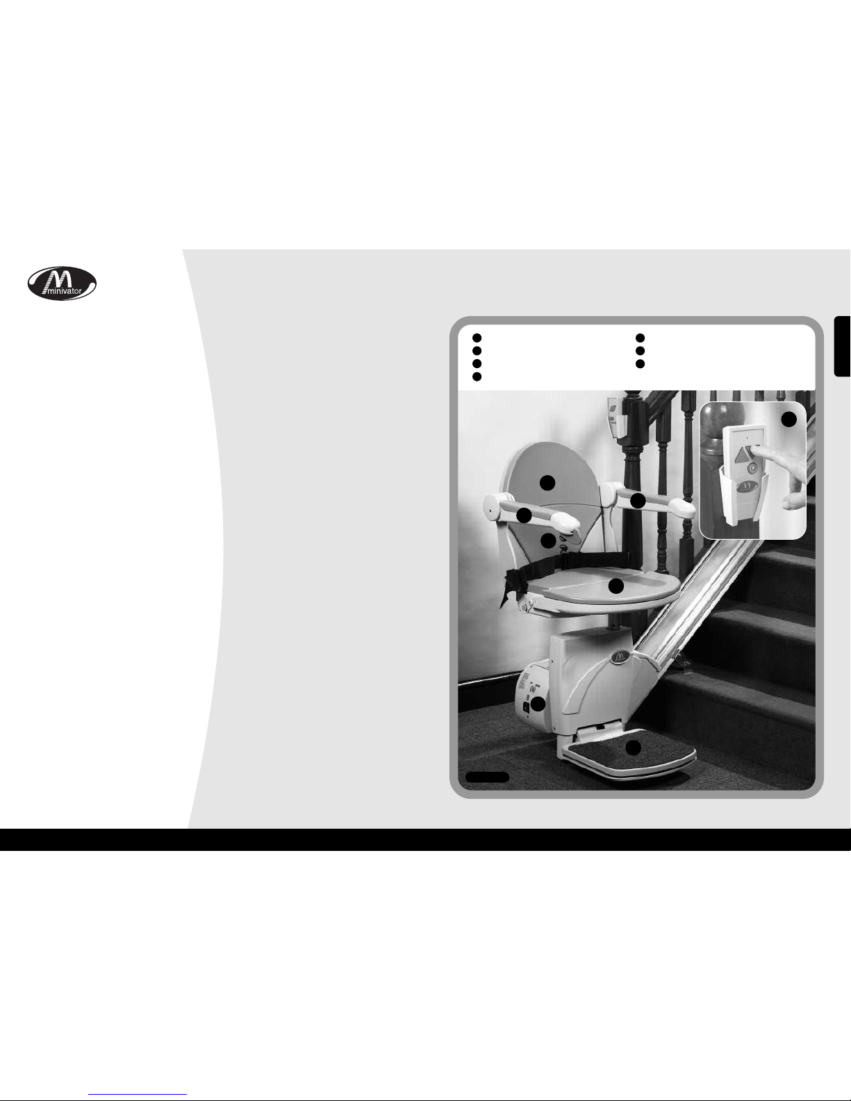
Warnings and precautions
NEVER
Allow more than one person to use the stairlift at any one time.
The maximum carrying capacity is 120kg (19 Stone / 265lb).
NEVER
Allow children to play on or with the stairlift.
NEVER
Allow water to come into contact with the components in the stairlift. If you have to
transport liquids DO SO WITH CARE.
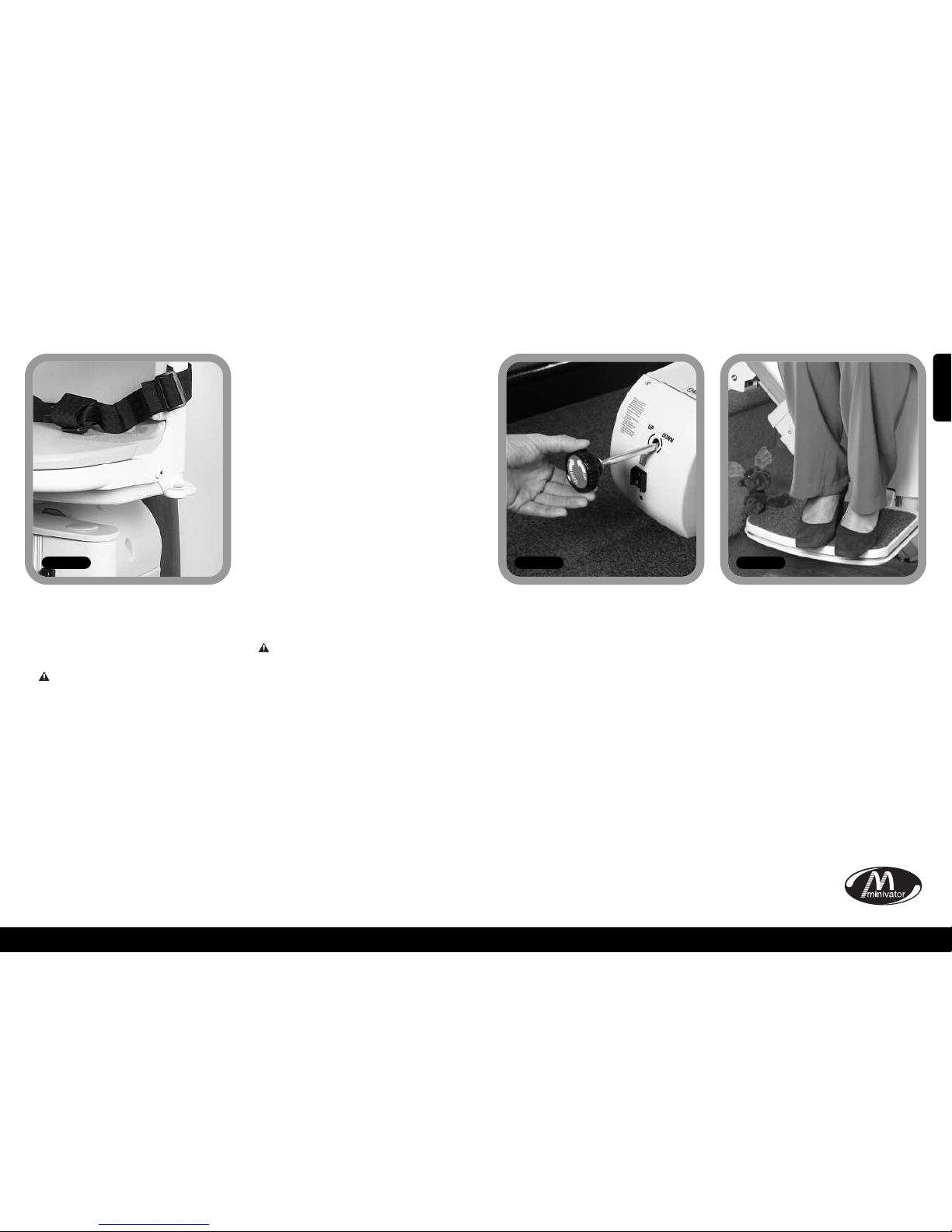
NEVER
Place objects in the track or leave objects on the stairs, where they could come into contact
with the lift in operation. Your stairlift is fitted with pressure sensitive side edges and
undertray on the footplate, which will automatically stop the lift if it detects any
obstructions.
NEVER
Use the stairlift without using the lap belt, or any other safety belts or harnesses fitted.
NEVER
Use the stairlift in a standing position.
ALWAYS
Keep your FEET ON THE FOOTPLATE whilst the stairlift is in motion, and try to avoid your
feet hanging over the edges of the footplate.
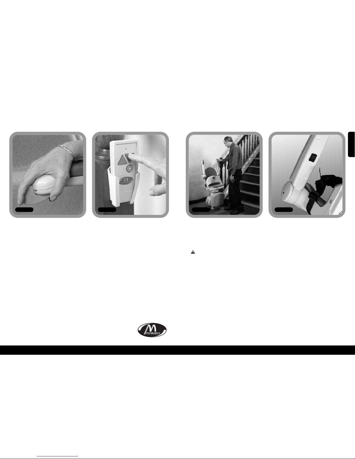
NEVER
Swivel the seat until the lift has come to a stop at the top or bottom of the staircase.
ALWAYS
Fold the chair when it is not in use to avoid obstructing exits.
WARNING
If the overspeed governor is activated it should only be reset by a competent person, i.e. a
Minivator approved dealer. Activation of the overspeed governor is indicated by the lift not
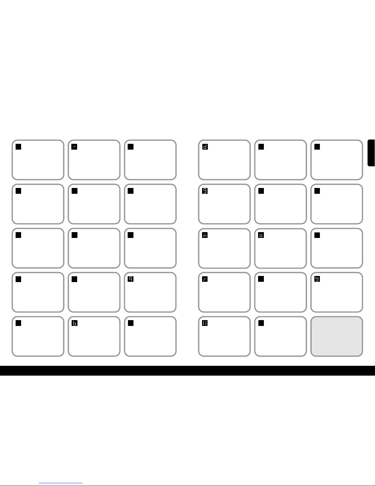
being able to be driven down the stairs and the diagnostic display showing 0.
xRoutine are and maintenan ex
Battery care
and charging
Your Minivator stairlift is battery powered
and will continue to work for a period of
time even if you have a power cut. You
should normally be able to travel up and
down the stairs at least 10 times without
needing to charge the batteries.
Particularly in the event of a power cut,
however you should always ensure that
there is sufficient light to allow safe travel,
and especially at each end of the track
where you get on and off the lift.
Your stairlift track is fitted with charging
points, normally at the top and bottom of
the staircase. Your stairlift should be left on
one of these charging points when not in
use to ensure that the batteries are
charged. If the stairlift makes a beeping
noise and/or the display show a "2" when
it is left on a charging point and it is not in
use IT IS NOT CHARGING. Please check that
the power supply for the stairlift is
switched on. If it is switched on and the
beeping continues please contact your
dealer or the Minivator Service Department
on 08700 118282.
Maintenance
There are no user serviceable parts fitted to
your stairlift. If any damage is visible or
your stairlift sounds or behaves unusually
contact Minivator or your approved dealer
immediately. We advise that your stairlift is
serviced after the first 12 months and
thereafter AT LEAST EVERY 12 MONTHS.
Care and cleaning
Before cleaning any part of your Minivator
stairlift, please ensure you have removed
the key.
The Minivator stairlift is manufactured
from a variety of materials, all with easy
“wipe clean” surfaces. The seat and body
covers can be wiped over with a damp,
NOT WET, cloth and a small quantity of
washing up liquid.
PLEASE DO NOT use abrasive cleaners,
bleach or solvent based cleaners, as these
will damage the seat.
To clean the track, first send the stairlift to
the top of the stairs. The track can be
cleaned with a damp cloth. When most of
the track is clean, move the stairlift to the
bottom of the stairs and finish cleaning the
track making sure that none of the
cleaning debris falls on to it.
To maintain your Minivator stairlift in
good
mechanical order, it is recommended
that
regular services are carried out by qualified
service engineers.
Disposal of
your Stairlift
Your stairlift has been manufactured using
high quality materials and components,
which can be recycled and reused.
The crossed-out wheeled bin
symbol indicates that your
stairlift is covered by the
European Directive 2002/96/EC,
which governs the disposal of
waste electrical and electronic equipment.
This means that your stairlift should not be
disposed of as household waste but should
be appropriately disposed of
for recycling.
Recycling this product will help to protect
the environment by ensuring that all
materials contained in the stairlift are
appropriately handled.
Please contact Minivator on 08700 118282,
your dealer or your local civic office for
further disposal information.
ENGLISH

12
11
11
xAppendix 1 – Diagnosti displayx
Code:
None
Meaning:
No display.
Sel help action:
Press the toggle switch and see if
display comes on. Check that the main
power switch on the lift is turned on. If
this does not clear the fault, contact
your dealer or inivator.
Code:
1Meaning:
Requires charge.
Sel help action:
The stairlift batteries require charging.
Drive the lift to the charge contacts – if
the 'Okay’ code does not show contact
your dealer or inivator.
Code:
Okay Meaning:
Okay.
Sel help action:
Contact your dealer or inivator.
Code:
0Meaning:
Final limit activated
or cable short circuit.
Sel help action:
Check that the keyswitch is on and
seat is fully swivelled to the drive
position. If this does not clear the fault,
contact your dealer or inivator.
0
1
Code:
4Meaning:
Safety edge (up/down
direction) activated –
footplate.
Sel help action:
Contact your dealer or inivator.
4Code:
5Meaning:
Ends limit activated.
Sel help action:
Contact your dealer or inivator.
5
Code:
7Meaning:
Batteries approaching
critical level.
Sel help action:
The stairlift batteries require charging.
Drive the lift to the charge contacts -
if the ’Okay’ code does not show
contact your dealer or inivator.
7Code:
9Meaning:
Shows when toggle
switch is activated in
down/up direction.
Sel help action:
N/A.
Code:
6Meaning:
Safety edge (up/down
direction) activated –
footplate.
Sel help action:
Contact your dealer or inivator.
6
Code:
2
Meaning:
Off charge.
Sel help action:
The stairlift is not parked on a charging position or is
not charging. Drive the lift to the charge contacts – if
the 'Okay’ code does not show or the lift is already on
the charge contacts check the power supply is on.
Failing this contact your dealer or inivator
.
Code:
3Meaning:
Ends limit activated.
Sel help action:
Contact your dealer or inivator.
23
Code:
AMeaning:
Hinge open.
Sel help action:
Contact your dealer or inivator.
Code:
8Meaning:
Shows when toggle
switch is activated in
up/down direction.
Sel help action:
N/A.
8
ACode:
bMeaning:
A switch is active at
power on i.e. Toggle
Up, Toggle Down, IR
Up, IR Down or Learn.
Sel help action:
Contact your dealer or inivator.
Code:
CMeaning:
The IR address
(dip switch) does not
match.
Sel help action:
Contact your dealer or inivator.
C
12
Code:
dMeaning:
The main power relay
is welded closed.
Sel help action:
Contact your dealer or inivator.
Code:
EMeaning:
The main power relay
did not close.
Sel help action:
Contact your dealer or inivator.
E
Code:
FMeaning:
Brake semi-conductor
failed.
Sel help action:
Contact your dealer or inivator.
f
Code:
gMeaning:
Brake not connected.
Sel help action:
Contact your dealer or inivator.
Code:
HMeaning:
The main power relay
has closed early.
Sel help action:
Contact your dealer or inivator.
H
Code:
LMeaning:
Current limit
exceeded.
Sel help action:
Contact your dealer or inivator.
l
Code:
nMeaning:
Half speed.
Sel help action:
If permanently showing contact your
dealer or inivator.
Code:
oMeaning:
The main control
board has a memory
problem.
Sel help action:
Contact your dealer or inivator.
Code:
PMeaning:
Powered swivel did
not respond.
Sel help action:
Contact your dealer or inivator.
P
Code:
rMeaning:
No charge current.
Sel help action:
ake sure that power supply is
switched on from mains. If it is contact
your dealer or inivator.
Code:
N/A Meaning:
Over current.
Sel help action:
Contact your dealer or inivator.
Code:
N/A Meaning:
Lift is in "sleep
mode" to conserve
battery power.
Sel help action:
Press toggle or handset button to
wake lift.
Code:
UMeaning:
Faulty power supply.
Sel help action:
Contact your dealer or inivator.
u
Code:
YMeaning:
The main control
board has a software
fault.
Sel help action:
Contact your dealer or inivator.
NOTE: I the display is
showing anything but the
diagnostic codes listed it
requires resetting.
Drive the lift off the charge
contacts. Turn the main switch on
the unit off for 10 seconds and
then back on.
.8.
ENGLISH

14
13
xAppendix 2 – Wiring diagramsxxAppendix 2 – Wiring diagramsx
CHASSIS BOTTOM EDGE
CHASSIS UNDERPAN
FOOTREST
BOTTOM EDGE
FOOTREST TOP EDGE
FOOTREST UNDER
PAN SAFE EDGE
FOOTPLATE TO
CHASSIS CONNECTOR
CHASSIS TOP EDGE
SEAT TO CHASSIS
CONNECTOR
TO SEAT CONNECTOR
TO
FINAL
LIMIT
M
F
M
F
F
CONVERSION
LOOM
TRACK
OVERRUN
HINGE/PLATFORM
COMMS DATA
CONTACT
POWER SWIVEL
CONNECTION
(POWERED OPTIONS ONLY)
OSG
F
F
M
M
F
M
F
TRACK
BOTTOM LIMIT
TRACK
TOP LIMIT
TO
CONVERSION
LOOM
SW5
SW1
SW6
SW14
WHITE
WHITE
GREY
SPADE
SPADE
SPADE
BULLET
BULLET
RING
TERMINAL
CONNECTOR
9WAYCONNECTOR 8 WAYCONNECTOR
SPADE
WHITE
YELL TAG
YELL TAG
SW13
SW8
VIOLET
VIEW FROM
CABLE SIDE
SW7
SW2
SW3 SW4
BROWN
BROWN
RED
TAG
BLUE
TAG
BLUE
TAG
RED
TAG
BLACK
BLUE
SW10
SW9
RED RED
RED
BROWN
BROWN
VIOLET
VIOLET
VIOLET VIOLET
VIOLET
VIOLET
RED BROWN
GREY
VIOLET
GREY
VIOLET LOOP
GREY
CABLE
SPLICE
CABLE
SPLICE
SEE R/H
CIRCUIT
SEE R/H
CIRCUIT
BROWNBROWN
ORANGE
GREEN
BLUE
GREEN
ORANGE
WHITE
WHITE
DOWN DIRECTION GREEN
3 WAY
CONN
3 WAY
CONN
INFRARED
SENSORS
3 WAY
CONN
TOGGLE COMMON BLUE
UP DIRECTION ORANGE
CHASSIS TOP SAFE-EDGE BROWN
SAFE-EDGE COMMON GREY
CHASSIS BOTT SAFE EDGE VIOLET
BOTT-END LIMIT BLACK
TOP-END LIMIT BLUE
TOP-END LIMIT BLUE
FINAL LIMIT WHITE
1
1
1
2
3
4
5
6
1
1 2 3
4 5 6
2
3
4
5
6
2
21
1
1
1
2
3
1
1
1
2
3
4
5
6
7
8
1
1
1
2
3
2
+
5A
SHIELDED CABLE
DIAGNOSTIC
DISPLAY
BK +
+
+
+
–
–
–
–
–
BK
BATT
BATT
BATT
BATT
BATT
BATT
BATT
RED
M2 MOTOR
M1 MOTOR
IR-1
IR-2
HINGE FUSED
HINGE DATA
DIAG
CHRG
CON-1
CON-1
CON-1
CON-2
CON-2
CON-2
CON-3
CON-3
CON-3
CON-3
CON-3
CON-3
CON-3
2
3
4
5
6
7
8
2
3
4
5
6
7
8
9
2
21
1
2
21
1
2
21
1
1
1
1 1 1 1 1 1
2
2
2
21
1
CHARGE POSITIVE
INPUT VOLTAGE
CHARGE NEGATIVE
THROUGH CHASSIS
MOTOR
BRAKE
15A
QUICKBLOW
FUSE
+24V
POWER FOOTPLATE
POWER SUPPLY
BATTERY
ISOLATION
BATTERY
PACK
DISCONNECT
BLACK
BLACK
SW16
WHITE
BLACK
RED
RED
SPADE
BK2
BK1
2
M+
M–
1 2
1
1
M F PUSH-ON CONNECTOR
KEY:
= MULTI-PIN CONNECTOR
ALL SAFETY CIRCUITS SHOULD BE
NORMALLY CLOSED
FUNCTION OF DIP SWITCHES
ON SMT PCB
DIP 1
HALF SPEED UP
HALF SPEED DN
PING DISABLE
AUTO PLAT DISABLE
AUTO HINGE DISABLE
STANDARD
SLOW RAMP
UNUSED
ON
12 3 4
DIP 2
FULL SPEED UP
FULL SPEED DN
PING ENABLE
AUTO PLAT ENABLE
AUTO HINGE ENABLE
FAST RAMP
UNUSED
ON
12 3 4
1 1
1
2
3
4
5
6
1
2
3
4
5
6
COMMON
CHASSIS BOTTOM EDGE
CHASSIS UNDERPAN
FOOTPLATE TO
CHASSIS CONNECTOR
CHASSIS TOP EDGE
SEAT TO CHASSIS
CONNECTOR
TO SEAT CONNECTOR
TO
FINAL
LIMIT
M
F
M
F
F
CONVERSION
LOOM
TRACK
OVERRUN
HINGE/PLATFORM
COMMS DATA
CONTACT
POWER SWIVEL
CONNECTION
(POWERED OPTIONS ONLY)
OSG
F
F
M
M
F
M
F
TRACK
BOTTOM LIMIT
TRACK
TOP LIMIT
TO
CONVERSION
LOOM
SW5
SW1
SW6
SW14
WHITE
WHITE
GREY
SPADE
SPADE
SPADE
BULLET
BULLET
RING
TERMINAL
CONNECTOR
9WAYCONNECTOR 8 WAYCONNECTOR
SPADE
WHITE
YELL TAG
YELL TAG
CSE1
SW13
SW8
VIOLET
VIEW FROM
CABLE SIDE
SW7
SW2
SW3 SW4
BROWN
BROWN
BROWN
BROWN
RED
TAG
BLUE
TAG
BLUE
TAG
RED
TAG
BLACK
BLUE
SW10
SW9
RED RED
RED
BROWN
VIOLET
VIOLET
VIOLET
VIOLET
VIOLET
RED
BROWN BROWN
GREY
VIOLET
GREY
BROWN LOOP GREY
CABLE
SPLICE
CABLE
SPLICE
SEE L/H
CIRCUIT
SEE L/H
CIRCUIT
BROWN
ORANGE
ORANGE
BLUE
GREEN
GREEN
WHITE
WHITE
DOWN DIRECTION GREEN
3 WAY
CONN
3 WAY
CONN
INFRARED
SENSORS
3 WAY
CONN
TOGGLE COMMON BLUE
UP DIRECTION ORANGE
CHASSIS TOP SAFE-EDGE BROWN
SAFE-EDGE COMMON GREY
CHASSIS BOTT SAFE EDGE VIOLET
BOTT-END LIMIT BLACK
TOP-END LIMIT BLUE
TOP-END LIMIT BLUE
FINAL LIMIT WHITE
1
1
1
2
3
4
5
6
1
1 2 3
4 5 6
2
3
4
5
6
2
21
1
1
1
2
3
1
1
1
2
3
4
5
6
7
8
1
11
2
3
2
+
5A
SHIELDED CABLE
DIAGNOSTIC
DISPLAY
BK +
+
+
+
–
–
–
–
–
BK
BATT
BATT
BATT
BATT
BATT
BATT
BATT
RED
M2 MOTOR
M1 MOTOR
IR-1
IR-2
HINGE FUSED
HINGE DATA
DIAG
CHRG
CON-1
CON-1
CON-1
CON-2
CON-2
CON-2
CON-3
CON-3
CON-3
CON-3
CON-3
CON-3
CON-3
2
3
4
5
6
7
8
2
3
4
5
6
7
8
9
2
21
1
2
21
1
2
21
1
1
1
11 1 1 1
1
2
2
2
21
1MOTOR
BRAKE
15A
QUICKBLOW
FUSE
+24V
POWER FOOTPLATE
POWER SUPPLY
BATTERY
ISOLATION
BATTERY
PACK
DISCONNECT
BLACK
BLACK
SW16
WHITE
BLACK
RED
RED
SPADE
BK2
BK1
2
M+
M–
1 2
1
1
FOOTREST
TOP EDGE
FOOTREST BOTTOM EDGE
FOOTREST UNDER
PAN SAFE EDGE
CHARGE POSITIVE
INPUT VOLTAGE
CHARGE NEGATIVE
THROUGH CHASSIS
M F PUSH-ON CONNECTOR
KEY:
= MULTI-PIN CONNECTOR
ALL SAFETY CIRCUITS SHOULD BE
NORMALLY CLOSED
FUNCTION OF DIP SWITCHES
ON SMT PCB
DIP 1
HALF SPEED UP
HALF SPEED DN
PING DISABLE
AUTO PLAT DISABLE
AUTO HINGE DISABLE
STANDARD
SLOW RAMP
UNUSED
ON
12 3 4
DIP 2
FULL SPEED UP
FULL SPEED DN
PING ENABLE
AUTO PLAT ENABLE
AUTO HINGE ENABLE
FAST RAMP
UNUSED
ON
12 3 4
1 1
1
2
3
4
5
6
1
2
3
4
5
6
COMMON
Simpli ity+blo k s hemati – left hand stairlift
Simpli ity+blo k s hemati – right hand stairlift
ENGLISH
ENGLISH

15
xAppendix 2 –Wiring diagramsx
16
15
INFRARED/RADIO
LEARN BUTTON
NO CONNECTION
REQUIRED
BRAKE CONNECTOR
CHARGE +
BATTERY POSITIVE
BATTERY NEGATIVE
MOTOR 1 (BLACK)
MOTOR 2 (WHITE)
+24V FUSED
HINGE DATA (GREY CABLE)
NO CONNECTION REQUIRED
DIP SWITCH 1
5A
QUICK BLOW
DIP SWITCH 2
NO CONNECTION REQUIRED
7 SEGMENT DISPLAY
NO CONNECTION
REQUIRED 9 WAY CONNECTOR
ON
ON
1 2 3 4
1 2 3 4
8 WAY CONNECTOR
INFRARED/RADIO
IF ANY DIP SWITCHES ARE CHANGED, PLEASE TURN OFF LIFT,
WAIT 10 SECONDS, THEN POWER THE LIFT BACK ON.
DIP 1
ON
12 3 4
DIP 2
ON
12 3 4
KEY:
DIP SWITCH SETTING CSE126 (POWER SWIVEL BOARD)
THIS SETTING WILL ENABLE POWER SWIVEL MODE
ON
12 3 4
HALF SPEED UP
HALF SPEED DOWN
PING DISABLE
PLATFORMDISABLE
HINGE DISBLE
LEFT HAND LIFT
SLOW RAMP
UNUSED
FULL SPEED UP
FULL SPEED DOWN
PING ENABLE
PLATFORM ENABLE
HINGE ENABLE
RIGHT HAND LIFT
FAST RAMP
UNUSED
xAppendix 3 – Certifi ate of Conformityx
We
Minivator Ltd
of
82 First Avenue
Pensnett Estate
Kingswinford
West Midlands
DY6 7FJ, England.
Declare under our sole responsibility that the product
Minivator Simplicity+950 Stairlift
has been manufactured in conformity with the following
standards and specification:
BS5776:1996 Powered Stairlifts
ISO 9386-2 2000-11-01
To which this declaration relates is in conformity with the following
national standards:
Electro Magnetic Compati ility Directive 89/336/EEC
Low Voltage Directive – 73/23/EEC
Machinery Directive – 98/37/EEC
Signed:
Name: G. Wel h
Date:
Position: Engineering Manager
Simpli ity+Left Hand and Right Hand Standard
ENGLISH

17
Important information about your stairlift whi h
should be ompleted by the installation engineer.
Installed by: (Company Name)
Serial No
Date of installation
First servi e due
Dealer Stamp
18
ENGLISH

Vielen Dank, dass Sie sich für unseren
Minivator Treppenlift entschieden haben.
Bitte lesen Sie sie diese Gebrauchsanleitung
sorgfältig durch. Ihr Minivator Treppenlift
ist ein Präzisionsgerät, dass für Sie sorgfältig
entworfen und gebaut wurde. Damit Sie
viele Jahre Ihr Produkt ohne Störungen und
Schwierigkeiten nutzen können, sollten Sie
die Anleitungen bezüglich der Wartung und
der Sicherheit mit besonderer Sorgfalt lesen
und beachten. Minivator empfiehlt, dass Sie
nur die in diesem Handbuch aufgeführten
Routinewartungsarbeiten und die Reinigung
selbst ausführen und die grundlegende Wartung
einem qualifizierten Techniker überlassen.
Bitte setzen Sie sich mit Ihrem Minivator
Händler oder unserer Kundendienstabteilung
unter der Telefonnummer 08700 118282 in
Verbindung, wenn Ihr Treppenlift gewartet
werden muss. Wir helfen Ihnen gerne weiter.
Britis he
Standardnormen
Minivator unterliegt dem internationalen
Standard für Industrienormen der durch das
ISO 9001 Prüfsiegel beglaubigt und
zugelassen ist.
Alle Minivator Treppenlifte werden gemäß
der Britischen Standards für Treppenlifte
(BS5776) :1996 und ISO 9386-2 gebaut und
getestet. Sie tragen auch das CE Prüfsiegel.
Minivator Produkte werden fortwährend
auf dem ISO 9001 Standard geprüft und
Sie können sicher sein, dass sie stets ein
qualitativ hochwertiges und
zuverlässiges Produkt benutzen.
Einführung 19
Britische Normen 19
Ausstattung Ihres 20
Minivator Simplicity+950
Betrie Ihres 21
Minivator Simplicity+950
S hlüssels halter 21
Ein/Aus S halter 21
Prüfanzeige 22
Vor der Inbetriebnahme 22
Steuerhebel 23
Fernsteuerung 23
Treppenlift zusammenklappen 24
Handhabung des Drehsitzes 25
Anleitung für den Gebrau h
der Notfallkurbel 26
Hindernisse 26
Sicherheit und Kundendienst
27
Hinweise und Vorsi htsmaßnahmen 27
Routinewartung und
Reinigung 28
Batteriewartung und Laden 28
Wartung und Reinigung 28
Entsorgung Ihres Treppenlifts 28
Anhang 1 29
– Prüfanzeige
Anhang 2 31
– S haltpläne
Anhang 3 34
Te hnis hes Guta hten
19
Einführung
20
Seite
1
2
3
4
6
6
7
A . 1
Ausstattung Ihres Minivator Simpli ity+950
Einfach zu handha ender
Schlüsselschalter
Klapp are Armstützen
Prüfanzeige
5
6
7
Klappsitz
Drehsitz
Infrarot-Fernsteuerung
Klapp are Fußstütze mit
Sicherheitskanten
4
3
2
1
5
DEUTSCH

Betrieb Ihres Minivator Simpli ity+950
Ihr Minivator Treppenlift ist mit einem
Schlüsselschalter ausgestattet (Abb.2).
Der Treppenlift kann erst benutzt werden,
wenn der Schlüssel eingesteckt und zur
Einschaltposition gedreht wurde.
Der Schlüsselschalter dient dem weck,
dass Sie Ihren Treppenlift gegen
unbefugte Benutzung (z.B. durch
Kinder) absperren können.
Der eingesteckte Schlüssel kann auch auf
der Einschaltposition stehen bleiben.
Wenn Sie Ihren Schlüssel aus
Sicherheitsgründen abziehen, legen Sie
ihn bitte an einen sicheren Ort.
Wenn der Schlüsselschalter ausgeschaltet
ist, lädt der Lift weiter.
Ihr Treppenlift ist mit einem Schlüsselschalter
und mit einem Ein/Aus Schalter (Abb.3) auf
der Unterseite des Liftes ausgestattet.
Versichern Sie sich, dass der Schalter auf
„EIN“ steht. Die Fehlerprüfanzeige
leuchtet auf, wenn dies angezeigt wird.
Wenn Sie für längere eit aus dem Haus
gehen und die Hauptstromversorgung
abschalten, ist es wichtig, dass Sie den Lift
mit dem Hauptschalter ausschalten.
Auf diese Art bleiben die Liftbatterien
geladen.
Vor der In etrie nahme
Bevor Sie Ihren Treppenlift in Betrieb
nehmen, vergewissern Sie sich, dass die
Treppen frei von anderen Personen,
Haustieren oder Objekten sind, die den
Treppenlift behindern.
Vergewissern Sie sich, dass die Armlehnen,
die Fußstütze und der Sitz zur Benutzung
aus Sicherheitsgründen heruntergeklappt
sind. (Abb. 5).
VOR DER BENUTZUNG DES
TREPPENLIFTES IMMER DEN
BECKENGURT ANLEGEN.
22
Schlüsselschalter Ein/Aus Schalter
21
A . 2 A . 3 A . 4 A . 5
Prüfanzeige
Der Treppenlift ist mit einer Prüfanzeige
(Abb. 4) ausgestattet, die einen Code zur
Fehlersuche und –analyse anzeigt. Schlagen
Sie unter Anhang 1 für die Erklärungen der
Prüfcodes nach. Wenn Sie ein problem bei
Ihrem Lift bemerken, schauen Sie auf die
Anzeige und notieren Sie die angezeigten
Codes. Melden Sie Ihrem Kundendienst
diese Codenummern bei der Fehlermeldung.
DEUTSCH

24
23
Betrieb Ihres Minivator Simpli ity+950
Steuerhe el
A . 6
Mit der Fernbedienung (Abb. 7) kann der
Lift an der Treppen von oben/unten geholt
werden oder eine vorhandene
automatische Klappschiene gesteuert
werden. Mit der Fernbedienung kann auch
eine Pflegeperson anstatt des Benutzers
den Lift bedienen.
Die Pflegeperson sollte solange nicht auf
der Treppe sein, is der Lift zum Stillstand
gekommen ist.
Ihr Sitz, Armlehnen und die Fußstütze
Ihres Minivator Simplicity+ 950 sind
klappbar um bei parkiertem Treppenlift
weiterhin leicht die Treppe nutzen zu
können (Abb. 8).
SICHERHEITSMASSNAHME!
DEN TREPPENLIFT STETS IN DIE
PARKIERUNGSPOSITION BRINGEN. D.H. MIT
USAMMENGEKLAPPTEN ARMLEHNEN,
SIT UND FUSSTÜT EN UND DEM SIT
PARALLELL UR SCHIENE GEDREHT WIE
AUF ABBILDUNG 8, SODASS KEINE WEGE
BLOCKIERT WERDEN.
Manuelle Fußstütze Anschluß
(wahlweise)
Wenn Ihr Treppenlift mit einer manuellen
Fußstütze ausgestattet ist, klappt die
Fußstütze automatisch weg, wenn die
Sitzrückenlehne angehoben wird. Beim
Absenken der Sitzrückenlehne wird auch
die Fußstütze ausgeklappt.
Fußstützenautomatik – an der
Sitzrückenlehne (wahlweise)
Wenn Ihr Treppenlift mit einer
Fußstützenautomatik an der Sitzlehne
ausgestattet ist, klappt die Fußstütze
automatisch weg, wenn die
Sitzrückenlehne angehoben wird. Beim
Absenken der Sitzrückenlehne wird auch
die Fußstütze ausgeklappt.
Fußstützenautomatik – an der
Armlehne (wahlweise)
Wenn Ihr Treppenlift mit einer
Fußstützenautomatik mit einem Schalter
an der Armlehne ausgestattet ist (Abb. 9),
wird die Fußstütze mit dem Betätigen des
Schalter unter der Armlehne abgesenkt.
um usammenklappen der Fußstütze den
Schalter in die andere Richtung legen.
NB Wenn die Fußstütze angehoben/gesenkt
wird während Sie auf dem Treppenlift
sitzen, dürfen Ihre Füße der Platte nicht im
Weg sein.
Fernsteuerung
Treppenlift parkieren
A . 7 A . 8
Ihr Minivator Treppenlift fährt durch ein
einfaches Drücken und Halten des
Steuerhebels in die gewünschten Richtung
(Abb. 6). Der Treppenlift stoppt
automatisch wenn der Hebel während der
Fahrt losgelassen und braucht 1 Sekunde
Verzögerung bevor der Lift die Fahrt
fortsetzt.
BITTE BEACHTEN:
Aus Sicherheitsgründen verzögert der
Treppenlift das Losfahren um 1 Sekunde
nachdem der Steuerhebel gedrückt und
gehalten wird, um einen unbeabsichtigten
Betrieb zu vermeiden. Der Treppenlift
stoppt automatisch wenn der Hebel
während der Fahrt losgelassen und braucht
1 Sekunde Verzögerung bevor der Lift die
Fahrt fortsetzt.
Bei Richtungswechsel während der Fahrt
beträgt die Verzögerung des Liftes 3
Sekunden.
A . 9

26
25
Betrieb Ihres Minivator Simpli ity+950
Ge rauch des
Steuerhe els
A . 10
Ein Drehsitz ermöglicht es Ihnen, leichter
oben oder unten an der Treppe
auszusteigen, indem Sie sich zum
Treppenabsatz hin drehen können.
Den Drehsitz erst in Gang setzen, wenn
der Lift abgestoppt hat.
um Drehen des Sitzes entweder einen der
beiden Drehhebel (auf beiden Seiten
angebracht) herunterdrücken oder -
ziehen. Das löst die Sitzsperre und der Sitz
kann von der Fußstütze weg gedreht
werden. Wenn der Sitz 90° erreicht hat,
rastet er wieder in die Position ein.
Der Sitz sollte erst verlassen werden, wenn
der Sitz fest „eingeklickt“ d.h. eingerastet
ist.
Um in die andere Richtung zu drehen, den
Vorgang wiederholen und vom
Treppenabsatz wegdrehen.
Drehstuhl Automatik (Wahlweiss)
Wenn Ihr Treppenlift wahlweise mit einem
Automatikdrehstuhl ausgerüstet ist, hat
dieser keine Hebel. Um den Sitz zu drehen,
den Hebel aufwärts halten. Wenn der
Treppenlift oben an der Treppe
angekommen ist, den Hebel in dieser
Position lassen.
Der Treppenlift piepst dreimal und der Sitz
dreht sich. Wenn der Sitz sich um 90°
gedreht hat, stoppt er ab. Verlassen Sie den
Sitz erst, wenn er voll gedreht hat.
Um in die entgegengesetzte Richtung zu
drehen, den Vorgang genauso
wiederholen. Den Hebel nach unten legen.
Der Sitz piepst dreimal und dreht nach
einer kurzen Pause in die Fahrtrichtung .
Halten Sie den Hebel weiter nach unten.
Der Treppenlift piepst erneut dreimal
bevor er herunterfährt.
!SICHERHEITSHINWEISE
NIEMALS
Den Sitz ohne Sitzgurt drehen.
NIEMALS
Ohne Einrastung den Drehsitz verlassen
oder benutzen.
NIEMALS
Den Drehsitz betätigen, währen der
Treppenlift in Bewegung ist.
(Sicherheitshalber stoppt der Lift ab, sobald
Sie versuchen den Drehmechanismus
auszulösen).
NIEMALS
Nach unten oder hochfahren, solange der
Sitz nicht in der korrekten Position ist (d.h.
in Richtung quer über der Treppe).
Betrieb Ihres Minivator Simpli ity+950
Im unwahrscheinlichen Fall eines
Stromausfalls des Liftes oder eines
Festhängens des Antriebs oben gibt es
eine Nothandkurbel. Befolgen Sie die
Schritte:
1. Den Treppenlift mit dem Schlüssel
abschalten.
2. Die Nothandkurbel einsetzen (Abb. 11).
3. Drehen Sie die Kurbel in der benötigten
Richtung.
4. Wenn die gewünschte Position erreicht
ist, die Nothandkurbel entfernen und
den Lift anschalten.
Falls Sie Fragen dazu haben, setzen Sie sich
mit dem örtlichen Minivator Händler unter
der Telefonnummer 08700 118282 in
Verbindung.
Ihr Treppenlift ist mit Sicherheitskanten an
der Unterseite des Fußbrettes und am Lift
selbst ausgestattet, die den Treppenlift
anhalten wenn ein Gegenstand sich im
Fußbrett verfängt (Abb. 12).
Um den Gegenstand zu entfernen, den
Treppenlift ein Stück rückwärts weg vom
O jekt ewegen und es von der Treppe
nehmen lassen. Dann die Fahrt mit dem
Lift fortsetzen.
Nothandkur el
Hindernisse
A . 11 A . 12
DEUTSCH

28
27
xSi herheit und Kundendienstx
Wir empfehlen einen Kundendienstcheck des Liftes nach den ersten 12 Monaten und danach
MINDESTENS ALLE 12 MONATE.
Diese Arbeit sollte von einer dafür qualifizierten Person durchgeführt werden, d.h. einem
anerkannten Minivator Händler.
Wenn Sie dazu Fragen haben, den Minivator-Kundendienst unter der Telefonnummer
08700 118282 anrufen.
Wenn Sie den Treppenlift gekauft haben und ihn nicht mehr benötigen, setzen Sie sich mit Ihrem
Händler oder Minivator in Verbindung. Evtl. kann der Lift weiterverkauft werden.
Hinweise und Sicherheit
NIE
Mehr als eine Person zu selben eit den Treppenlift benutzen lassen.
Die maximale Tragkraft beträgt 120kg.
NIE
Kindern erlauben mit oder auf dem Treppenlift zu spielen.
NIE
Die Teile des Treppenlifts nicht mit Wasser in Berührung bringen. Flüssigkeiten VORSICHTIG
damit transportieren.
NIE
Gegenstände auf der Schiene oder auf der Treppe lassen, wo sie mit dem Lift in Berührung
kommen können. Ihr Treppenlift ist mit druckempfindlichen Seitenkanten am Lift und an
der Unterseite des Fußbrettes ausgerüstet, die den Lift automatisch stoppen wenn sie ein
Hindernis orten.
NIE
Den Treppenlift ohne den Sicherheitsgurt, oder den Beckengurt nutzen.
NIE
Den Treppenlift stehend benutzen.
IMMER
Die Füße während der Fahrt AUF DEM FUSSBRETT BEHALTEN und nicht die Füße über das
Fußbrett hinaus hängen lassen.
NIE
Den Sitz drehen bevor der Lift oben oder unten an der Treppe abgestoppt hat.
IMMER
Den Stuhl zusammenklappen wenn er nicht in Gebrauch ist (sonst Hindernis).
WARNUNG
Wenn der Geschwindigkeitsbegrenzer aktiviert wurde, sollte er nur von einer qualifizierten
Person zurückgesetzt werden. Dieser Fall wird dadurch angezeigt, dass der Lift nicht die
Treppe hinunterfährt und die Prüfanzeige die iffer 0 anzeigt.
xRoutine he ks und Wartungx
Batteriepflege und
Aufladen
Ihr Minivator Treppenlift ist
batteriebetrieben und kann auch nach einem
Stromausfall eine eitlang funktionieren. Im
Normalfall können Sie etwa 10 Mal fahren
bevor die Batterien geladen werden müssen.
Im Falle eines Stromausfalls bitte darauf
achten, dass genügend Licht vorhanden ist,
um besonders oben und unten an der Treppe
einen sicheren Ausstieg/Einstieg zu
gewährleisten.
Ihre Treppenliftschiene ist mit zwei
Ladepunkten ausgestattet – oben und unten
an der Treppe. Der Treppenlift muss bei
Nichtbenutzung an einer dieser Stellen
parkiert werden, um aufzuladen. Wenn er
ein Piepgeräusch macht und /oder eine „2“
auf der Prüfanzeige anzeigt und er nicht in
Betrieb ist LÄDT ER NICHT AUF. Bitte
überprüfen, ob die Stromversorgung für den
Treppenlift eingeschaltet ist. Wenn er
eingeschaltet ist und der Piepton nicht
aufhört, bitte Ihren Minivator Händler oder
den Kundendienst unter der Nummer 08700
118282 anrufen.
Reparaturen
Ihr Treppenlift hat keine für den Nutzer
verwertbaren Teile. Wenn Beschädigungen
sichtbar sind oder das Gerät ungewohnte
Geräusche hervorbringt oder Störungen im
Betrieb zeigt, bitte Ihren Händler oder
Minivator verständigen. Wir empfehlen
einen Kundendienstcheck des Liftes nach den
ersten 12 Monaten und danach MINDESTENS
ALLE 12 MONATE.
Pflege & Wartung
Bevor Sie Ihren Minivator Treppenlift
reinigen, bitte vorher den Schlüssel abziehen.
Ihr Minivator Treppenlift ist mit
verschiedenen, leicht zu reinigenden
Materialien gebaut worden. Der Sitz und die
Verkleidungen können mit einem feuchten,
ABER NICHT NASSEN, Tuch und etwas
Reinigungsmittel abgewischt werden.
Bitte KEINE Scheuermittel, Bleiche oder
lösungsmittelhaltige Reiniger benutzen,
denn diese beschädigen den Sitz.
Für die Schienenreinigung, den Treppenlift
zum oberen Haltepunkt fahren. Die Schiene
kann mit einem feuchten Tuch abgewischt
werden. Wenn die Schiene dort sauber ist,
den Treppenlift nach unten fahren und die
Schiene reinigen. Dabei sollten keine
Schmutzpartikel in die Schiene fallen.
Damit Ihr Minivator Treppenlift im
einwandfreien technischen ustand bleibt,
empfehlen wir eine regelmäßige Wartung
durch qualifizierte Techniker.
Entsorgung Ihres
Treppenlifts
Ihr Treppenlift besteht aus hochwertigen
Materialien und Komponenten, die
wiederverwendet werden können.
Das Symbol des durchgestrichenen
Mülleimers bedeutet, dass Ihr
Treppenlift unter die europäische
Abfallrichtlinie Nr. 2002/96/EC,
fällt, die die Entsorgung von
Elektroschrott und elektronischen Geräten
regelt.
Ihr Treppenlift darf nicht im
Hausmüll/Sperrmüll entsorgt werden,
sondern muss dem
Wiederverwertungskreislauf zugeführt
werden.
Wenn das Produkt wiederverwertet wird,
schützen Sie damit die Umwelt und sparen
wertvolle Rohstoffe, aus denen Ihr
Treppenlift hergestellt worden ist, ein.
Die Minivator Telefonnummer 08700 118282,
Ihr örtlicher Händler oder Ihre
Stadtverwaltung informieren Sie gerne über
die Entsorgungrichtlinien.
DEUTSCH

12
11
29
xAnhang 1 – Prüfanzeigex
Code:
Kein
Bedeutung:
Keine Anzeige.
Selbsthil emaßnahme:
Den Hebel drücken und versuchen das
Display anzuzeigen. Der Hauptschalter
am Lift muss eingeschaltet sein. Wenn
dies den Fehler nicht behebt Ihren
Händler oder inivator verständigen.
Code:
1Bedeutung:
Laden erforderlich.
Selbsthil emaßnahme:
Die Treppenliftbatterien müssen
aufgeladen werden. Den Lift zu den
Ladepunkten fahren –
Wenn der “Okay” Code nicht angezeigt
wird, Ihren Händler oder inivator anrufen.
Code:
Okay Bedeutung:
Okay.
Selbsthil emaßnahme:
Ihren Händler oder inivator
verständigen.
Code:
0Bedeutung:
Überlastung aktiviert
oder.
Selbsthil emaßnahme:
Überprüfung des Schlüsselschalter und
der korrekten Position des Drehsitzes.
Wenn dies den Fehler nicht behebt Ihren
Händler oder inivator verständigen.
0
1
Code:
4Bedeutung:
Sicherheitskante
(aufwärts/abwärts)
aktiv – Fußbrett.
Selbsthil emaßnahme:
Ihren Händler oder inivator
verständigen.
4Code:
5Bedeutung:
Toleranzgrenze
erreicht.
Selbsthil emaßnahme:
Ihren Händler oder inivator
verständigen.
5
Code:
7Meaning:
Batteries approaching
critical level.
Selbsthil emaßnahme:
Die Treppenliftbatterien müssen aufgeladen
werden. Den Lift zu den Ladepunkten fahren
– Wenn der “Okay” Code nicht angezeigt
wird, Ihren Händler oder inivator anrufen.
7Code:
9Bedeutung:
Anzeige für Hebel
abwärts/aufwärts.
Selbsthil emaßnahme:
N/A.
Code:
6Bedeutung:
Sicherheitskante
(aufwärts/abwärts)
Richtung aktiviert-
Fußsstütze.
Selbsthil emaßnahme:
Ihren Händler oder inivator
verständigen.
6
Code:
2
Bedeutung:
Laden Aus.
Selbsthil emaßnahme:
Der Treppenlift ist nicht auf einem
Ladepunkt oder lädt nicht. Den Lift zu
den Ladepunkten fahren –
Wenn der “Okay” Code nicht angezeigt
wird, Ihren Händler oder inivator anrufen.
Code:
3Bedeutung:
Grenze aktiviert.
Selbsthil emaßnahme:
Ihren Händler oder inivator
verständigen.
23
Code:
ABedeutung:
Klappschiene offen.
Selbsthil emaßnahme:
Ihren Händler oder inivator
verständigen.
Code:
8Bedeutung:
Anzeige für Hebel
abwärts/aufwärts.
Selbsthil emaßnahme:
N/A.
8
ACode:
bBedeutung:
Schalter ist aktiv.
Selbsthil emaßnahme:
Ihren Händler oder inivator
verständigen.
Code:
CBedeutung:
Die IR Adresse
(Wippschalter) passt
nicht.
Selbsthil emaßnahme:
Ihren Händler oder inivator
verständigen.
C
30
Code:
dBedeutung:
Schalter klemmt.
Selbsthil emaßnahme:
Ihren Händler oder inivator
verständigen.
Code:
EBedeutung:
Hauptschalter
schliesst nicht ab.
Selbsthil emaßnahme:
Ihren Händler oder inivator
verständigen.
E
Code:
FBedeutung:
Bremse fällt aus.
Selbsthil emaßnahme:
Ihren Händler oder inivator
verständigen.
f
Code:
gBedeutung:
Bremse nicht
angeschlossen.
Selbsthil emaßnahme:
Ihren Händler oder inivator
verständigen.
Code:
HBedeutung:
Hauptschalter schaltet
zu früh ab.
Selbsthil emaßnahme:
Ihren Händler oder inivator
verständigen.
H
Code:
LMeaning:
Current limit
exceeded.
Selbsthil emaßnahme:
Ihren Händler oder inivator
verständigen.
l
Code:
nBedeutung:
Halbe
Geschwindigkeit.
Selbsthil emaßnahme:
Wenn dauerhaft, Ihren Händler oder
inivator verständigen.
Code:
oBedeutung:
Speicherproblem an der
Hauptsteuerungsplatine.
Selbsthil emaßnahme:
Ihren Händler oder inivator
verständigen.
Code:
PBedeutung:
Automatikhebel
reagiert nicht.
Selbsthil emaßnahme:
Ihren Händler oder inivator
verständigen.
P
Code:
rBedeutung:
Ladestrom.
Selbsthil emaßnahme:
Hauptschalter muss eingeschaltet sein.
Wenn er es ist, bitte Händler oder
inivator verständigen.
Code:
N/A Bedeutung:
Überspannung.
Selbsthil emaßnahme:
Ihren Händler oder inivator
verständigen.
Code:
N/A Bedeutung:
Lift ist im
“Sleepmodus“ um
Batterie zu sparen.
Selbsthil emaßnahme:
Den Hebel drücken oder die
Handkurbel drehen, um den Lift zu
aktivieren.
Code:
UBedeutung:
Stromversorgung
defekt.
Selbsthil emaßnahme:
Ihren Händler oder inivator
verständigen.
u
Code:
YBedeutung:
Die Hauptsteuerungs-
platine hat einen
Softwarefehler.
Selbsthil emaßnahme:
Ihren Händler oder inivator
verständigen.
HINWEIS: Wenn die Anzeige
etwas anderes als die
Prü codes anzeigt, einen
Reset durch ühren.
Den Lift von den Ladepunkten
wegfahren. Den Hauptschalter
etwa für 10 Sekunden ausschalten,
und dann wieder einschalten.
.8.
DEUTSCH

32
31
xAnhang 2 – S haltplänex
Simpli ity+blo k s hemati – Treppenlift re hts
xAnhang 2 – S haltplänex
GEHÄUSE UNTERE KANTE
GEHÄUSE BODEN
FUSSABLAGE UNTERE KANTE
FUSSABLAGE OBERE KANTE
VERBINDUNG FUSSSTÜTZE
ZU GEHÄUSE
GEHÄUSE OBEN KANTE
SITZ AN GEHÄUSE
ANSCHLUSS
ZU SITZ VERBINDUNG
ZU
LIMIT
GRENZE
M
F
M
F
F
UMWANDLUNG
KABELBAUM
SCHIENE
ÜBERSCHUSS
KLAPPSCHIENE/
PLATTFORM
DATENÜBER-
TRAGUNGSKONTAKT
DREHSTUHLAUTOMATIK
ANSCHLUSS
(NUR AUTOMATIK)
OSG
F
F
M
M
F
M
F
SCHIENE UNTERE
GRENZE
SCHIENE OBERE
GRENZE
ZU
UMWANDLUNG
KABELBAUM
SW5
SW1
SW6
SW14
WEIß
WEIß
GRAU
FLACHSTECKER
FLACHSTECKER
FLACHSTECKER
SCHRAUBE
SCHRAUBE
KABELSCHUH
ANSCHLUSS
9 WEGE VERBINDUNG 8 WEGE VERBINDUNG
FLACHSTECKER
WEIß
GELBES
ETIKETT
GELBES
ETIKETT
SW13
SW8
VIOLETT
ANSICHT
KABELSEITE
SW7
SW2
SW3 SW4
BRAUN
BRAUN
ROTES
ETIKETT
BLAUES
ETIKETT
BLAUES
ETIKETT
ROTES
ETIKETT
SCHWARZ
BLAU
SW10
SW9
ROT ROT
ROT
BRAUN
BRAUN
VIOLETT
VIOLETT
VIOLETT VIOLETT
VIOLETT
VIOLETT
ROT BRAUN
GRAU
VIOLETT
GRAU STROMSCHLEIFE VIOLETT
GRAU
KABELVERBINDUNG
KABELVERBINDUNG
SIEHE RH
BESCHALTU NG
SIEHE RH
BESCHALTU NG
BRAUNBRAUN
ORANGE
GRÜN
BLAU
GRÜN
ORANGE
WEIß
WEIß
RICHTUNG ABWÄRTS GRÜN
3 WEGE
VERBINDUNG
3 WEGE
VERBINDUNG
3 WEGE
VERBINDUNG
INFRAROTSENSOREN
NORMAL HEBEL BLAU
RICHTUNG AUFWÄRTS ORANGE
GEHÄUSE OBERE SICHERHEITSKANTE BRAUN
SICHERHEITSKANTE NORMAL GRAU
GEHÄUSE UNTERE SICHERHEITSKANTE VIOLETT
UNTEN LIMIT GRENZE SCHWARZ
OBEN LIMIT GRENZE BLAU
END GRENZE WEISS
1
1
1
2
3
4
5
6
1
1 2 3
4 5 6
2
3
4
5
6
2
21
1
1
1
2
3
1
1
1
2
3
4
5
6
7
8
1
1
1
2
3
2
+
5A
GESCHIRMTES
KABEL
PRÜFANZEIGE
BK. +
+
+
+
–
–
–
–
–
BK.
BATT
BATT
BATT
BATT
BATT
BATT
BATT
ROT
M2 MOTOR
M1 MOTOR
IR-1
IR-2
KLAPPSCHIENE
SICHERUNG
KLAPPSCHIENE DATEN
DIAG
LDG.
ANSCHL-1
ANSCHL-1
ANSCHL-1
ANSCHL-2
ANSCHL-2
ANSCHL-2
ANSCHL-3
ANSCHL-3
ANSCHL-3
ANSCHL-3
ANSCHL-3
ANSCHL-3
ANSCHL-3
2
3
4
5
6
7
8
2
3
4
5
6
7
8
9
2
21
1
2
21
1
2
21
1
1
1
11 1 1 1 1
2
2
2
21
1
POSITIVE LADUNG
EINGANGSSPANNUNG
NEGATIVE LADUNG
EINGANGSSPANNUNG
MOTOR
BREMSE
15A
SICHERUNG
+24V
AUTOMATIK FUSSSTÜTZE
STROMVERSORGUNG
BATTERIE-
ISOLIERUNG
AKKULADEEINHEIT
NICHT
VERBUNDEN
SCHWARZ
SCHWARZ
SW16
WEIß
SCHWARZ
ROT
ROT
FLACHSTECKER
BK2
BK1
2
M+
M–
1 2
1
1
M F STECKVERBINDUNG
SCHLÜSSEL:
= MULTI-PIN ANSCHLUSS
ALLE SICHERHEITSSCHALTKREISE
SOLLTEN NORMAL GESCHLOSSEN
SEIN.
FUNKTION DER DIP SCHALTER AUF SMT PCB
DIP 1
AUFWÄRTS HALBE
GESCHWINDIGKEIT
ABWÄRTS HALBE
GESCHWINDIGKEIT
PING AUSGESCHALTET
AUTOMATISCHE PLATTFORM
AUSGESCHALTET
AUTOMATISCHE KLAPPSCHIENE
AUSGESCHALTET
STANDARD
RAMPE LANGSAM
NICHT BELEGT
EIN
12 3 4
DIP 2
VOLLE GESCHWINDIGKEIT
AUFWÄRTS
VOLLE GESCHWINDIGKEIT
ABWÄRTS
PING EINGESCHALTET
AUTOMATISCHE PLATTFORM
EINGESCHALTE
T
AUTOMATISCHE KLAPPSCHIENE
EINGESCHALTET
RAMPE SCHNELL
NICHT BELEGT
EIN
12 3 4
1 1
1
2
3
4
5
6
1
2
3
4
5
6
HÄUFIG
M F STECKVERBINDUNG
SCHLÜSSEL:
= MULTI-PIN ANSCHLUSS
ALLE SICHERHEITSSCHALTKREISE
SOLLTEN NORMAL GESCHLOSSEN
SEIN.
FUNKTION DER DIP SCHALTER AUF SMT PCB
DIP 1
AUFWÄRTS HALBE
GESCHWINDIGKEIT
ABWÄRTS HALBE
GESCHWINDIGKEIT
PING AUSGESCHALTET
AUTOMATISCHE PLATTFORM
AUSGESCHALTET
AUTOMATISCHE KLAPPSCHIENE
AUSGESCHALTET
STANDARD
RAMPE LANGSAM
NICHT BELEGT
EIN
12 3 4
DIP 2
VOLLE GESCHWINDIGKEIT
AUFWÄRTS
VOLLE GESCHWINDIGKEIT
ABWÄRTS
PING EINGESCHALTET
AUTOMATISCHE PLATTFORM
EINGESCHALTET
AUTOMATISCHE KLAPPSCHIENE
EINGESCHALTET
RAMPE SCHNELL
NICHT BELEGT
EIN
12 3 4
1 1
1
2
3
4
5
6
1
2
3
4
5
6
GEHÄUSE UNTERE KANTE
GEHÄUSE BODEN
VERBINDUNG FUSSSTÜTZE
ZU GEHÄUSE
GEHÄUSE OBEN KANTE
SITZ AN GEHÄUSE
ANSCHLUSS
ZU SITZ VERBINDUNG
ZU
LIMIT
GRENZE
M
F
M
F
F
UMWANDLUNG
KABELBAUM
SCHIENE
ÜBERSCHUSS
KLAPPSCHIENE/
PLATTFORM
DATENÜBER-
TRAGUNGSKONTAKT
DREHSTUHLAUTOMATIK
ANSCHLUSS
(NUR AUTOMATIK)
OSG
F
F
M
M
F
M
F
SCHIENE UNTERE
GRENZE
SCHIENE OBERE
GRENZE
ZU
UMWANDLUNG
KABELBAUM
SW5
SW1
SW6
SW14
WEIß
WEIß
GRAU
FLACHSTECKER
FLACHSTECKER
FLACHSTECKER
SCHRAUBE
SCHRAUBE
KABELSCHUH
ANSCHLUSS
9 WEGE VERBINDUNG 8 WEGE VERBINDUNG
FLACHSTECKER
WEIß
GELBES
ETIKETT
GELBES
ETIKETT
CSE1
SW13
SW8
VIOLETT
ANSICHT
KABELSEITE
SW7
SW2
SW3 SW4
BRAUN
BRAUN
ROTES
ETIKETT
BLAUES
ETIKETT
BLAUES
ETIKETT
ROTES
ETIKETT
SCHWARZ
BLAU
SW10
SW9
ROT ROT
ROT
BRAUN
VIOLETT
VIOLETT
VIOLETT
BRAUN
VIOLETT
VIOLETT
ROT
BRAUN BRAUN
GRAU
VIOLETT
GRAU
STROMSCHLEIFE
BRAUN
GRAU
KABELVERBINDUNG
KABELVERBINDUNG
SIEHE LH
BESCHALTU NG
SIEHE LH
BESCHALTU NG
BRAUN
BRAUN
ORANGE
ORANGE
BLAU
GRÜN
GRÜN
WEIß
WEIß
RICHTUNG ABWÄRTS GRÜN
3 WEGE
VERBINDUNG
3 WEGE
VERBINDUNG
3 WEGE
VERBINDUNG
INFRAROTSENSOREN
NORMAL HEBEL BLAU
RICHTUNG AUFWÄRTS ORANGE
GEHÄUSE OBERE SICHERHEITSKANTE BRAUN
SICHERHEITSKANTE NORMAL GRAU
GEHÄUSE UNTERE SICHERHEITSKANTE VIOLETT
UNTEN LIMIT GRENZE SCHWARZ
OBEN LIMIT GRENZE BLAU
END GRENZE WEISS
1
1
1
2
3
4
5
6
1
1 2 3
4 5 6
2
3
4
5
6
2
21
1
1
1
2
3
1
1
1
2
3
4
5
6
7
8
1
1
1
2
3
2
+
5A
GESCHIRMTES
KABEL
PRÜFANZEIGE
BK. +
+
+
+
–
–
–
–
–
BK.
BATT
BATT
BATT
BATT
BATT
BATT
BATT
ROT
M2 MOTOR
M1 MOTOR
IR-1
IR-2
KLAPPSCHIENE
SICHERUNG
KLAPPSCHIENE DATEN
DIAG
LDG.
ANSCHL-1
ANSCHL-1
ANSCHL-1
ANSCHL-2
ANSCHL-2
ANSCHL-2
ANSCHL-3
ANSCHL-3
ANSCHL-3
ANSCHL-3
ANSCHL-3
ANSCHL-3
ANSCHL-3
2
3
4
5
6
7
8
2
3
4
5
6
7
8
9
2
21
1
2
21
1
2
21
1
1
1
11 1 1 1 1
2
2
2
21
1MOTOR
BREMSE
15A
SICHERUNG
+24V
AUTOMATIK FUSSSTÜTZE
STROMVERSORGUNG
BATTERIE-
ISOLIERUNG
AKKULADEEINHEIT
NICHT
VERBUNDEN
SCHWARZ
SCHWARZ
SW16
WEIß
SCHWARZ
ROT
ROT
BK2
BK1
2
M+
M–
1 2
1
1
FUSSABLAGE OBEN KANTE
FUSSABLAGE UNTERE KANTE
FUSSABLAGE UNTERE
BODEN-SICHERHEITSKANTE
POSITIVE LADUNG
EINGANGSSPANNUNG
NEGATIVE LADUNG
EINGANGSSPANNUNG
FLACHSTECKER
HÄUFIG
Simpli ity+Blo kdiagramm – Treppenlift links
DEUTSCH

15
xAnhang 2 – S haltplänex
34
33
INFRAROT/
FUNKVERBINDUNG
TASTE
KEINE
ANSCHLUSSVERBINDUNG
ERFORDERLICH
BREMSE ANSCHLUSS
PLUSPOL LADEN
BATTERIE PLUSPOL
BATTERIE MINUSPOL
MOTOR 1(SCHWARZ)
MOTOR 2 (WEISS)
+24V SICHERUNG
KLAPPSCHIENE DATEN
(GRAUES KABEL)
KEINE ANSCHLUSSVERBINDUNG
ERFORDERLICH
DIP
SCHALTER 1
5A
KURZSCHLUSSSICHERUNG
DIP
SCHALTER 2
KEINE
ANSCHLUSSVERBINDUNG
ERFORDERLICH
7-TEILIGES DISPLAY
KEINE
ANSCHLUSSVERBINDUNG
ERFORDERLICH 9-WEGE ANSCHLUSS
ON
ON
1 2 3 4
1 2 3 4
8 WEGE ANSCHLUSS
INFRAROT/
FUNKVERBINDUNG
WENN DIP SCHALTER VERÄNDERT WERDEN, DEN LIFT AUSSCHALTEN
10 SEKUNDEN WARTEN, UND WIEDER EINSCHALTEN.
DIP 1
EIN
12 3 4
DIP 2
EIN
12 3 4
SCHLÜSSEL;
DIP SCHALTER EINSTELLUNG AUF CSE126 (DREHAUTOMATIK-STÜTZE)
DIESE EINSTELLUNG LÄSST DREHAUTOMATIKMODUS ZU
EIN
12 3 4
HALBE GESCHWINDIGKEIT
AUFWÄRTS
HALBE GESCHWINDIGKEIT
ABWARTS
PING AUSGESCHALTET
PLATTFORM AUSGESCHALTET
KLAPPSCHIENE
AUSGESCHALTET
LIFT LINKS
RAMPE LANGSAM
UNBELEGT
VOLLE GESCHWINDIGKEIT
AUFWÄRTS
VOLLE GESCHWINDIGKEIT
ABWARTS
PING EINGESCHALTET
PLATTFORM EINGESCHALTET
KLAPPSCHIENE
EINGESCHALTET
LIFT RECHTS
RAMPE SCHNELL
UNBELEGT
xAnhang 3 – Te hnis hes Guta htenx
Wir
Minivator Ltd
in
82 First Avenue
Pensnett Estate
Kingswinford
West Midlands
DY6 7FJ, England.
stellen auf unsere alleinige Verantwortung hin fest, das das Produkt
Minivator Simplicity+950 Treppenlift
In Übereinstimmung mit den folgenden nationalen
Standards hergestellt worden ist:
BS5776:1996 Automatische Treppenlifte
ISO 9386-2 2000-11-01
Ebenso in Übereinstimmung mit den folgenden
nationalen Standards:
Richtlinien zur elektro-magnetischen Verträglichkeit 89/336/EEC
Niederspannungsrichtlinie – 73/23/EEC
Richtlinie Maschinen – 98/37/EEC
Unters hrift:
Name: G. Wel h
Datum:
Dienstgrad: Ingenieur
Simpli ity+Links * Re hts Standard/Drehsitzautomatik

35
Wi htige Information über Ihren Treppenlift, die Ihr
Monteur ausfüllen sollte.
Montiert von (Firma Name)
Serien Nr
Datum der Montage
Erster Kundendienst
Stempel Händler
36

Merci d’avoir choisi un monte-escaliers
Minivator. s’il vous plaît lisez
attentivement ces instructions de
fonctionnement. Votre monte-escaliers
Minivator a été conçu et fabriqué avec
une attention particulière aux détails.
Pour avoir de nombreuses années
d’utilisation sans problème s’il vous plaît
lisez les instructions suivantes, en faisant
particulièrement attention au soin et à la
maintenance nécessaires. Minivator vous
recommande de ne pas entreprendre de
tâches de maintenance autres que celles
destinées à l’entretien régulier et au
nettoyage qui sont expliquées dans ce guide.
S’il vous plaît contactez votre vendeur
Minivator ou notre service consommateur
au Royaume Uni au 08700 118282 si votre
monte-escaliers nécessite un entretien et
nous serons heureux de vous aider.
Standards
Britanniques
Minivator a été reconnu conforme au
standard de fabrication international, et
récompensé par la certification ISO 9001.
Tous les monte-escaliers Minivator sont
construits et testés conformément au
Standard Britannique pour les monte-
escaliers (BS5776):1996 ainsi qu’à
l’ISO9386-2. Ils portent également la
mention CE.
Minivator est régulièrement audité
pour nous assurez que nous continuons
à être conforme à l’ISO 9001 ce qui
vous garantit une grande qualité, et
un produit de bonne fabrication.
Introduction 37
Standards Britanniques 37
Fonctionnalités de votre 38
Minivator Simplicity+950
Fonctionnement de votre 39
Minivator Simplicity+950
Interrupteur à lé 39
Bouton Mar he/Arrêt 39
Affi hage de diagnosti 40
Avant utilisation 40
Interrupteur de fon tionnement 41
Télé ommande 41
Pliage de votre monte-es aliers 42
Fon tionnement du pivot 43
Instru tions de fon tionnement
manuel en as d’urgen e 44
Objets piégés 44
Sécurité et entretien 45
Mises en garde et pré autions 45
Soin régulier et nettoyage 46
Entretien de la batterie et hargement
46
Soin et nettoyage 46
Mise au rebut de votre monte-es aliers
46
Annexe 1 47
–Affi hage de diagnosti
Annexe 2 49
–
S hémas de âblage
Annexe 3 52
–Certifi at de onformité
37
Introdu tion
38
Page
1
2
3
4
6
6
7
Figure 1
Fonctionnalités de votre Minivator Simplicity+950
Siège plia le
Siège pivotant
Télécommande infrarouge
Repose-pieds plia le avec ords
de sécurité
Simple à faire fonctionner avec la
commande de l’interrupteur à clé
Accoudoirs plia les
Affichage de diagnostic
1
2
3
4
5
6
7
5
Other manuals for Simplicity 950 Series
1
Table of contents
Languages:
Other Minivator Fitness Equipment manuals