Minivator 2000 Series Installation Manual
5
This manual is the intellectual copyright of Minivator Ltd. No changes may be made without prior consultation with Minivator Ltd. This manual may not be reprinted without the agreement of Minivator Ltd ©
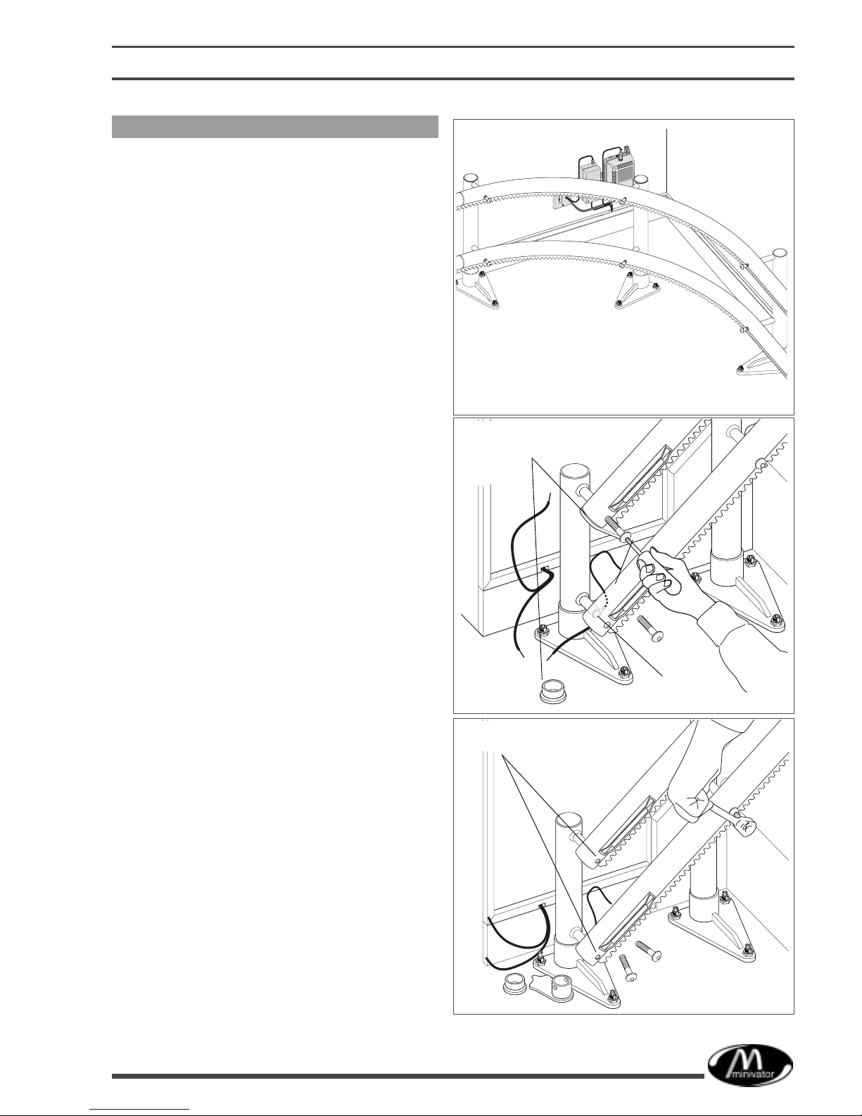
Fig. 2
To install the power supply and handsets
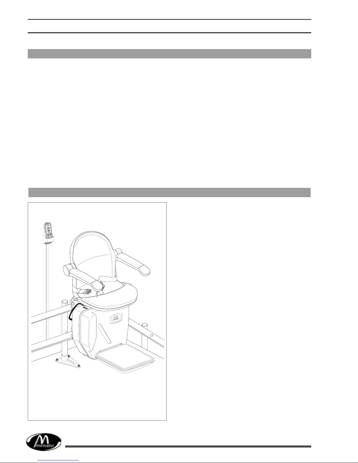
Assess the most appropriate position for the
power supply(ies), and the handset battery back
up box, where it (they) will cause the least
inconvenience for a pedestrian user of the
staircase, and agree the siting with the client.
(This is typically in a corner of the staircase,
where it (they) will be protected by the track
curvature).
Note: Ensure that all components are checked
off against the supplied assembly drawings
before commencing the installation.
Handsets are pre-pro rammed at Minivator as
stand alone units. If only 2 are to be used they
do not require hard wirin , simply fit the 3
batteries into each unit. (Show the client how to
chan e the batteries).
Note: Where multiple handsets are to be
installed (more than ) a separate handset
power supply has to be installed.
Typical schematic drawin s are shown in
Appendix 5 and 6.
Note: It is recommended that a fused mains
spur should be used as a power supply.
If one is not available a connection will have to
be made via an appropriate wall socket, usin
a fused plu .
1Where multiple handsets are used fit all
cables in the most unobtrusive position,
usin 4 core cable, and daisy-chain the
wirin . (Refer to Appendix 5 and 6).
Note: Minivator recommend the use of
16mm self adhesive cable trunkin for a
neater and more secure fittin .
2Where trunkin is bein used, notch or drill
cable entrances/exits as close as possible
to handsets, power supplies, etc, for the
neatest installation (Fi . 2,3).
3Mark the positions required for the stairlift
power supply, and if required the handset
power supply. Use the mountin plate and/
or bracket to act as a template (Fi . 4).
Note: If the handset power supply has
mounting lugs, use the lugs as your template.
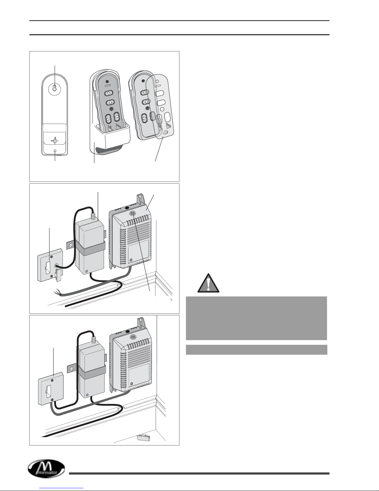
Notch out
trunking
for cable
installation
to power
supplies
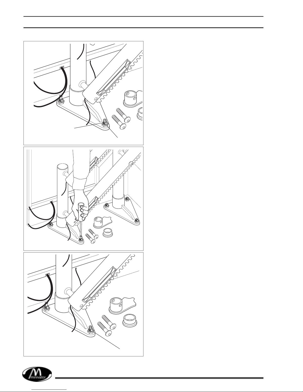
Fig. 3
Notch out trunking for
cable installation
to charge points and
handsets.
ONLY CLIP COVER IN
PLACE WHEN CABLING I
ATI FACTORY
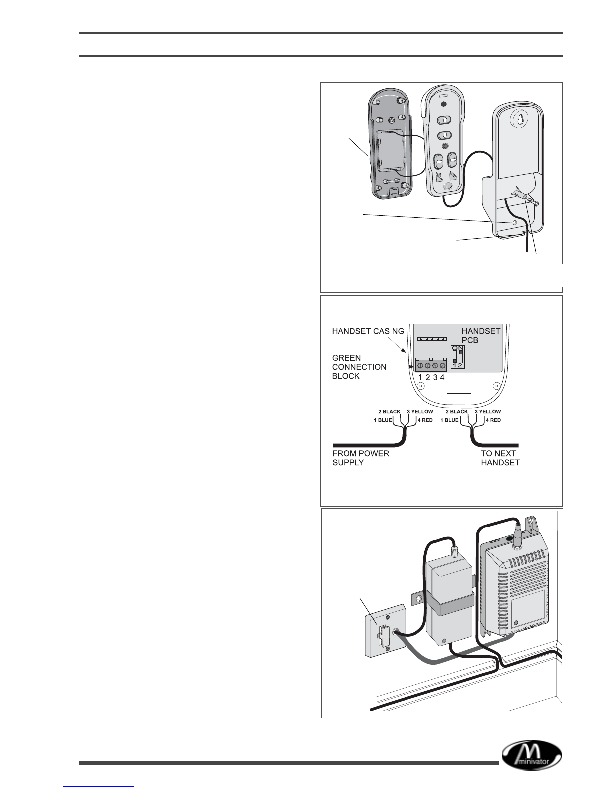
Fig. 4
tairlift power
supply bracket
Handset power supply
(With lugs)
Fused
spur
4 core handset
cable