MINN KOTA MKR-28 User manual

1 | minnkotamotors.com ©2022 Johnson Outdoors Marine Electronics, Inc.
C
• Wire Stripper
• Pencil or marking tool
• Wire Cutter
• Ruler
• Heat Gun
• Drill
• 1-¾" Hole Saw
• 1/8" Drill Bit
• Phillips Screw Driver
Before installing your Trolling Motor Plug and Receptacle, consider
the following:
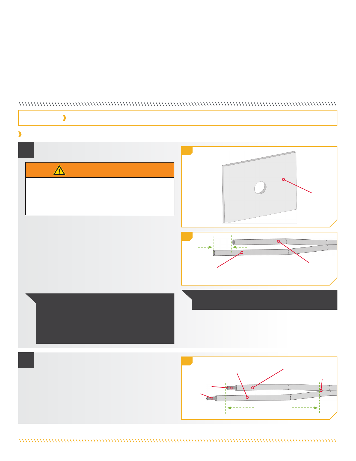
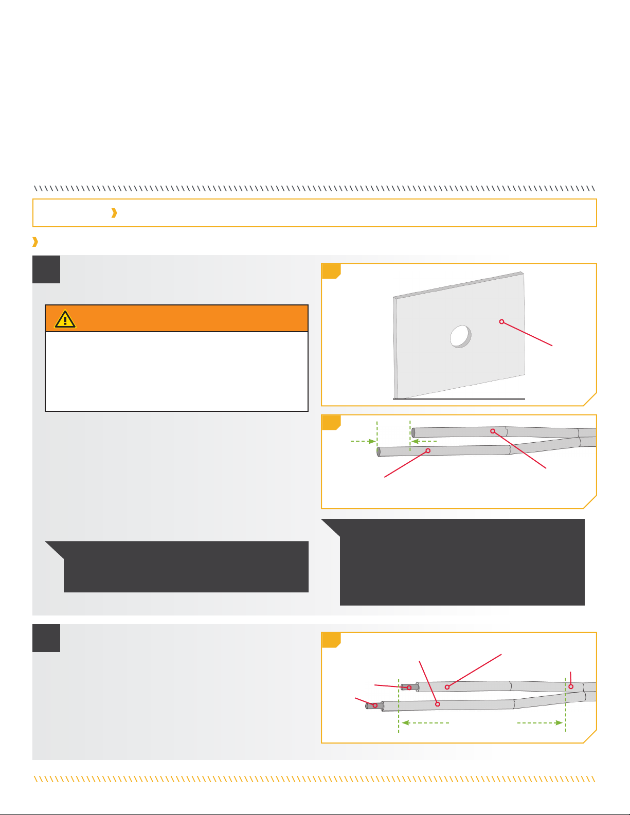
1. The mounting surface needs to have a flat area no less
than 3-¼” wide x 2-½ inches high. Use the Face Plate (Item
#2) to check for clearance at the desired mounting location.
Item /
Assembly Part # Description Qty.
A 2996707 PLUG ASSEMBLY 1
B 2996708 RECEPTACLE 1
C 2990214 COVER-DUST ASSEMBLY 1
2 2376458 PLATE-FACE 1
4 2375425 COVER-SPLICE 1
D
Includes 6-14 2994953 BAG ASM, PLUG SIDE,TM PLUG 1
6 2095400 SHRINK TUBE,16MM, 2”, 4:1 2
8 2375440 SPLICER, 6-10 AWG, TIN PLTD 2
10 2372951 FERRULE, 8 AWG, .47”, TIN PLTD 4
12 2372952 FERRULE,10 AWG, .47”, TIN PLTD 2
14 2376740 KEY-3/32” HEX L, STEEL 1
E
Includes 16-34 2994954 BAG ASM, RECPT SIDE,TM PLUG 1
16 2375402 SHRINK TUBE-24MM ID X 3.5” 2
18 2375442 SPLICER, 2/0-14 AWG 2
20 2372953 FERRULE,1 AWG,.71”,TIN PLT 2
22 2372954 FERRULE,2 AWG,.71”,TIN PLT 2
24 2372955 FERRULE,4 AWG,.71”,TIN PLT 2
26 2372950 FERRULE, 6 AWG, .47”, TIN PLTD 2
28 2372951 FERRULE, 8 AWG, .47”, TIN PLTD 4
30 2372952 FERRULE,10 AWG, .47”, TIN PLTD 2
32 3393400 SCREW-#8-18X1-1/4 PPHSMS SS 4
34 2376741 KEY-3/16” HEX L, STEEL 1
▲2377182 INSTR.SHEET,TROLLNG MTR PLG 1
36 2374651 O-RING (INCLUDED IN ASSEMBLY B) 1
F
Includes A & D 2776707 PLUG ASM, TROLLING MTR PLUG KIT 1
G
Includes B & E 2776708 RECEPTACLE ASM, TRL MTR PLUG 1
TOOLS AND RESOURCES REQUIRED
MOUNTING CONSIDERATIONS
MKR-28
TROLLING MOTOR PLUG AND RECEPTACLE
1865120
✖This part is included in an assembly and cannot be ordered individually.
▲Not shown on Parts Diagram.
WARNING
Do not tin any wires with this installation. Tinned wires could
cause the connection to loosen over time, creating an improper
connection. Improper connections could cause ae electrical
short or extreme fire danger. Follow the installation instructions
provided to avoid product failure and injury.
WARNING
Make sure the power source is disconnected or, if controlled by
a switch, turned OFF before beginning installation of the Plug
Receptacle. Failure to remove power from the Boat Wires could
cause electric shock.
NOTICE: If uncomfortable making this installation, we
recommend having the Motor Plug and Receptacle
installed by a qualified marine installer.
A
F
4
36
B
D
8
12
10
6
14
20
22
24
26
28
30
E
34
18
32
16
G
2
2 | minnkotamotors.com ©2022 Johnson Outdoors Marine Electronics, Inc.
2. Make sure the area under the mounting location is clear to drill holes and that installation hardware will not damage existing
components or wiring below the mounting surface.
3. Make sure that the trolling motor Power Leads and the Boat Wires are not connected to a power source before beginning installation.
4. Test that the Boat Wires can reach the intended mounting location to be attached to the Plug Receptacle. Also, check that the
Trolling Motor Lead Wires can reach the Plug Assembly wires and that there is enough slack that the plug can be both plugged in and
unplugged at the intended location. All wires should not only reach but also have extra slack to allow for ease of installation or repairs
and relieve tension on the final installation. If the wires are not adequate in length, select another location.
5. Determine if the mounting location will work when the Plug Assembly is plugged into the Plug Receptacle. Check for clearance
that will be required for the cords exiting and entering on both sides of the installation. Allow for space for the cords to exist and
accommodate plugging and unplugging the plug as needed.
Trolling Motor Plug and Receptacle Installation
a. Review the Mounting Considerations and determine
an acceptable Mounting Location.
1
2
1b
1c
2d
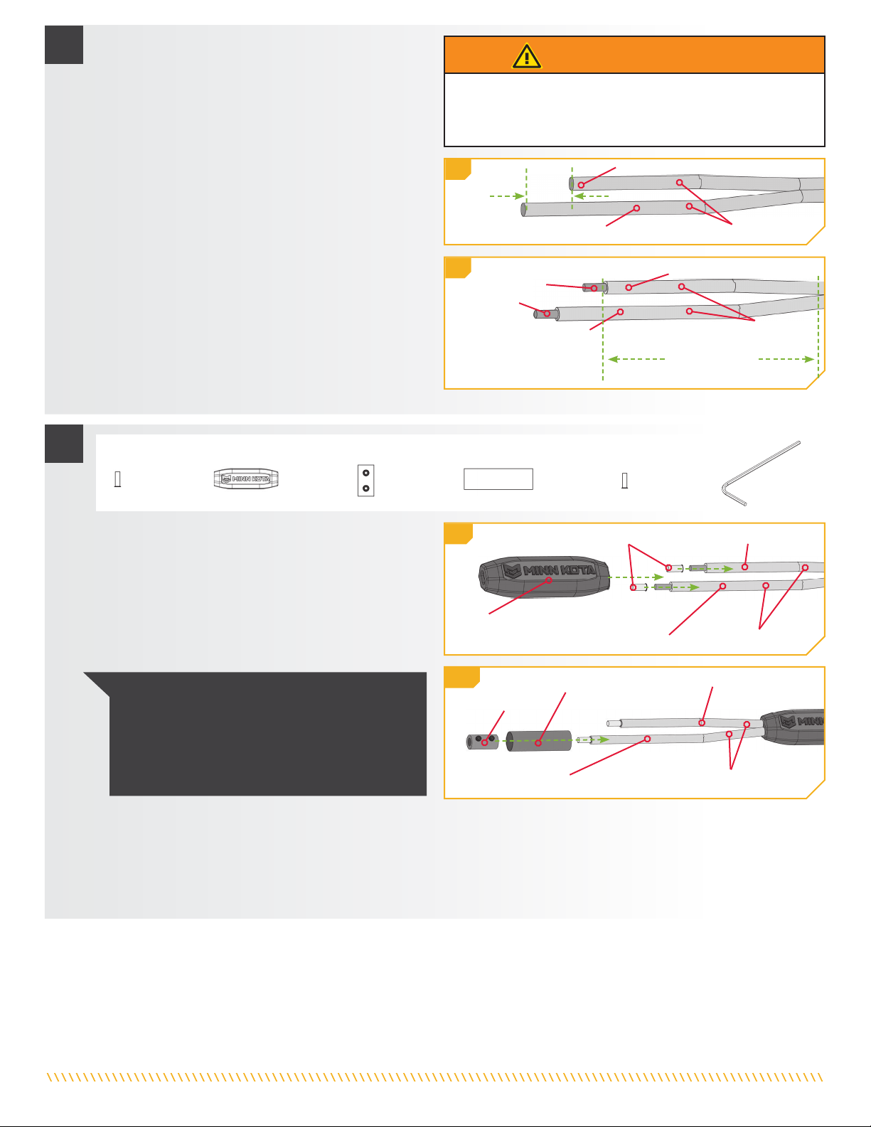
NOTICE: The ends of the Boat Wires may have any sort of
electrical connector that should be removed.
NOTICE: For ease of installation, it is recommended
to stagger the ends of the wires by 1-¼". Make the
Negative (-) Boat Wire the shorter wire of the two.
Staggering the length of the wires will help with the
installation of the hardware used to connect the wires
later in the installation.
INSTALLATION
MountingMounting
LocationLocation
ProtectiveProtective
CoveringCovering
RemovedRemoved
WARNING
Make sure the power source is disconnected or, if controlled
by a switch, turned OFF before beginning installation of the
Plug Receptacle. Failure to remove power from the Boat Wires
could cause electric shock.
b. Once an acceptable Mounting Location is selected,
remove any power leading to the Boat Wires. Use a
Drill with a 1-¾" Hole Saw to drill a hole through the
selected location.
c. With the hole drilled, locate the Boat Wires that the
plug will be connected to. The wires may need to be
trimmed and stripped. Use a Wire Cutter to cut the
wires to remove any terminals or covers that may be
in place.
d. With a Wire Stripper, remove the protective covering
on the wires. It is recommended to remove ½" to
¾" of the protective covering to expose the wires.
Use a Ruler to measure this distance if necessary.
If the Positive (+) and Negative (-) Boat Wires are
fused together, split them so they are separated for a
minimum of 2-½" from the end of the shortest wire.
Positive (+)Positive (+)
Boat WireBoat Wire
Positive (+)Positive (+)
Boat WireBoat Wire
Negative (-)Negative (-)
Boat WireBoat Wire
1-¼"1-¼"
2-½" Minimum2-½" Minimum
SplitSplit
Negative (-)Negative (-)
Boat WireBoat Wire FusedFused
3 | minnkotamotors.com ©2022 Johnson Outdoors Marine Electronics, Inc.
3
4
3e
4i
3f
3g 3h
4j
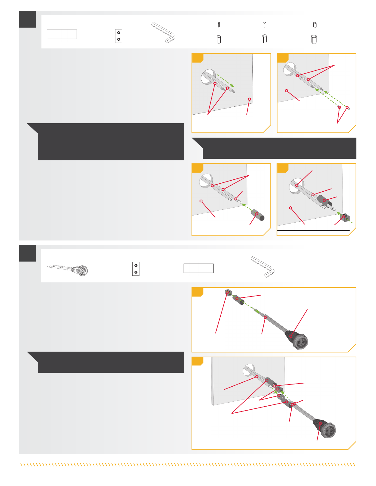
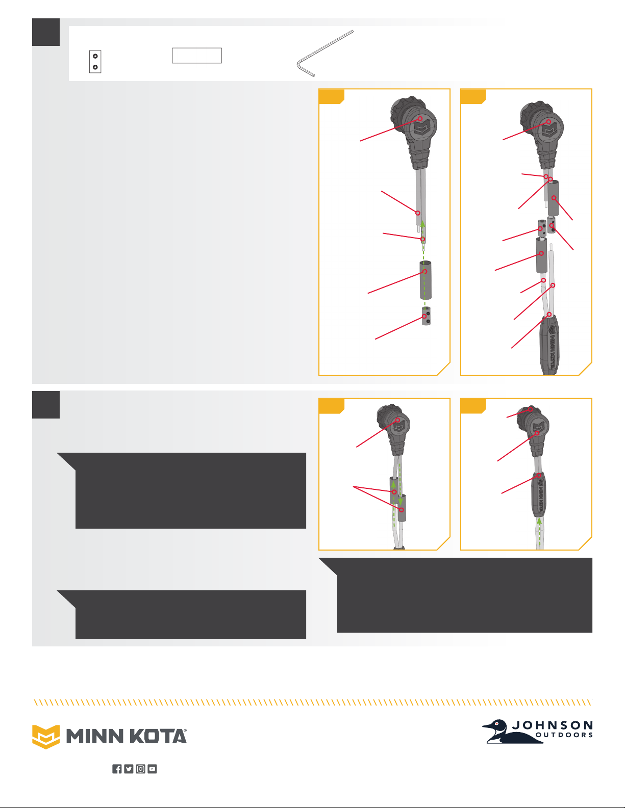
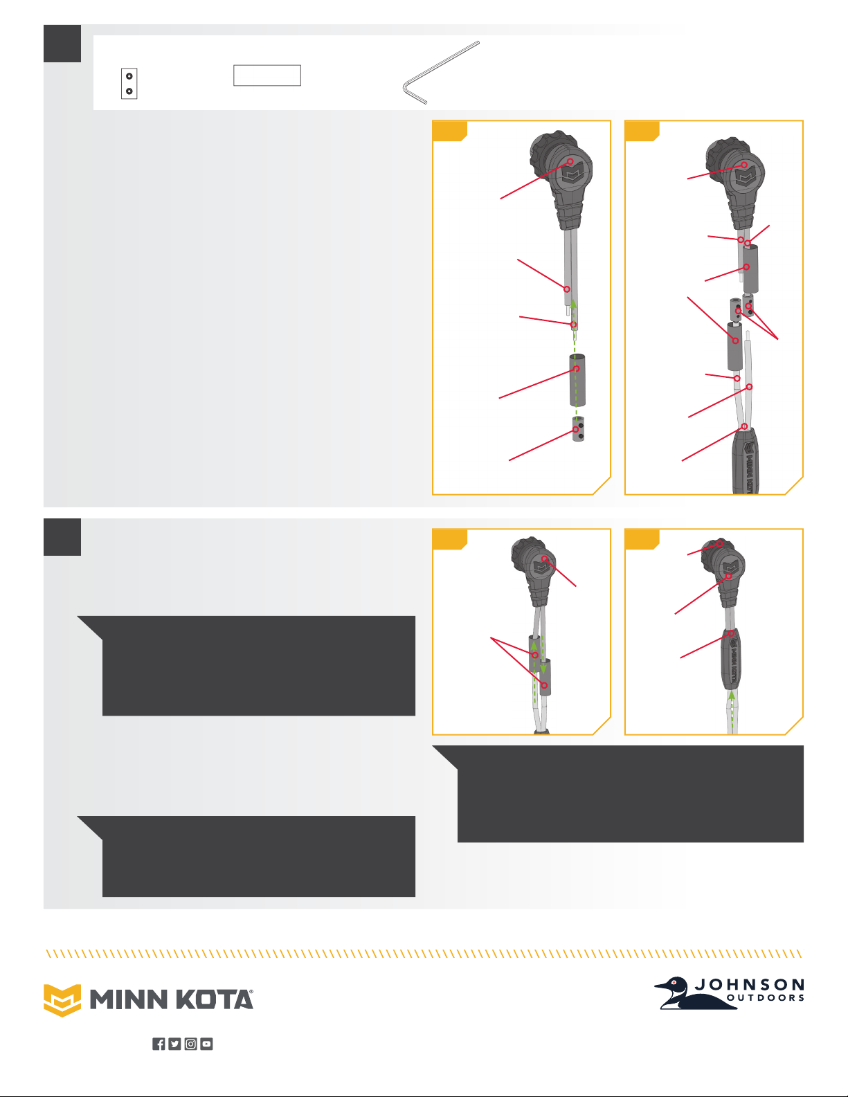
e. Take the Boat Wires and fish them through the 1-¾"
hole that was cut in the Mounting Location. The wires
should pass from the back so that the newly trimmed
ends exit the front of the hole.
f. The Boat Wires that were stripped will be covered with
a Ferrule (Items #20, 22, 24, 26, 28 or 30) to contain
the wire strands. Take two Ferrules and place one at the
end of each wire, encasing all of the wire strands.
h. Take one Splicer (Item #18) and place it on the end
of the Positive (+) Boat Wire. The Splicer is secured to
the Boat Wire over the Ferrule. Secure the Splicer by
tightening the Set Screw with the 3/16" Allen Wrench
(Item # 34) to 20 in-lbs.
ITEM(S) NEEDED
ITEM(S) NEEDED
#16 x 1
#16 x 1
#B x 1
#30 x 2
#24 x 2
#28 x 2
#22 x 2
#26 x 2
#20 x 2
#18 x 1
NOTICE: The positive (+) and negative (-) wires on the
Plug Receptacle should have Ferrules already applied.
BoatBoat
WiresWires
BoatBoat
WiresWires
BoatBoat
WiresWires
BoatBoat
WiresWires Mounting LocationMounting Location
MountingMounting
LocationLocation
MountingMounting
LocationLocation MountingMounting
LocationLocation
Shrink TubeShrink Tube
ShrinkShrink
TubeTube
Shrink TubeShrink Tube
ShrinkShrink
TubesTubes
SplicerSplicer
SplicersSplicers
FerrulesFerrules
Positive (+)Positive (+)
Boat WireBoat Wire
Positive (+)Positive (+)
Wire (red)Wire (red)
Negative (-)Negative (-)
Boat WireBoat Wire
Negative (-)Negative (-)
Wire (black)Wire (black)
Negative (-)Negative (-)
Wire (black)Wire (black)
Plug ReceptaclePlug Receptacle
Plug ReceptaclePlug Receptacle
NOTICE: The Ferrule selected will depend on the boat
wire size. The two extra 8 AWG Ferrules (Item #28) may
only be needed if the Plug Receptacle wires need to be
trimmed or recapped.
NOTICE: Boat Wire sizes vary, so it may be necessary to
use a different sized Ferrule.
Positive (+)Positive (+)
Boat WireBoat Wire
Positive (+)Positive (+)
Boat WireBoat Wire
SplicerSplicer
#18 x 1 #34 x 1
i. The other Splicer and Shrink Tube should be added to
the Plug Receptacle so it can be attached to the Boat
Wires. Take the Plug Receptacle (Item #B) and place
one Shrink Tube (Item #16), followed by one Splicer
(Item #18) on the end of the black Negative (-) Wire of
the Plug Receptacle. Secure the Splicer by tightening
the Set Screw with the 3/16" Allen Wrench (Item #34)
to 20 in-lbs.
j. Take the Plug Receptacle and identify the red Positive
(+) Wire on the Plug Receptacle and align it with the
Positive (+) Boat Wire. Insert it into the Splicer at
the end of the Positive (+) Boat Wire. Take the black
Negative (-) Wire from the Plug Receptacle and align it
with the Negative (-) Boat Wire. Insert it in the Splicer
at the end of the black Negative (-) Wire of the Plug
Receptacle. Secure the Set Screw of both Splicers
with the 3/16” Allen Wrench to 20 in-lbs.
g. With the wires out the front of the Mounting Location, take
one of the two-inch Shrink Tubes (Item #16) and place
one on the end of the longer Positive (+) Boat Wire.
#34 x 1
4 | minnkotamotors.com ©2022 Johnson Outdoors Marine Electronics, Inc.
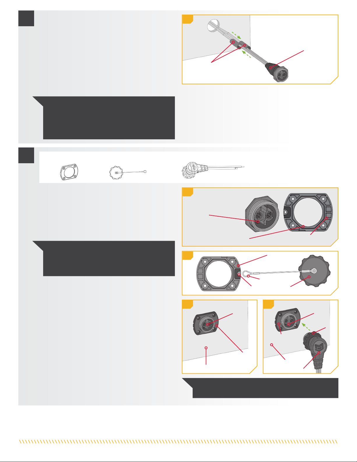
m. The Face Plate (Item #2) is keyed with the Plug
Receptacle. Turn the Face Plate over and notice the
notches along the Inner Circle. These notches are
keyed with the outer edge of the Plug Receptacle
when it sits flush on the mounting surface. This allows
the Face Plate or Plug Receptacle to be rotated in 45
degree increments.
6
6m
6n
ITEM(S) NEEDED
#2 x 1 #C x 1 #A x 1
6o 6p
Inner CircleInner Circle
Plug ReceptaclePlug Receptacle
Face PlateFace Plate
(back)(back)
Face PlateFace Plate
(back)(back)
PlugPlug
ReceptacleReceptacle PlugPlug
ReceptacleReceptacle
ThreadedThreaded
CollarCollar
Face PlateFace Plate
(front)(front)
Face PlateFace Plate
(front)(front)
Mounting SurfaceMounting Surface
MountingMounting
SurfaceSurface
Plug AssemblyPlug Assembly
LoopLoop
Dust CoverDust Cover
HookHook
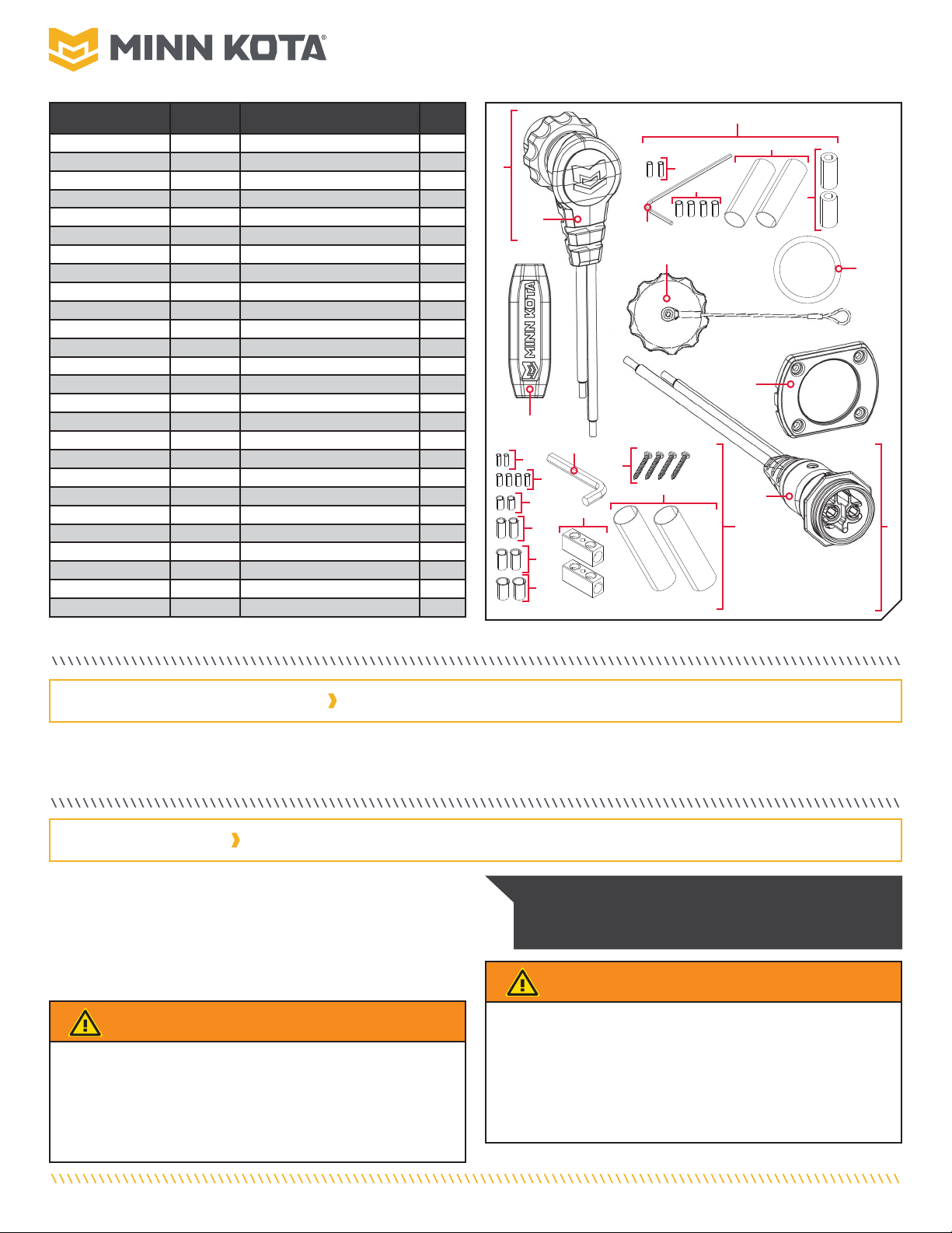
5k. Once the Splicers are secure on both wires, take the
Shrink Tubes and slide them over the Splicers. The
Shrink Tube should be centered over the Splicer and
completely cover the wire connections.
l. When satisfied with the position, secure the Shrink
Tubes in place with a Heat Gun. Ensure that there is
no opening around the Shrink Tubes when heated.
Push the wires and the Plug Receptacle into the
drilled hole until the Plug Receptacle sits against
the mounting surface.
5k
ShrinkShrink
TubesTubes
Plug ReceptaclePlug Receptacle
NOTICE: The Shrink Tubes are meant to water
proof the connection between the Plug Receptacle
and the Boat Wires. Make sure there are no gaps
around the wires that would allow water to reach
the connection.
NOTICE: Tethering the Dust Cap to the Face Plate
during installation is optional. The Dust Cap can be
stowed away when the plug is in use and should be
replaced for storage or transport.
n. On the back side of the Face Plate, there is also
a hook to attach the Dust Cover (Item #C). Determine
if the Dust Cover will hang to the right or the left and
turn the hook on the Face Plate to the appropriate
direction.
o. Flip the Face Plate so the keys on the Inner Circle
are towards the mounting surface and place it over
the Plug Receptacle. It should be seated on the
mounting surface.
p. Take the Plug Assembly (Item #A) and plug it into
the Plug Receptacle. The Plug Assembly and Plug
Receptacle are also keyed with each other. Orientate
the Plug Assembly and Plug Receptacle so they can
be fully pushed together. The Threaded Collar on the
Plug Assembly does not have to be tightened.
NOTICE: Use the Dust Cap when the plug is not in use to
insure optimal water-tight protection to electrical contacts.
5 | minnkotamotors.com ©2022 Johnson Outdoors Marine Electronics, Inc.
8
8u
8v
ITEM(S) NEEDED
#32 x 4
FaceFace
PlatePlate
HookHook
LoopLoop
Dust CoverDust Cover
FaceFace
PlatePlate
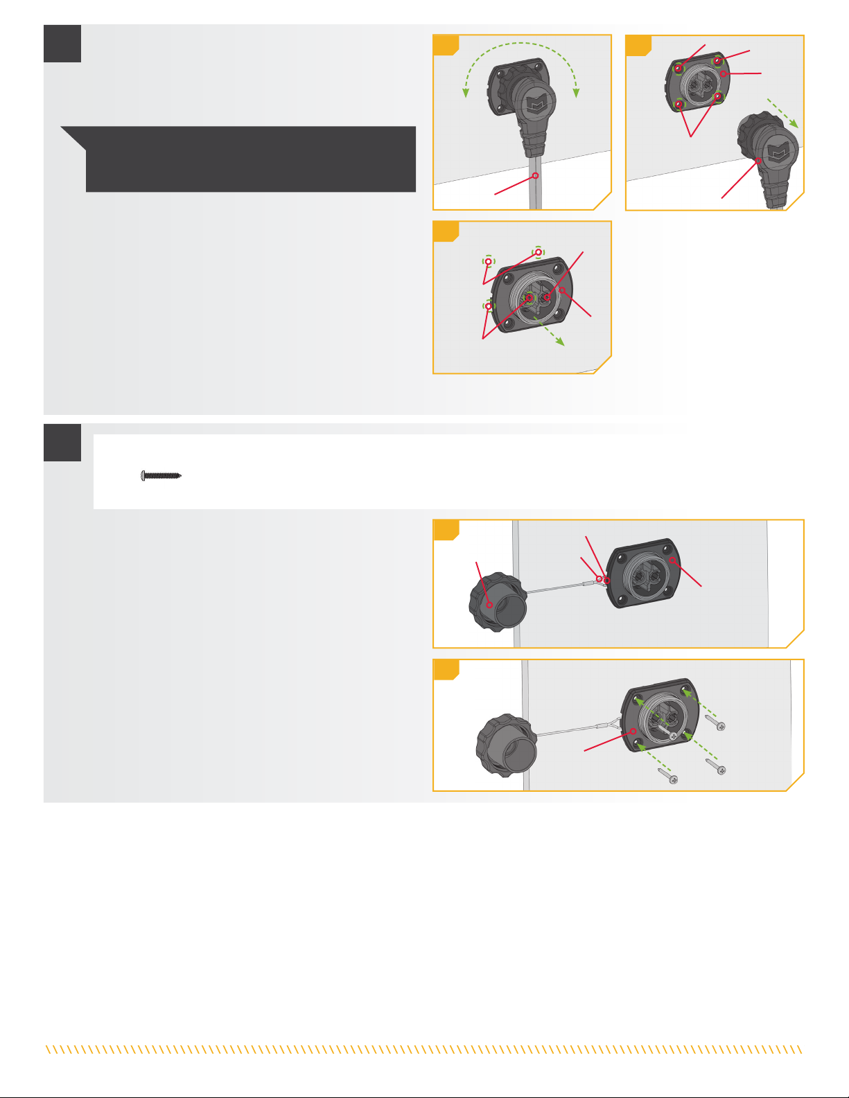
t. With pilot holes drilled, push the wires, Face
Plate and Plug Receptacle back in place on the
Mounting Surface.
u. Double check the location of the Hook on the back
side of the Face Plate. The Loop in the cable of the
Dust Cover should be placed in the Hook of the Face
Plate. Once secure, push the Face Plate all the way
back against the mounting surface. Ensure the Plug
Receptacle is positioned as previously noted.
v. Realign the drilled pilot holes with the screw holes on
the Face Plate. Secure the Face Plate with four #8-18
x 1-¼ Screws (Item #32) using a Phillips Screw Driver.
7r
q. Turn the entire assembly to the right or left until the
Cord from the Plug Assembly is in an acceptable
location. Check for clearance of other items on the
mounting surface and if the cord will interfere with the
operation of anything in the area.
r. Once in an acceptable location, take a pen or marking
tool and mark the mounting surface in each of the
screw holes on the Face Plate. Make note of the
orientation of the Plug for correct placement in the
next steps of installation. With the locations marked,
remove the Plug Assembly from the Plug Receptacle
and set it aside.
s. Lift the Plug Receptacle, Face Plate and wires forward
out of the drilled hole and leave it hang out of the way.
Take a Drill with an 1/8" Drill Bit and drill pilot holes
into the Mounting Surface on the Marked Locations.
77q
7s
Plug AssemblyPlug Assembly
CordCord
Marked LocationMarked Location
Marked LocationMarked Location
FaceFace
PlatePlate
PlugPlug
ReceptacleReceptacle
FaceFace
PlatePlate
Marked LocationMarked Location
MarkedMarked
LocationLocation
NOTICE: Make sure the location also allows for the
Plug to be connected and disconnected. Then the
Locking Collar can be secured once the Plug is in use.
6 | minnkotamotors.com ©2022 Johnson Outdoors Marine Electronics, Inc.
9
ITEM(S) NEEDED
#4 x 1 #6 x 1
w. Locate the Power Leads for the trolling motor. Turn the
power to the motor “off” and remove the motor Power
Leads from any power source.
x. The wires may need to be trimmed and stripped.
Make sure that the wires are long enough to reach
the installation location. Use a Wire Cutter to cut the
wires to remove any terminals or covers that may be
in place. Cut the wires so that the ends of the wires
are staggered, and the Negative (-) Power Lead is
approximately 1-¼" longer than the Positive (+)
Power Lead.
y. With a Wire Stripper remove the protective covering
on the wires. It is recommended to remove ½" to ¾"
of the protective covering to expose the wires. Use
a Ruler to measure this distance if necessary. If the
Positive (+) Power Lead and Negative (-) Power Lead
of the Trolling Motor Wires are fused together, split
them so they are separated by a minimum of 2-½”
from the end of the shortest wire.
WARNING
Make sure that the trolling motor wires are not connected
to a power source. Failure to remove power could cause
electric shock.
9x
9y
Trolling Motor WiresTrolling Motor Wires
Positive (+) Power LeadPositive (+) Power Lead
Positive (+) Power LeadPositive (+) Power Lead
Positive (+) Power LeadPositive (+) Power Lead
Positive (+) Power LeadPositive (+) Power Lead
Negative (-) Power LeadNegative (-) Power Lead
Negative (-) Power LeadNegative (-) Power Lead
Negative (-) Power LeadNegative (-) Power Lead
Negative (-) Power LeadNegative (-) Power Lead
Trolling Motor WiresTrolling Motor Wires
Trolling Motor WiresTrolling Motor Wires
Trolling Motor WiresTrolling Motor Wires
ProtectiveProtective
CoveringCovering
RemovedRemoved
1-¼"1-¼"
2-½" Minimum2-½" Minimum
SplitSplit
10
z. Both the Positive (+) Power Lead and Negative (-)
Power Lead of the Trolling Motor Wires should be
covered with a Ferrule. Take two 10 AWG or 8 AWG
Ferrules (Item #10) or (Item #12) and place one on
the end of each of the motor wires. With the Ferrules
placed, take the Splice Cover (Item #4) and thread
both the Positive (+) and Negative (-) Power Lead of
the Trolling Motor Wires through it.
#10 x 2 #12 x 2 #14 x 1#8 x 1
Splice CoverSplice Cover
FerrulesFerrules
NOTICE: The 10 AWG Ferrules are the smallest
in the provided hardware. The two extra 8 AWG
Ferrules (Item #10) may only be needed if the Plug
Assembly wires need to be trimmed or recapped.
Wire sizes vary, so it may be necessary to use a
different sized Ferrule.
10z
10aa
SplicerSplicer
Shrink TubeShrink Tube
aa. Take one of the two-inch Shrink Tubes (Items #6) and
place one on the end of the longer Negative (-) Power
Lead of the Trolling Motor Wire. Take one Splicer (Item
#8) and place it on the end of the same wire. Secure
the Splicer by tightening the Set Screw with a 3/32"
Allen Wrench (Item #14) to 20 in-lbs.
11
12
ITEM(S) NEEDED
#8 x 1
ad. Once the Splicers are secure on both wires, take the
Shrink Tubes and slide them over the Splicers. The
Shrink Tubes should be centered over the Splicers and
completely cover the wire connections.
Minn Kota Consumer & Technical Service
Johnson Outdoors Marine Electronics, Inc.
PO Box 8129
Mankato, MN 56001
121 Power Drive
Mankato, MN 56001
Phone (800) 227-6433
Fax (800) 527-4464
minnkotamotors.com
©2022 Johnson Outdoors Marine Electronics, Inc.
All rights reserved.
Part #2377182 Rev A 05/22ECN 42520
For warranty information, please visit minnkotamotors.com.
11ad 11ae
Plug AssemblyPlug Assembly
Plug AssemblyPlug Assembly
Splice CoverSplice Cover
Shrink TubeShrink Tube
Positive PowerPositive Power
Lead (+)Lead (+)
Negative PowerNegative Power
Lead (-)Lead (-)
Negative (-)Negative (-)
Power LeadPower Lead
SplicerSplicer
SplicerSplicer
SplicerSplicer
Shrink TubeShrink Tube
ShrinkShrink
TubeTube
ShrinkShrink
TubeTube
11ac
#6 x 1
ab. The other Splicer and Shrink Tube should be added to
the Plug Receptacle so it can be attached to the Boat
Wires. Take the Plug Receptacle (Item #B) and place
one Shrink Tube (Item #6), followed by one Splicer
(Item #8) on the end of the black Negative (-) Wire of
the Plug Receptacle. Secure the Splicer by tightening
the Set Screw with a 3/32" Allen Wrench (Item #14) to
20 in-lbs.
ac. Take the Plug Assembly and identify the red Positive
(+) Power Lead on the Plug Assembly and align
it with the Positive (+) Power Lead on the Trolling
Motor Wires. Insert it into the Splicer at the end of
the Positive (+) Lead Wire from the Plug Assembly.
Take the black Negative (-) Power Lead from the Plug
Assembly and align it with the Negative (-) Power Lead
from the Trolling Motor Wires. Insert it in the Splicer at
the end of the black Negative (-) Power Lead of from
the Trolling Motor Wires. Secure the Set Screw of both
Splicers with the 3/32” Allen Wrench.
NOTICE: The Shrink Tubes are meant to water
proof the connection between the Plug Assembly
and the Trolling Motor Wires. Make sure there are
no gaps around the wires that would allow water to
reach the connection.
NOTICE: When disconnecting the Plug Assembly
from the Receptacle, be sure to install and tighten the
Dust Cap. This will prevent water or debris intrusion.
PlugPlug
AssemblyAssembly
PlugPlug
AssemblyAssembly
11ab
Positive (+)Positive (+)
Power LeadPower Lead
Positive (+)Positive (+)
Power LeadPower Lead
Negative (-)Negative (-)
Power LeadPower Lead
TrollingTrolling
Motor WiresMotor Wires
ae. When satisfied with the position, secure the Shrink
Tubes in place with a Heat Gun. Then slide the Splice
Cover over the Shrink Tubes to complete
the installation.
NOTICE: When connecting the Plug Assembly to the
Receptacle, be sure to tighten the Threaded Collar
to ensure a proper water-tight seal. A water-tight seal
protects electrical contacts. Failure to tighten the
Threaded Collar could result in water intrusion.
ThreadedThreaded
CollarCollar
#14 x 1
8 | minnkotamotors.com ©2022 Johnson Outdoors Marine Electronics, Inc.
C
• Pince à dénuder
• Crayon ou outil
de marquage
• Coupe-fil
• Règle
• Pistolet thermique
• Perceuse
• Scie-cloche de 1 ¾ po
(44,45 mm)
• Mèche de 1/8 po (3,17 mm)
• Tournevis cruciforme
Avant d’installer la fiche et la prise de votre moteur de pêche à la
traîne, veuillez tenir compte des éléments suivants :
1. La surface de montage doit être plane, et les dimensions ne
doivent pas être inférieures à 3 ¼ po (82,55 mm) de largeur sur
2 ½ po (63,5 mm) de hauteur. Utilisez le couvercle (article nº 2)
pour vérifier le dégagement à l’emplacement de montage souhaité.
Article/
Assemblage Nº de
pièce Description Qté
A 2996707 PLUG ASSEMBLY 1
B 2996708 RECEPTACLE 1
C 2990214 COVER-DUST ASSEMBLY 1
2 2376458 PLATE-FACE 1
4 2375425 COVER-SPLICE 1
D - Comprend 6 à 14 2994953 BAG ASM, PLUG SIDE,TM PLUG 1
6 2095400 SHRINK TUBE,16MM, 2”, 4:1 2
8 2375440 SPLICER, 6-10 AWG, TIN PLTD 2
10 2372951 FERRULE, 8 AWG, .47”, TIN PLTD 4
12 2372952 FERRULE,10 AWG, .47”, TIN PLTD 2
14 2376740 KEY-3/32” HEX L, STEEL 1
E - Comprend 16 à 34 2994954 BAG ASM, RECPT SIDE,TM PLUG 1
16 2375402 SHRINK TUBE-24MM ID X 3.5” 2
18 2375442 SPLICER, 2/0-14 AWG 2
20 2372953 FERRULE,1 AWG,.71”,TIN PLT 2
22 2372954 FERRULE,2 AWG,.71”,TIN PLT 2
24 2372955 FERRULE,4 AWG,.71”,TIN PLT 2
26 2372950 FERRULE, 6 AWG, .47”, TIN PLTD 2
28 2372951 FERRULE, 8 AWG, .47”, TIN PLTD 4
30 2372952 FERRULE,10 AWG, .47”, TIN PLTD 2
32 3393400 SCREW-#8-18X1-1/4 PPHSMS SS 4
34 2376741 KEY-3/16” HEX L, STEEL 1
▲2377182 INSTR.SHEET,TROLLNG MTR PLG 1
36 2374651 O-RING (INCLUDED IN ASSEMBLY B) 1
F - Comprend A et D 2776707 PLUG ASM, TROLLING MTR PLUG KIT 1
G - Comprend B et E 2776708 RECEPTACLE ASM, TRL MTR PLUG 1
OUTILS ET RESSOURCES NÉCESSAIRES
FACTEURS DE MONTAGE
MKR-28
FICHE ET PRISE DU MOTEUR DE PÊCHE À LA TRAÎNE
1865120
✖Cette pièce est incluse dans un ensemble et ne peut pas être commandée individuellement. ▲Non illustrée sur le schéma des pièces.
AVERTISSEMENT
N’étamez pas les fils dans le cadre de cette installation. Des
fils étamés pourraient causer le desserrage de la connexion au
fil du temps et créer une mauvaise connexion. Des mauvaises
connexions pourraient causer un court-circuit électrique ou un
risque extrême d’incendie. Suivez les instructions d’installation
fournies pour éviter une défaillance du produit et des blessures.
AVERTISSEMENT
Assurez-vous que la source d’alimentation est débranchée ou,
si elle est commandée par un interrupteur, qu’elle est éteinte
avant de procéder à l’installation de la prise de fiche. Ne pas
supprimer l’alimentation des fils du bateau pourrait causer une
décharge électrique.
AVIS : Si vous n’êtes pas à l’aise de procéder à
l’installation, nous vous recommandons de faire installer la
fiche et la prise du moteur par un installateur compétent.
A
F
4
36
B
D
8
12
10
6
14
20
22
24
26
28
30
E
34
18
32
16
G
2
9 | minnkotamotors.com ©2022 Johnson Outdoors Marine Electronics, Inc.
2. Assurez-vous que la zone sous l’emplacement de montage est libre pour y percer des trous et que la quincaillerie d’installation
n’endommagera pas les composants en place ou le câblage situé sous la surface de montage.
3. Assurez-vous que les câbles d’alimentation du moteur de pêche à la traîne et les fils du bateau ne sont pas connectés à une source
d’alimentation avant de procéder à l’installation.
4. Vérifiez que les fils du bateau peuvent atteindre l’emplacement de montage prévu pour être fixés à la prise de fiche. Vérifiez
aussi que les fils conducteurs du moteur de pêche à la traîne peuvent atteindre les fils de l’ensemble de fiche, et qu’il y a assez de
jeu pour que la fiche puisse être branchée et débranchée à l’emplacement prévu. Tous les fils devraient non seulement atteindre
l’emplacement souhaité, mais aussi avoir suffisamment de jeu pour faciliter l’installation ou les réparations, et libérer la tension sur
l’installation finale. Si les fils ne sont pas suffisamment longs, choisissez un autre emplacement.
5. Déterminez si l’emplacement de montage convient lorsque l’ensemble de fiche est branché dans la prise de fiche. Vérifiez le
dégagement requis pour les cordons déjà en place et ceux qui entrent sur les deux côtés de l’installation. Donnez de l’espace aux
cordons en place et facilitez le branchement et le débranchement de la fiche au besoin.
Installation de la fiche et de la prise du moteur de pêche à la traîne
a. Passez en revue les facteurs de montage à tenir en
compte pour déterminer un emplacement de
montage acceptable.
1
2
1b
1c
2d
AVIS : Les extrémités des fils du bateau peuvent
présenter tout type de connecteur électrique qui doit
être retiré.
AVIS : Pour faciliter l’installation, nous vous
recommandons de décaler les extrémités des fils de 1 ¼
po (31,75 mm). Faites en sorte que le fil de bateau négatif
(-) soit le plus court des deux fils. Décaler la longueur des
fils facilitera l’installation de la quincaillerie utilisée pour
raccorder les fils ultérieurement dans l’installation.
INSTALLATION
EmplacementEmplacement
de montagede montage
RevêtementRevêtement
ProtecteurProtecteur
RetiréRetiré
AVERTISSEMENT
Assurez-vous que la source d’alimentation est débranchée ou,
si elle est commandée par un interrupteur, qu’elle est éteinte
avant de procéder à l’installation de la prise de fiche. Ne pas
supprimer l’alimentation des fils du bateau pourrait causer
une décharge électrique.
b. Lorsqu’un emplacement de montage acceptable est
choisi, retirez toute alimentation acheminée aux fils
du bateau. Utilisez une perceuse et une scie-cloche
de 1 ¾ po (44,45 mm) pour percer un trou dans
l’emplacement choisi.
c. Le trou étant percé, repérez les fils du bateau auxquels
la fiche sera raccordée. Les fils peuvent devoir être
taillés et dénudés. Utilisez un coupe-fil pour couper les
fils et retirez les bornes ou couvercles en place.
d. Au moyen d’une pince à dénuder, retirez le
revêtement protecteur des fils. Nous vous
recommandons de retirer environ ½ po (12,7 mm)
à ¾ po (19,05 mm) de longueur du revêtement
protecteur pour exposer les fils. Utilisez une règle
pour mesurer cette longueur si nécessaire. Si les fils
de bateaux positif (+) et négatif (-) sont fusionnés
ensemble, divisez-les de manière à les séparer d’au
moins 2 ½ po (63,5 mm) à partir de l’extrémité du fil
le plus court.
Fil de bateauFil de bateau
positif (+)positif (+)
Fil de bateauFil de bateau
positif (+)positif (+)
Fil de bateauFil de bateau
négatif (-)négatif (-)
1 ¼ po1 ¼ po
(31,75(31,75
mm)mm)
SéparationSéparation
minimale de 2 1/2 po (63,5 mm)minimale de 2 1/2 po (63,5 mm)
Fil de bateauFil de bateau
négatif (-)négatif (-)
FusionnésFusionnés

10 | minnkotamotors.com ©2022 Johnson Outdoors Marine Electronics, Inc.
3
4
3e
4i
3f
3g 3h
4j
e. Prenez les fils du bateau et acheminez-les par le
trou de 1 ¾ po (44,45 mm) qui était coupé dans
l’emplacement de montage. Les fils devraient passer
par l’arrière de manière à ce que les extrémités
nouvellement taillées sortent par l’avant du trou.
f. Les fils du bateau qui étaient dénudés seront recouverts
d’une virole (articles nº 20, 22, 24, 26, 28 ou 30) pour
contenir les brins du fil. Prenez les deux viroles et mettez-
en une à l’extrémité de chaque fil, recouvrant ainsi tous
les brins du fil.
h. Prenez un épisseur (article nº 18) et mettez-le à l’extrémité
du fil de bateau positif (+). L’épisseur est fixé au fil du
bateau, sur la virole. Fixez bien l’épisseur en serrant la vis
de pression au moyen d’une clé hexagonale de 3/16 po
(4,72 mm) (article nº 34) à 20 po-lb (2,25 Nm).
ARTICLE(S) REQUIS
ARTICLE(S) REQUIS
#16 x 1
#16 x 1
#B x 1
#30 x 2
#24 x 2
#28 x 2
#22 x 2
#26 x 2
#20 x 2
#18 x 1
AVIS : Les fils positif (+) et négatif (-) de la prise de fiche
devraient déjà comporter des viroles.
Fils duFils du
bateaubateau
Fils duFils du
bateaubateau
Fils du bateauFils du bateau
Fils duFils du
bateaubateau
Emplacement deEmplacement de
montagemontage
Emplacement deEmplacement de
montagemontage
EmplacementEmplacement
de montagede montage
EmplacementEmplacement
de montagede montage
GaineGaine
thermorétrécissablethermorétrécissable
GaineGaine
thermorétrécissablethermorétrécissable
Gaine thermorétrécissableGaine thermorétrécissable
GainesGaines
thermorétrécissablesthermorétrécissables
ÉpisseurÉpisseur
ÉpisseursÉpisseurs
VirolesViroles
Fil de bateauFil de bateau
positif (+)positif (+)
Fil positif (+)Fil positif (+)
(rouge)(rouge)
Fil de bateauFil de bateau
négatif (-)négatif (-)
Fil négatif (-) (noir)Fil négatif (-) (noir)
Fil négatif (-) (noir)Fil négatif (-) (noir)
Prise de fichePrise de fiche
Prise de fichePrise de fiche
AVIS : La virole sélectionnée dépendra de la taille du fil du
bateau. Les deux viroles de calibre 8 AWG (articles nº 28)
peuvent seulement être requises si les fils de la prise de fiche
ou de l’ensemble de fiche doivent être taillés ou rebouchés.
AVIS : La taille des fils du bateau varie, il peut donc être
nécessaire d’utiliser une virole d’une autre taille.
Fil de bateauFil de bateau
positif (+)positif (+)
Fil de bateauFil de bateau
positif (+)positif (+)
ÉpisseurÉpisseur
#18 x 1 #34 x 1
i. L’autre épisseur et la gaine thermorétrécissable
devraient être ajoutés à la prise de fiche, afin de pouvoir
être fixés aux fils du bateau. Prenez la prise de fiche
(article nº B) et mettez un tube thermorétrécissable
(article nº 16), suivi d’un épisseur (article nº 18) à
l’extrémité du fil négatif (-) noir de la prise de fiche.
Fixez bien l’épisseur en serrant la vis de pression au
moyen d’une clé hexagonale de 3/16 po (4,72 mm)
(article nº 34), à 20 po-lb (2,25 Nm).
j. Prenez la prise de fiche et identifiez le fil positif (+)
rouge dessus, puis alignez-le sur le fil de bateau positif
(+). Insérez-le dans l’épisseur à l’extrémité du fil de
bateau positif (+). Prenez le fil négatif (-) noir de la prise
de fiche et alignez-le sur le fil de bateau négatif (-).
Insérez-le dans l’épisseur à l’extrémité de fil négatif (-)
noir de la prise de fiche. Fixez bien la vis de pression
des deux épisseurs au moyen d’une clé hexagonale de
3/16 po (4,72 mm) à 20 po-lb (2,25 Nm).
g. Les fils étant sortis à l’avant de l’emplacement de
montage, prenez une des gaines thermorétrécissables
de 2 po (50,8 mm) (articles nº 16) et mettez-la à
l’extrémité du fil de bateau positif (+) le plus long.
#34 x 1

11 | minnkotamotors.com ©2022 Johnson Outdoors Marine Electronics, Inc.
m. Le couvercle (article nº 2) est fixé sur la prise de fiche.
Retournez le couvercle et remarquez les encoches
pratiquées le long du cercle intérieur. Ces encoches
sont conçues pour s’assoir sur la bordure extérieure
de la prise de fiche lorsque celle-ci repose de manière
à affleurer la surface de montage. Cela permet au
couvercle ou à la prise de fiche d’être tourné par
incrément de 45 degrés.
6
6m
6n
ARTICLE(S) REQUIS
#2 x 1 #C x 1 #A x 1
6o 6p
Cercle intérieurCercle intérieur
Prise de fichePrise de fiche
CouvercleCouvercle
(arrière)(arrière)
CouvercleCouvercle
(arrière)(arrière)
Prise dePrise de
fichefiche Prise dePrise de
fichefiche
CollierCollier
filetéfileté
CouvercleCouvercle
(avant)(avant)
CouvercleCouvercle
(avant)(avant)
Surface de montageSurface de montage
Surface de montageSurface de montage
Ensemble de ficheEnsemble de fiche
BoucleBoucle
Couvercle antipoussièreCouvercle antipoussière
CrochetCrochet
5k. Lorsque les épisseurs sont bien fixés sur les deux fils,
prenez les gaines thermorétrécissables et glissez-les
sur les épisseurs. La gaine thermorétrécissable devrait
être centrée sur l’épisseur et couvrir complètement
les fils de raccordement.
l. Lorsque vous êtes satisfait de la position, fixez bien
les gaines thermorétrécissables en place au moyen
d’un pistolet thermique. Assurez-vous qu’il n’y a pas
d’ouverture autour des gaines thermorétrécissables
lorsqu’elles sont chauffées. Poussez les fils et la prise
de fiche dans le trou percé de manière à ce que la
prise de fiche repose contre la surface de montage.
5k
GainesGaines
thermorétrécissablesthermorétrécissables
Prise de fichePrise de fiche
AVIS : Les gaines thermorétrécissables visent à rendre
étanche la connexion reliant la prise de fiche et les fils du
bateau. Assurez-vous qu’il n’y a pas de vides autour des fils
pouvant permettre à l’eau d’atteindre la connexion.
AVIS : Vous n’êtes pas obligé d’attacher le
capuchon antipoussière au couvercle. Le capuchon
antipoussière peut être rangé lorsque la fiche
est utilisée et doit être remis en place lors de
l’entreposage ou du transport.
n. Sur la face arrière du couvercle, il y a aussi un
crochet pour fixer le couvercle antipoussière (article
nº C). Déterminez si le couvercle antipoussière sera
accroché à droite ou à gauche, puis tournez le crochet
sur le couvercle dans la bonne direction.
o. Relevez le couvercle de manière à ce que les clavettes
du cercle intérieur soient orientées vers la surface de
montage et fixez-le sur la prise de fiche. Le couvercle
devrait reposer sur la surface de montage.
p. Prenez l’ensemble de fiche (article nº A) et branchez-
le dans la prise de fiche. L’ensemble de fiche et
la prise de fiche sont aussi conçus pour être fixés
ensemble. Orientez l’ensemble de fiche et la prise
de fiche de manière à ce qu’ils soient entièrement
engagés. Il n’est pas nécessaire de serrer le collet
fileté sur l’ensemble de fiche.
AVIS : Utilisez le capuchon antipoussière lorsque la fiche
n’est pas utilisée pour une protection étanche maximale
contre les contacts électriques.

12 | minnkotamotors.com ©2022 Johnson Outdoors Marine Electronics, Inc.
8
8u
8v
ARTICLE(S) REQUIS
#32 x 4
CouvercleCouvercle
CrochetCrochet
BoucleBoucle
CouvercleCouvercle
antipoussièreantipoussière
CouvercleCouvercle
t. Les avant-trous étant percés, remettez en place les
fils, le couvercle et les prises de fiche sur la surface
de montage.
u. Revérifiez l’emplacement du crochet sur la face
arrière du couvercle. La boucle dans le câble du
couvercle antipoussière devrait être mise dans le
crochet du couvercle. Une fois bien fixé, repoussez
le couvercle jusqu’à la surface de montage. Assurez-
vous que la prise de fiche est positionnée comme
indiqué précédemment.
v. Réalignez les avant-trous percés sur les trous de vis
du couvercle. Fixez bien le couvercle avec quatre vis
nº 8-18 x 1 ¼ po (31,75 mm) (article nº 32) au moyen
d’un tournevis cruciforme.
7r
q. Tournez l’ensemble complet vers la droite ou la
gauche jusqu’à ce que le cordon de l’ensemble de
fiche soit dans un bon emplacement. Vérifiez le
dégagement des autres articles sur la surface de
montage et vérifiez si le cordon risque de nuire au
fonctionnement de tout élément dans la zone.
r. Lorsque vous êtes dans un emplacement acceptable,
prenez un stylo ou un outil de marquage et marquez
la surface de montage dans chacun des trous de vis
sur le couvercle. Notez l’orientation de la fiche pour
le bon emplacement dans les prochaines étapes
de l’installation. Les emplacements étant marqués,
retirez l’ensemble de fiche de la prise de fiche et
mettez-les de côté.
s. Soulevez la prise de fiche, le couvercle et les fils
vers l’avant hors du trou percé et laissez-les pendre
à l’écart. Prenez une perceuse avec une mèche de
1/8 po (3,17 mm), puis percez un avant-trou dans la
surface de montage, sur les emplacements marqués.
77q
7s
EnsembleEnsemble
de fichede fiche
CordonCordon
EmplacementEmplacement
marquémarqué
EmplacementEmplacement
marquémarqué
CouvercleCouvercle
Prise dePrise de
fichefiche
CouvercleCouvercle
EmplacementEmplacement
marquémarqué
EmplacementEmplacement
marquémarqué
AVIS : Assurez-vous que l’emplacement permet
également de brancher et de débrancher la fiche. Le
collier de verrouillage peut ensuite être fixé une fois que
la fiche est utilisée.

13 | minnkotamotors.com ©2022 Johnson Outdoors Marine Electronics, Inc.
9
ARTICLE(S) REQUIS
#4 x 1 #6 x 1
w. Repérez les câbles d’alimentation pour le moteur de
pêche à la traîne. Coupez la source d’alimentation du
moteur et retirez les câbles d’alimentation du moteur
de toute source d’alimentation.
x. Les fils peuvent devoir être taillés et dénudés.
Assurez-vous que les fils sont suffisamment longs pour
atteindre l’emplacement d’installation. Utilisez un
coupe-fil pour couper les fils et retirez les bornes ou
couvercles en place. Coupez les fils de manière à ce
que leurs extrémités soient décalées et que le câble
d’alimentation négatif (-) soit plus long d’environ 1 ¼
po (31,75 mm) que le câble d’alimentation positif (+).
y. Au moyen d’une pince à dénuder, retirez le
revêtement protecteur des fils. Nous vous
recommandons de retirer environ ½ po (12,7 mm)
à ¾ po (19,05 mm) de longueur du revêtement
protecteur pour exposer les fils. Utilisez une règle
pour mesurer cette longueur si nécessaire. Si les
câbles d’alimentation positif (+) et négatif (-) des
fils du moteur de pêche à la traîne sont fusionnés
ensemble, divisez-les de manière à les séparer d’au
moins 2 ½ po (63,5 mm) à partir de l’extrémité du fil
le plus court.
AVERTISSEMENT
Assurez-vous que les fils du moteur de pêche à la traîne ne sont
pas connectés à la source d’alimentation. Ne pas supprimer
l’alimentation pourrait causer une décharge électrique.
9x
9y
Fils du moteur deFils du moteur de
pêche à la traînepêche à la traîne
Câble d’alimentation positif (+)Câble d’alimentation positif (+)
Câble d’alimentation positif (+)Câble d’alimentation positif (+)
Câble d’alimentation positif (+)Câble d’alimentation positif (+)
Câble d’alimentation positif (+)Câble d’alimentation positif (+)
Câble d’alimentationCâble d’alimentation
négatif (-)négatif (-)
Câble d’alimentation négatif (-)Câble d’alimentation négatif (-)
Câble d’alimentation négatif (-)Câble d’alimentation négatif (-)
Câble d’alimentation négatif (-)Câble d’alimentation négatif (-)
Fils du moteur de pêche à la traîneFils du moteur de pêche à la traîne
Fils du moteur deFils du moteur de
pêche à la traînepêche à la traîne
Fils du moteur deFils du moteur de
pêche à la traînepêche à la traîne
RevêtementRevêtement
ProtecteurProtecteur
RetiréRetiré
¼ po¼ po
(31,75(31,75
mm)mm)
Séparation minimaleSéparation minimale
de 2 1/2 po (63,5 mm)de 2 1/2 po (63,5 mm)
10
z. Les deux câbles d’alimentation positif (+) et négatif
(-) des fils du moteur de pêche à la traîne devraient
être recouverts d’une virole. Prenez deux viroles de
calibre 10 AWG ou 8 AWG (article nº 10) ou (article
nº 12) et mettez-en une à l’extrémité de chaque fil du
moteur. Les viroles étant placées, prenez l’embout
d’épissures (article nº 4) et enfilez-y les deux câbles
d’alimentation positif (+) et négatif (-) des fils du
moteur de pêche à la traîne.
#10 x 2 #12 x 2 #14 x 1#8 x 1
Embout à épissuresEmbout à épissures
VirolesViroles
AVIS : Les viroles de calibre 10 AWG sont les plus
petites de la quincaillerie fournie. Les deux viroles
de calibre 8 AWG (article nº 10) peuvent seulement
être requises si les fils de la prise de fiche ou de
l’ensemble de fiche doivent être taillés ou rebouchés.
La taille des fils du bateau varie, il peut donc être
nécessaire d’utiliser une virole d’une autre taille.
10z
10aa
ÉpisseurÉpisseur
GaineGaine
thermorétrécissablethermorétrécissable
aa. Prenez l’une des gaines thermorétrécissables de 2
po (50,8 mm) (articles nº 6) et mettez-la à l’extrémité
du câble d’alimentation négatif (-) le plus long du fil
de moteur de pêche à la traîne. Prenez un épisseur
(article nº 8) et mettez-le à l’extrémité du même fil.
Fixez bien l’épisseur en serrant la vis de pression au
moyen d’une clé hexagonale de 3/32 po (2,38 mm)
(article nº 14) à 20 po-lb (2,26 Nm).
Pour plus d’informations sur la garantie, veuillez visiter le minnkotamotors.com.
11
12
ARTICLE(S) REQUIS
#8 x 1
ad. Lorsque les épisseurs sont bien fixés sur les deux fils,
prenez les gaines thermorétrécissables et glissez-les
sur les épisseurs. Les gaines thermorétrécissables
devraient être centrées sur les épisseurs et couvrir
complètement les fils de raccordement.
Minn Kota Consumer & Technical Service
Johnson Outdoors Marine Electronics, Inc.
PO Box 8129
Mankato, MN 56001
121 Power Drive
Mankato, MN 56001
Phone (800) 227-6433
Fax (800) 527-4464
minnkotamotors.com
©2022 Johnson Outdoors Marine Electronics, Inc.
All rights reserved.
Part #2377182 Rev A 05/22ECN 42520
11ad 11ae
EnsembleEnsemble
de fichede fiche EnsembleEnsemble
de fichede fiche
Embout àEmbout à
épissuresépissures
GaineGaine
thermorétrécissablethermorétrécissable
CâbleCâble
d’alimentationd’alimentation
positif (+)positif (+)
CâbleCâble
d’alimentationd’alimentation
négatif (-)négatif (-)
CâbleCâble
d’alimentationd’alimentation
négatif (-)négatif (-)
ÉpisseurÉpisseur
ÉpisseurÉpisseur
GaineGaine
thermorétrécissablethermorétrécissable
GaineGaine
thermorétrécissablethermorétrécissable
11ac
#6 x 1
ab. L’autre épisseur et la gaine thermorétrécissable
devraient être ajoutés à la prise de fiche, afin
de pouvoir être fixés aux fils du bateau. Prenez
la prise de fiche (article nº B) et mettez un tube
thermorétrécissable (article nº 6), suivi d’un épisseur
(article nº 8) à l’extrémité du fil négatif (-) noir de la
prise de fiche. Fixez bien l’épisseur en serrant la vis de
pression au moyen d’une clé hexagonale de 3/32 po
(2,38 mm) (article nº 14) à 20 po-lb (2,26 Nm).
ac. Prenez l’ensemble de fiche et identifiez le câble
d’alimentation positif (+) rouge dessus, puis alignez-
le sur le câble d’alimentation positif (+) des fils
du moteur de pêche à la traîne. Insérez-le dans
l’épisseur à l’extrémité du fil conducteur positif (+) de
l’ensemble de fiche. Prenez le câble d’alimentation
négatif (-) noir de l’ensemble de fiche et alignez-le sur
le câble d’alimentation négatif (-) des fils du moteur
de pêche à la traîne. Insérez-le dans l’épisseur à
l’extrémité du câble d’alimentation négatif (-) noir des
fils du moteur de pêche à la traîne. Fixez bien la vis
de pression des deux épisseurs au moyen d’une clé
hexagonale de 3/32 po (2,38 mm).
AVIS : Les gaines thermorétrécissables visent à
rendre étanche la connexion reliant la prise de fiche
et les fils du moteur de pêche à la traîne. Assurez-
vous qu’il n’y a pas de vides autour des fils pouvant
permettre à l’eau d’atteindre la connexion.
AVIS : Au moment de débrancher l’ensemble de fiche
de la prise, assurez-vous d’installer et de serrer le
capuchon antipoussière. Cela évitera la pénétration de
l’eau ou des débris.
EnsembleEnsemble
de fichede fiche
EnsembleEnsemble
de fichede fiche
11ab
CâbleCâble
d’alimentationd’alimentation
positif (+)positif (+)
CâbleCâble
d’alimentationd’alimentation
positif (+)positif (+)
CâbleCâble
d’alimentationd’alimentation
négatif (-)négatif (-)
Fils du moteur deFils du moteur de
pêche à la traînepêche à la traîne
ae. Lorsque vous êtes satisfait de la position, fixez bien
les gaines thermorétrécissables en place au moyen
d’un pistolet thermique. Ensuite, glissez l’embout à
épissures sur les gaines thermorétrécissables pour
terminer l’installation.
AVIS : Au moment de connecter l’ensemble de fiche à la
prise, assurez-vous de serrer le collier fileté pour garantir
un joint bien étanche à l’eau. Un joint étanche protège les
contacts électriques. Ne pas serrer le collier fileté pourrait
permettre à l’eau de pénétrer.
CollierCollier
filetéfileté
#14 x 1
This manual suits for next models
1
Table of contents
Languages:
Popular Automobile Accessories manuals by other brands

Whispbar
Whispbar K1012W Fitting instructions

Toyota
Toyota PZ454-X2E1A-AV installation instructions

Whispbar
Whispbar K774W Fitting instructions

Toyota
Toyota PZQ7089J15 installation instructions

Quattro
Quattro QUATTRO500-Rhodium installation guide

Carson
Carson SA-500-06 14V Installation and operating manual


