MINN KOTA i-Pilot Link User manual
Owner's Manual
2 | minnkotamotors.com ©2019 Johnson Outdoors Marine Electronics, Inc.
INTRODUCTION
THANK YOU
Thank you for purchasing the Minn Kota® i-Pilot® LinkTM. This revolutionary control system uses GPS technology to record and store
tracks and locations which are then used to deliver unprecedented levels of boat control. Intuitive features and wireless control help
to accurately position your boat and improve your bait presentation. i-Pilot navigates and positions your boat for you, so you can focus
on fishing.
REGISTRATION
Remember to keep your receipt and immediately register
your trolling motor. A registration card is included with your
motor or you can complete registration on our website at
minnkotamotors.com.
SERIAL NUMBER
Your Minn Kota 11-character serial number is very important. It
helps to determine the specific model and year of manufacture.
When contacting Consumer Service or registering your product,
you will need to know your product’s serial number. We
recommend that you write the serial number down so that you
have it available for future reference.
NOTICE: Do not return your Minn Kota motor to your retailer. Your retailer is not authorized to repair or replace this unit. You
may obtain service by: calling Minn Kota at (800) 227-6433; returning your motor to the Minn Kota Factory Service Center;
sending or taking your motor to any Minn Kota authorized service center. A list of authorized service centers is available on our
website, at minnkotamotors.com. Please include proof of purchase, serial number and purchase date for warranty service with any
of the above options.
Model:____________________________________________________
Serial Number: ____________________________________________
Purchase Date: ____________________________________________
Store Where Purchased:_____________________________________
PRODUCT INFORMATION
(For Consumer Reference Only)
Made by Minn Kota
Johnson Outdoors
Marine Electronics, Inc.
121 Power Drive
Mankato, MN 56001 USA
Trolling Motors
Produced in 2012
TERROVA 55-54"_BT
MODEL 1358803
SER NO R365 MK12345
EXAMPLE
Made by Minn Kota
Johnson Outdoors
Marine Electronics, Inc.
121 Power Drive
Mankato, MN 56001 USA
Trolling Motors
Produced in 2015
ULTREX 80/US2/IP-45"_BT
MODEL 1368800
SER NO R365 MK12345
EXAMPLE
Made by Minn Kota
Johnson Outdoors
Marine Electronics, Inc.
121 Power Drive
Mankato, MN 56001 USA
Trolling Motors
Produced in 2015
SER NO R365 MK12345
ULTERRA 80/US2/IPLINK-45"_BT
MODEL 1358923
EXAMPLE
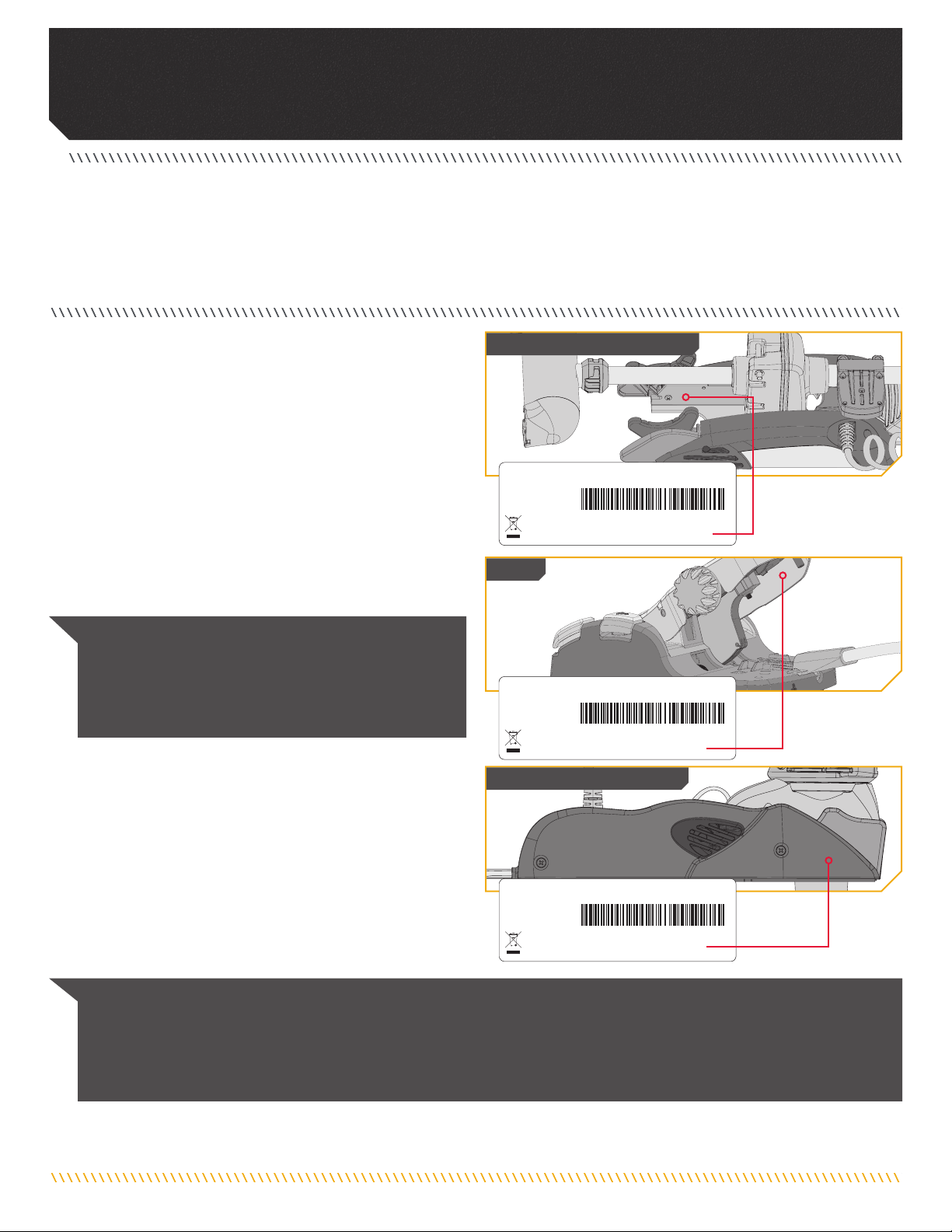
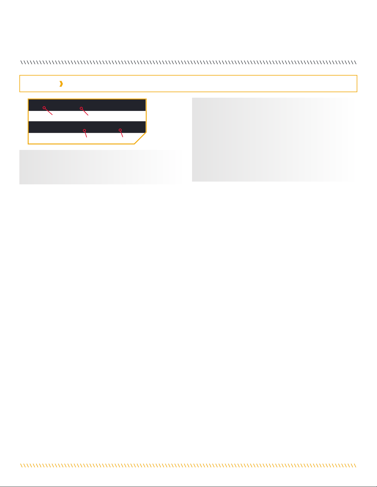
NOTICE: The motor serial number encompasses the
i-Pilot Link navigation system. The location of the serial
number, is in a different location based on the motor
model it is installed on. Refer to the images to the right
to determine location based on motor model.
Terrova & Riptide Terrova
Ultrex
Ulterra & Riptide Ulterra

minnkotamotors.com | 3
©2019 Johnson Outdoors Marine Electronics, Inc.
Table Of CONTeNTs
SAFETY CONSIDERATIONS ............................................................... 4
WARRANTY................................................................................... 5
FEATURES..................................................................................... 6
REMOTE BUTTONS ......................................................................... 7
REMOTE NAVIGATION...................................................................... 8
Using the i-Pilot Link Remote ................................................ 8
Touch Screen and Control Buttons ......................................... 9
Humminbird Control ............................................................. 9
The Options Menu and the System Menu.............................. 10
The Talon Menus ................................................................ 11
DISPLAY SCREEN ......................................................................... 12
GETTING STARTED........................................................................ 20
The i-Pilot Link System ....................................................... 20
System Startup................................................................... 21
Connect i-Pilot Link to the Humminbird........................ 21
Power Up the i-Pilot Link System ................................. 22
Charging the Remote Battery ....................................... 24
AUDIO MODES ............................................................................. 25
Understanding Audio Modes ................................................ 25
Audio Mode Control ............................................................ 26
Changing the Controller Audio Mode............................. 26
SPOT-LOCK ................................................................................. 27
How Spot-Lock Works ......................................................... 27
Engaging Spot-Lock .................................................... 28
Disengaging Spot-Lock................................................ 29
Go To a Saved Spot-Lock ............................................. 29
Disengage Go To Spot-Lock ......................................... 30
Spot-Lock Jog............................................................. 31
WAYPOINTS ................................................................................ 33
Working with Waypoints....................................................... 33
Mark a Waypoint ......................................................... 34
Go To a Saved Waypoint .............................................. 34
Disengage Go To Waypoint........................................... 35
CRUISE CONTROL......................................................................... 36
i-Pilot Link with Cruise Control............................................. 36
Engaging Cruise Control .............................................. 37
Disengage Cruise Control............................................. 38
HIGH SPEED BYPASS .................................................................... 39
Motor Speed and High Speed Bypass ................................... 39
Engaging High Speed Bypass....................................... 40
Disengaging High Speed Bypass .................................. 40
AUTOPILOT ................................................................................. 41
i-Pilot Link with Autopilot.................................................... 41
AutoPilot Modes ................................................................. 41
Engaging Legacy AutoPilot or Advanced AutoPilot ......... 42
Disengaging Legacy AutoPilot or Advanced AutoPilot ..... 43
To Set the Default AutoPilot Mode................................ 43
iTRACKS..................................................................................... 45
Understanding iTracks......................................................... 45
Recording an iTrack .................................................... 46
Go To a Saved iTrack .................................................. 47
Disengage Go To iTrack................................................ 48
Reverse Go To iTrack ................................................... 48
CIRCLE MODE .............................................................................. 49
Understanding Circle Mode ................................................. 49
Change the Radius of Circle Mode................................ 50
Reverse Direction with Circle Mode .............................. 50
Disengage Circle Mode................................................ 51
FOLLOW THE CONTOUR ................................................................. 52
Understanding Follow the Contour........................................ 52
Change the Offset with Follow the Contour.................... 53
Reverse Direction with Follow the Contour .................... 53
Disengage Follow the Contour ...................................... 54
ROUTES...................................................................................... 55
Understanding Routes......................................................... 55
Reverse the Direction of Route Navigation .................... 56
Disengage Route Navigation ........................................ 56
HEADING SENSOR ........................................................................ 57
Heading Sensor Features..................................................... 57
Installation......................................................................... 59
Working with the Heading Sensor ......................................... 64
Pairing the Heading Sensor .......................................... 64
Heading Sensor Calibration .......................................... 65
Heading Offset ............................................................ 68
MOTOR CONTROLS ....................................................................... 70
To Toggle the Prop Auto On.................................................. 70
Adjusting Boat Scale........................................................... 71
Deploying the Motor............................................................ 72
Stowing the Motor............................................................... 74
Adjusting the Trim .............................................................. 75
Change the Arrival Mode ..................................................... 77
TALON CONTROLS ........................................................................ 79
Talon Controls..................................................................... 79
Talon Options ..................................................................... 87
Talon System...................................................................... 94
REMOTE CONTROLS...................................................................... 98
To Adjust the Backlight ....................................................... 98
To Adjust the Backlight Timeout........................................... 99
Restore System Defaults.................................................... 100
Selecting Remote Language............................................... 101
Change the Depth Units .................................................... 102
Change the Distance Units ................................................ 103
Change the Speed Units.................................................... 104
Change the Temperature Units........................................... 105
Change the Time Format.................................................... 106
Change the Time Zone....................................................... 107
Toggle Daylight Savings ..................................................... 108
Change the Go To List Sort Order ....................................... 109
Set the Remote Auto Off ................................................... 110
To Lock the Remote .......................................................... 111
To Unlock the Remote....................................................... 112
To Rotate the Touch Screen ............................................... 112
To Toggle the Touch Screen ............................................... 113
To Edit the Home Screen Button Menu............................... 114
i-PILOT LINK APP ....................................................................... 116
Launching the App & Demo Mode...................................... 119
Getting Started................................................................. 120
Pairing the Device with the i-Pilot Link Controller ......... 120
Update the i-Pilot Link App ........................................ 121
Check Remote and Controller Software Version............. 122
Update the i-Pilot Link Controller................................ 123
SERVICE & MAINTENANCE........................................................... 124
To Open the Diagnostics Screen ......................................... 124
i-Pilot Link Software ......................................................... 125
To Open the About Screen .......................................... 125
Update i-Pilot Link Remote Software........................... 126
Pairing a Remote with a Controller .................................... 127
Talon Control ................................................................... 128
General Maintenance ....................................................... 132
Troubleshooting ................................................................ 132
For Further Troubleshooting & Repair ................................. 133
COMPLIANCE STATEMENTS.......................................................... 134
PARTS DIAGRAM & PARTS LIST .................................................... 136

4 | minnkotamotors.com ©2019 Johnson Outdoors Marine Electronics, Inc.
safeTY CONsIDeRaTIONs
Please thoroughly read the user manual. Follow all instructions and heed all safety and cautionary notices. Use of this product is only
permitted for persons that have read and understood these user instructions. Minors may use this product only under adult supervision.
WARNING
You are responsible for the safe and prudent operation of your vessel. We have designed your Minn Kota product to be an accurate
and reliable tool that will enhance boat operation and improve your ability to catch fish. This product does not relieve you from the
responsibility for safe operation of your boat. You must avoid hazards to navigation and always maintain a permanent watch so you can
respond to situations as they develop. You must always be prepared to regain manual control of your boat. Learn to operate your Minn
Kota product in an area free from hazards and obstacles.
WARNING
It is recommended to only use Johnson Outdoors approved accessories with your Minn Kota motor, such as this i-Pilot Link system.
Using non-approved accessories including to mount or control your motor may cause damage, unexpected motor operation and injury.
Be sure to use the product and approved accessories, including remotes, safely and in the manner directed to avoid accidental or
unexpected motor operation. Keep all factory installed parts in place including motor and accessory covers, enclosures and guards.
WARNING
When the motor is being controlled by the i-Pilot Link system, the Control Head will continue to perform the last task it was assigned,
even when the remote is not powered "on". Be sure to know how to power the motor "on" and "off", and always be alert for unexpected
motor movement, such as a turning propeller, even when the remote is powered "off". Refer to the Owner's Manual for how to control
the motor without the i-Pilot Link remote and become familiar with it's features including how to turn it "on" and "off".
CAUTION
This unit uses a magnetic compass to detect direction of travel. The compass can be adversely affected by magnets or large, ferrous
metal objects near (within 24” of) the trolling motor control head.
Obstructions on the propeller may cause excessive vibration of the motor head. This vibration can cause the compass to wander and
erratic steering to occur. Clear the obstruction to return the motor and i-Pilot Link system to normal operation.

minnkotamotors.com | 5
©2019 Johnson Outdoors Marine Electronics, Inc.
WaRRaNTY
WARRANTY ON MINN KOTA I-PILOT® AND I-PILOT® LINK™ WIRELESS GPS
TROLLING SYSTEM ACCESSORY
Johnson Outdoors Marine Electronics, Inc. (“JOME”) extends the following limited warranty to the original retail purchaser only. Warranty coverage is
not transferable.
Minn Kota Limited Two-Year Warranty on the Entire Product
JOME warrants to the original retail purchaser only that the purchaser’s new Minn Kota i-Pilot® or i-Pilot® Link™ Wireless GPS Trolling System
Accessory will be materially free from defects in materials and workmanship appearing within two (2) years after the date of purchase. JOME will (at its
option) either repair or replace, free of charge, any parts found by JOME to be defective during the term of this warranty. Such repair, or replacement
shall be the sole and exclusive liability of JOME and the sole and exclusive remedy of the purchaser for breach of this warranty.
Exclusions & Limitations
This limited warranty does not apply to products that have been used commercially or for rental purposes. This limited warranty does not cover normal
wear and tear, blemishes that do not affect the operation of the product, or damage caused by accidents, abuse, alteration, modification, shipping
damages, negligence of the user or misuse, improper or insufficient care or maintenance. DAMAGE CAUSED BY THE USE OF OTHER REPLACEMENT PARTS
NOT MEETING THE DESIGN SPECIFICATIONS OF THE ORIGINAL PARTS WILL NOT BE COVERED BY THIS LIMITED WARRANTY. The cost of normal maintenance or
replacement parts which are not in breach of the limited warranty are the responsibility of the purchaser. Prior to using products, the purchaser shall
determine the suitability of the products for the intended use and assumes all related risk and liability. Any assistance JOME provides to or procures
for the purchaser outside the terms, limitations or exclusions of this limited warranty will not constitute a waiver of the terms, limitations or exclusions,
nor will such assistance extend or revive the warranty. JOME will not reimburse the purchaser for any expenses incurred by the purchaser in repairing,
correcting or replacing any defective products or parts, except those incurred with JOME’s prior written permission. JOME’S AGGREGATE LIABILITY WITH
RESPECT TO COVERED PRODUCTS IS LIMITED TO AN AMOUNT EQUAL TO THE PURCHASER’S ORIGINAL PURCHASE PRICE PAID FOR SUCH PRODUCT.
How To Obtain Warranty Service
To obtain warranty service in the U.S., the product believed to be defective, and proof of original purchase (including the date of purchase), must
be presented to Minn Kota’s factory service center in Mankato, MN. Any charges incurred for service calls, transportation or shipping/freight to/from
the factory, labor to haul out, remove, re-install or re-rig products removed for warranty service, or any other similar items are the sole and exclusive
responsibility of the purchaser. Products purchased outside of the U.S. must be returned prepaid with proof of purchase (including the date of purchase
and serial number) to any Authorized Minn Kota Service Center in the country of purchase. Warranty service can be arranged by contacting the factory
at 1-800-227-6433 or email service@minnkotamotors.com. Products repaired or replaced will be warranted for the remainder of the original warranty period
[or for 90 days from the date of repair or replacement, whichever is longer]. For any product that is returned for warranty service that JOME finds to be not covered
by or not in breach of this limited warranty, there will be a billing for services rendered at the prevailing posted labor rate and for a minimum of at least one hour.
NOTICE: Do not return your Minn Kota product to your retailer. Your retailer is not authorized to repair or replace products.
NOTICE: THERE ARE NO EXPRESS WARRANTIES OTHER THAN THESE LIMITED WARRANTIES. IN NO EVENT SHALL ANY IMPLIED WARRANTIES INCLUDING ANY
IMPLIED WARRANTIES OF MERCHANTABILITY OR FITNESS FOR PARTICULAR PURPOSE, EXTEND BEYOND THE DURATION OF THE RELEVANT EXPRESS LIMITED
WARRANTY. IN NO EVENT SHALL JOME BE LIABLE FOR PUNITIVE, INDIRECT, INCIDENTAL, CONSEQUENTIAL OR SPECIAL DAMAGES. Without limiting the
foregoing, JOME assumes no responsibility for loss of use of product, loss of time, inconvenience or other damage.
Some states do not allow limitations on how long an implied warranty lasts or the exclusion or limitation of incidental or consequential damages, so the
above limitations and/or exclusions may not apply to you. This warranty gives you specific legal rights and you may also have other legal rights which
vary from state to state.

6 | minnkotamotors.com ©2019 Johnson Outdoors Marine Electronics, Inc.
feaTURes
Screen Navigation
Ok
Speed Up
Speed Down
Dashboard
Info Boxes
Touch Screen
Active Area
Prop On/Off
Steer Left Steer Right
Spot-Lock Home
i-PILOT® LINK™ REMOTE
Header
Talon
Display Screen
Content Area
Charge Indicator Light
NOTICE: Specifications subject to change without notice. This diagram is for reference only and may differ from your actual
product.
Control Head
Ulterra
Riptide Ulterra
Ultrex™
Terrova™
Riptide® Terrova™
Pair Button
i-PILOT® LINK™ CONTROL HEAD

minnkotamotors.com | 7
©2019 Johnson Outdoors Marine Electronics, Inc.
ReMOTe bUTTONs
NOTICE: If Steer Right or Steer Left is held down
for more than eight seconds, the steering will stop to
prevent the coil cord from wrapping around the shaft.
Home
Press to bring up the Home Screen Buttons.
Screen Navigation
Press to navigate the menu without touching the screen. Press and hold to lock and unlock the remote.
Ok
Press to accept menu selections. Press to power remote on. Press and hold for 3 seconds to power remote off.
Spot-Lock
Press to enable and disable Spot-Lock.
Speed Up & Speed Down
Press to increase or decrease motor speed.
Steer Left & Steer Right
Press to steer the motor to the left or to the right.
Prop On/Off
Pressing this button will turn the Prop on and off.
NOTICE: If your motor is connected to a Heading
Sensor, the Speed Down (backwards), Speed
Up (forward), Steer Right (right) and Steer Left
(left) buttons function change to Jog the boat while
in Spot-Lock.
NOTICE: The remote is waterproof, but will not float.
Ultrex™
Terrova™
Riptide® Terrova™
MENU CONTROL BUTTONS
MANUAL CONTROL BUTTONS
NAVIGATION BUTTONS
WARNING
The i-Pilot Link remote is equipped with a touch screen. Be aware of accidental or unintentional contact with the remote touch screen
in order to avoid accidental motor operation.

8 | minnkotamotors.com ©2019 Johnson Outdoors Marine Electronics, Inc.
ReMOTe NaVIGaTION
USING THE i-PILOT LINK REMOTE
The i-Pilot Link remote is equipped with a touch screen. Menus within the remote can be navigated using the buttons along the top of
the remote, or by selecting options using the touch screen. Many of the menus with the i-Pilot Link system require the user to scroll up
and down to view additional options in the Content Area. If it is preferred that the remote is only used with input from the top buttons,
the touch functionality can be turned off.
G
G
o
o
T
T
o
o
o
o
T
T
T
T
W
a
y
po
i
n
t
O
ptions
M
M
a
a
r
r
k
k
W
a
ypo
i
n
t
System
Ul
t
e
r
r
a
L
o
ckKeys
PROP SOG
mph
TEMP 73 °F DPTH 25 ftBRG 359°
12:53 PM
A
u
t
opi
l
ot
C
ru
i
se C
o
n
t
r
o
l
R
e
c
o
r
d
H
S
B
G
G
o
o
T
T
o
o
o
o
T
T
T
T
S
p
ot-
L
o
ck
G
G
o
o
T
T
o
o
o
o
T
T
T
T
i
T
r
a
c
k
G
G
G
o
o
T
T
T
o
o
o
o
T
T
T
S
pot-
L
o
ck
G
G
G
o
o
T
T
T
o
o
o
o
T
T
T
T
i
T
r
ac
k
WARNING
The i-Pilot Link remote is equipped with a touch screen. Be aware of accidental or unintentional contact with the remote touch screen
in order to avoid accidental motor operation.
minnkotamotors.com | 9
©2019 Johnson Outdoors Marine Electronics, Inc.
REMOTE NAVIGATION
NOTICE: Buttons may be made inactive while others
remain active. There are a number of reasons that Home
Screen Buttons may be inactive, including the remote not
being paired or communicating with the controller, a GPS
fix has not been made, the motor is stowed, or the Prop
is locked out.
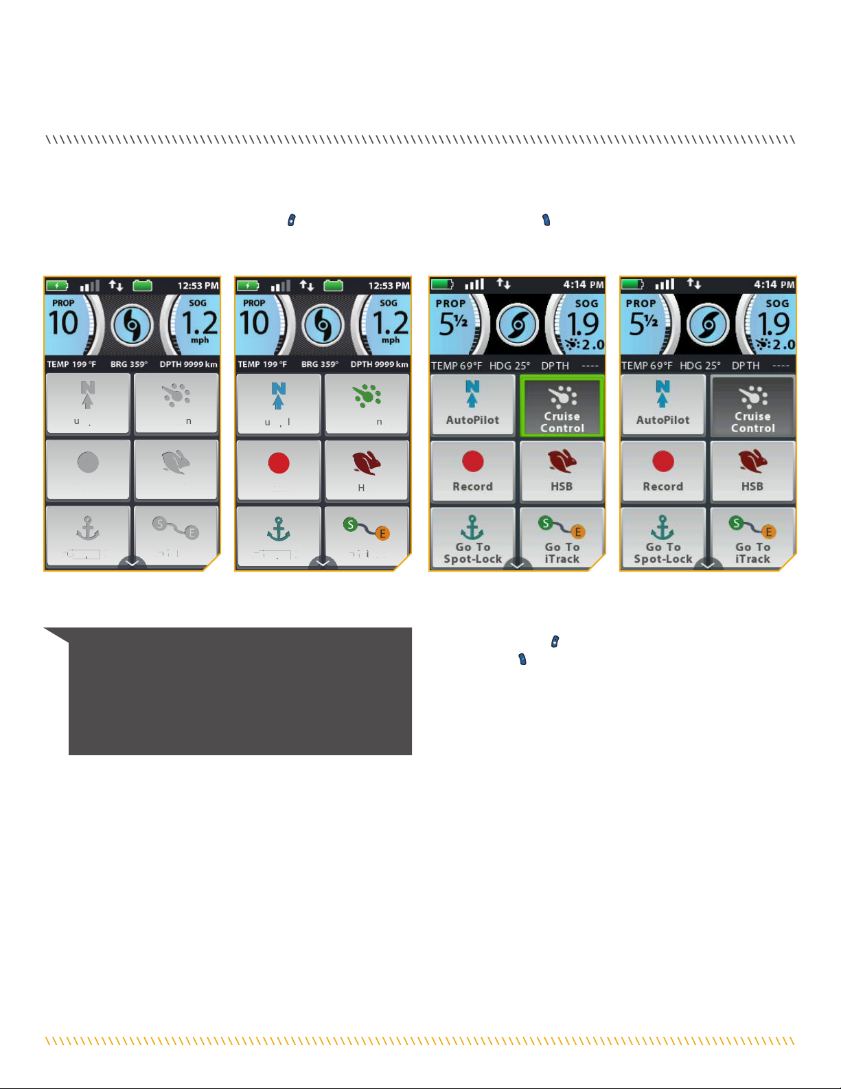
The i-Pilot Link remote can be controlled using the remote buttons, by utilizing the touch screen, or a combination of both. When using
the remote buttons, the Screen Navigation button will scroll through options and the Ok button is used to select options. There
is a green box highlighting selections when the buttons are used. The green selection box is not present when the screen is navigated
using touch.
TOUCH SCREEN AND CONTROL BUTTONS
PROP SOG
mph
TEMP 199 °F DPTH 9999 kmBRG 359°
12:53 PM
A
u
u
t
t
o
o
p
p
i
l
o
o
t
t
C
C
r
u
u
i
s
s
e
e
C
C
o
o
n
t
t
r
o
o
l
R
e
c
o
o
r
d
d
H
H
S
S
B
B
G
o
T
o
o
S
p
p
o
t
T
T
L
o
c
k
G
G
o
o
T
T
o
o
o
o
i
i
T
T
T
T
T
r
r
a
a
c
c
k
k
PROP SOG
mph
TEMP 199 °F DPTH 9999 kmBRG 359°
12:53 PM
A
u
u
t
t
o
o
p
p
i
l
o
o
t
t
C
C
r
u
u
i
s
s
e
e
C
C
o
o
n
t
t
r
o
o
l
R
e
e
c
c
o
o
r
d
d
H
H
S
S
B
B
G
o
T
o
o
S
p
p
o
t
T
T
L
o
ck
G
G
o
o
T
T
o
o
o
o
i
i
T
T
T
T
T
r
r
a
a
c
c
k
k
The Home Screen Buttons on
the touch screen are active.
The Home Screen Buttons on
the touch screen are disabled.
The Home Screen Buttons are
Active and the Cruise Control
button has been selected using
the Screen Navigation button
and then the Ok button.
The Home Screen Buttons are
Active and the Cruise Control
button has been selected using
the touch screen.
HUMMINBIRD CONTROL
Certain i-Pilot Link features can only be initiated from a compatible Humminbird fish finder. When the i-Pilot Link is connected to a
Humminbird, features such as Follow the Contour and Circle Mode can only be initiated from the Humminbird. Active Bands for these
functions can we viewed on the i-Pilot Link Remote, and minimal control can only be exercised over these functions from the remote. For
a full list of features and information on how to control the i-Pilot Link with the Humminbird, please see the Humminbird documentation.
For a list of Humminbird units and SD cards, that are compatible with i-Pilot Link, please visit minnkotamotors.com.
10 | minnkotamotors.com ©2019 Johnson Outdoors Marine Electronics, Inc.
REMOTE NAVIGATION
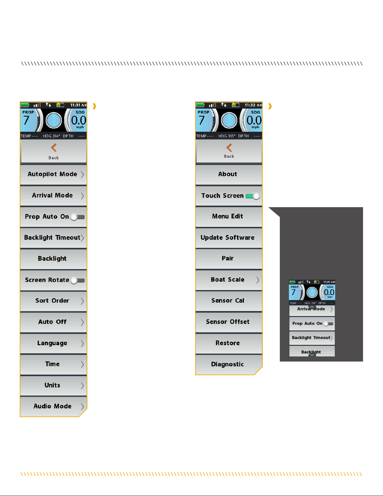
THE OPTIONS MENU AND THE SYSTEM MENU
Become familiar with the Options Menu and the System Menu to easily navigate controls within the i-Pilot Link System.
NOTICE: Arrows are
present on any menu when
the menu has more options
available. The arrows
appear when there are
more options either above
or below the currently
visible options.
The Options Menu is accessible by
selecting it from the Home Screen
Buttons. Become familiar with
the choices in the Options Menu
to better control the i-Pilot Link
system. Options Menu selections
include selecting the AutoPilot
Mode, Arrival Mode, Prop Auto
On, Backlight Timeout, Backlight,
Screen Rotation, Sort Order, Auto
Off, Language, Time, Units and
Audio Mode.
The System Menu is accessible by
selecting it from the Home Screen
Buttons. Become familiar with
the choices in the System Menu
to better control the i-Pilot Link
system. System Menu selections
include selecting About, Touch
Screen, Menu Edit, Update
Software, Pairing, Boat Scale,
Sensor Cal, Sensor Offset, Restore
and Diagnostics.
Options Menu System Menu

minnkotamotors.com | 11
©2019 Johnson Outdoors Marine Electronics, Inc.
REMOTE NAVIGATION
THE TALON MENUS
Become familiar with the Talon menus to easily control the Talon(s) within the i-Pilot Link System.
The Talon Menu is accessible by
selecting the Talon Button from
the Home Screen. The Talon Menu
brings up the Talon Dashboard as
well as additional settings that can
be used to control the Talon from
the i-Pilot Link System.
The Talon Options Menu is
accessible by first selecting Talon
from the Home Screen Buttons
and then selecting Talon Options.
Become familiar with the choices
in the Talon Options Menu to better
control the Talon(s) from the i-Pilot
Link system. Talon Options Menu
selections include Auto Retract,
Panel LED, Manual Mode and
Reverse L/R Talon.
The Talon System Menu is
accessible by first selecting Talon
from the Home Screen Buttons
and then selecting Talon System.
Become familiar with the choices
in the Talon System Menu to better
control the Talon(s) from the i-Pilot
Link system. Talon System Menu
selections include About, Touch
Screen, Menu Edit and Forget Talon.
Talon Menu Talon Options Menu
Talon System Menu
NOTICE: When the Talon Menu is displayed on the
i-Pilot Link remote, pressing the Spot-Lock , Prop ,
Steer Left , Steer Right , Speed Up or Speed
Down buttons changes the Display Screen to the
i-Pilot Link Home Screen.

12 | minnkotamotors.com ©2019 Johnson Outdoors Marine Electronics, Inc.
DIsPlaY sCReeN
t Only available with Ulterra. n Only available with Ultrex.
PROP SOG
mph
1.5
GPS Signal
Strength
Motor
Battery Time
Talon
Remote
Battery Humminbird
Connection
Motor Battery tn
Displays motor battery level when prop
is disengaged.
Time
Displays the current time.
Talon
Displays the connection with one or two Talons
and indicates if the Talon(s) are deployed. One Icon
will display in the event that one Talon is paired,
and two will display if two Talons are piared. The
icons will turn grey to indicate that the Talon(s) is
not connected.
Remote Battery
Displays the battery level of the remote.
GPS Signal Strength
Displays the level of GPS signal strength. If no bars
appear, or if the bars are flashing, the system has
not yet acquired a GPS fix.
Humminbird Connection
Displays white arrows to show when the i-Pilot Link
controller is communicating with the Humminbird.
Grey arrows indicate that there is
no communication.
Speed Over Ground
Displays the current speed over ground.
High Speed Bypass
Displays when High Speed Bypass is engaged.
Prop On/Off
Displays when the Prop is enabled. Rotates when
the Prop is on and the Prop Speed is greater than
zero. Blinks when a mode of navigation is used that
requires the prop to be enabled.
Cruise Control
Displays when Cruise Control is engaged along with
the Target Speed.
Prop Speed
Displays the current Prop Speed. Can be adjusted
in 1/2 speed increments between 0 and 10.
PROP SOG
PROP SOG
PROP SOG
PROP SOG
PROP SOG
Speed Over
Ground
Prop On/Off
Cruise
Control
Prop
Speed
High Speed
Bypass
HEADER
i-PILOT LINK DASHBOARD
minnkotamotors.com | 13
©2019 Johnson Outdoors Marine Electronics, Inc.
DISPLAY SCREEN
TEMP 65 °F DPTH 5 ftHDG 255°
TEMP 72 °F DPTH 1 ftBRG 359°
Temperature
The current water temperature based on
communication with the Humminbird.
Bearing
Bearing is the direction from the boat's current
location to the target destination during navigation.
Heading
Heading is the direction that the motor is pointing.
Depth
The current water depth based on communication
with the Humminbird.
Depth
Bearing
Temperature
Heading
TEMP 65 °F DPTH 5 ftHDG 255°
TEMP 72 °F DPTH 1 ftBRG 359°
TEMP 65 °F DPTH 5 ftHDG 255°
TEMP 72 °F DPTH 1 ftBRG 359°
TEMP 65 °F DPTH 5 ftHDG 255°
TEMP 72 °F DPTH 1 ftBRG 359°
TEMP 65 °F DPTH 5 ftHDG 255°
TEMP 72 °F DPTH 1 ftBRG 359°
INFO BOXES
14 | minnkotamotors.com ©2019 Johnson Outdoors Marine Electronics, Inc.
DISPLAY SCREEN
Rough Water Mode
In Rough Water Mode, the Mode LED Indicator on
the Indicator Panel will be lit red. In Rough Water
Mode, the Auto Deploy will operate with maximum
down-force with three Auto-Drive cycles of three
hits each, spaced 3 seconds apart. The three Auto-
Drive cycles will be spaced at 10 second intervals.
Soft Bottom Mode
In Soft Bottom Mode, the Mode Indicator LED will
be lit green on the Indicator Panel. In Soft Bottom
Mode, the Auto Deploy will operate at a reduced
power with a single hit. During calm conditions or
on water with muddy or soft sandy bottoms, Soft
Bottom Mode will prevent the Talon from
over-anchoring.
Talon Retracted
Indicates that the Talon is fully retracted.
Talon Anchored
Indicates the Talon is anchored
Manual Retract
Indicates that the Talon has been placed into
Manual Retract Mode. This may apply to the left,
right or both Talons.
Talon Selection - Both
Indicates both the Port and Starboard Talons are
selected and will be controlled while operating.
Press to toggle between left, right and both Talons.
This option is only seen when the remote is set up
to control two Talons.
Talon Selection - Left
Indicates the left Talon is selected and will be
controlled while operating. By default the left Talon
is the Port side Talon when multiple Talons are
installed and paired. This can be changed in the
Talon Options menu.
Talon Selection - Right
Indicates the right Talon is selected and will be
controlled while operating. By default, the right
Talon is the Starboard side Talon when multiple
Talons are installed and paired. This can be
changed in the Talon Options menu.
Standard Mode
Standard Mode is the default anchoring Mode
for Talon. In Standard Mode, Talon's Auto Deploy
will operate with maximum down-force with a
complete Auto-Drive cycle of three hits spaced at
three seconds apart. When put in Standard Mode,
the Mode Indicator LED in the Indicator Panel will
toggle between red and green and then turn off.
Talon
Status
Mode
Talon
Selection
Talon
Status
Depth
Indication Depth
Indication
TALON DASHBOARD
NOTICE: When the Talon Menu is displayed on the i-Pilot
Link remote, pressing the Spot-Lock , Prop , Steer
Left , Steer Right , Speed Up or Speed Down
buttons changes the Display Screen to the i-Pilot Link
Home Screen.
minnkotamotors.com | 15
©2019 Johnson Outdoors Marine Electronics, Inc.
DISPLAY SCREEN
Legacy AutoPilot
The AutoPilot button is used to engage and
disengage Legacy AutoPilot.
Advanced AutoPilot
The AutoPilot button is used to engage and
disengage Advanced AutoPilot.
Record
The Record button is used to start and stop
recording an iTrack.
HSB
Select the HSB (High Speed Bypass) button to
engage High Speed Bypass. High Speed Bypass
automatically sets the Prop speed to 10. Double
press to engage. Single press to disengage.
Lock Keys
Press and hold the Lock Keys button to lock the
buttons and touch screen. Pressing and holding the
Screen Navigation button also locks and unlocks
the remote buttons and touch screen.
Cruise Control
Press the Cruise Control button to enable or disable
Cruise Control. Once Cruise Control is enabled,
pressing the Speed Up or Speed Down
buttons will change the Target Speed rather than
the Prop Speed.
Mark Waypoint
Press to mark a Waypoint.
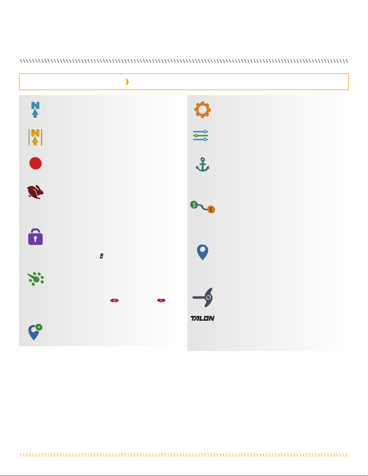
i-PILOT LINK HOME SCREEN BUTTONS
t Only available with Ulterra. n Only available with Ultrex.
System
Press the System button to open the System menu
and adjust settings within the i-Pilot Link system.
Options
Press the Options button to open the Options menu
and adjust options within the i-Pilot Link system.
Go To Spot-Lock
The Go To Spot-Lock button is used to open a
menu used to navigate to a Spot-Lock location. The
i-Pilot Link system will only bring up Spot-Locks
within a quarter mile range.
Go To iTrack
The Go To iTrack button is used to open a menu
used to navigate to an iTrack. The i-Pilot Link
system will only bring up iTracks within a quarter
mile range.
Go To Waypoint
The Go To Waypoint button is used to open a menu
used to navigate to a Waypoint location. The i-Pilot
Link system will only bring up Waypoints within a
quarter mile range.
Ulterra t
The Ulterra button is used to access functions
specific to controlling the Ulterra.
Talon
The Talon button is used to access functions
specific to controlling Talon(s) on the
i-Pilot System.

16 | minnkotamotors.com ©2019 Johnson Outdoors Marine Electronics, Inc.
DISPLAY SCREEN
Up
Retracts the active Talon(s). Will be replaced by
Pause as the action is taking place.
Down
Used to deploy the anchor. Must be double-pressed
to engage.
Pause
When pressed, it interrupts the current action.
The Talon(s) will remain at the current depth until
another command is sent. The action for both
deploying and retracting the anchor can be paused.
The pause button may appear in place of the Up or
Down buttons, during deploying or retracting and
will disappear when pressed while the unit
is paused.
Anchor Mode
Select the Anchoring Mode between Standard
Mode, Soft Bottom or Rough Water. The
appearance of the button and the icon in the
Talon Dashboard will change depending on the
Mode selected.
TALON MENU BUTTONS
i-Pilot
Select to return to the i-Pilot Link Menu.
Active Talon
Allows the user to selects the active Talon and can
be set to either, left, right or both. The appearance
of the button and the icon in the Talon Dashboard
will change depending on the Talon selected and
the condition of how many Talons are paired to
the system.
Talon Work Light
Press to gain access to the Work Light
options including selecting the Work Light color
and intensity.
Talon Options Menu
Press to open the Talon Options Menu.
Talon System Menu
Press to open the Talon System Menu.
NOTICE: The buttons in the Talon Menu may become
inactive if the Talon is not connected or communication
with the i-Pilot Link System.

minnkotamotors.com | 17
©2019 Johnson Outdoors Marine Electronics, Inc.
DISPLAY SCREEN
Home
Press to go to the Home Screen.
Back
Select to go back to the previous screen.
Cancel
Select to cancel current action.
Sort Order
Select to change the sort order of a Go To list. Lists
can be sorted by distance, time, or alphabetically
by name.
Update/Restore
Press to run an update when in the Update Software
menu. Updates done from the remote are to update
the remote. When in the Restore menu, press to
restore the i-Pilot Link's factory settings.
Increase/Add
Press to increase when making an adjustment
such as increasing screen brightness or adjusting
course offset.
Decrease/Minus
Press to decrease when making an adjustment
such as decreasing screen brightness or adjusting
course offset.
To Start
When navigating an iTrack, select to navigate to the
start of the iTrack.
To End
When navigating an iTrack, select to navigate to the
end of the iTrack.
Set
Select to set the Heading Sensor offset.
Start
Select to start the Heading Sensor
Calibration process.
Trim Up t
Used to Trim the motor up.
Trim Down t
Used to Trim the motor down.
Save
When editing the menu, select to save the
menu layout.
Save
Select to save a temporary Spot-Lock.
Reverse
Select to reverse the direction of navigation, such as
when navigating an iTrack or Route.
Forward
Used to navigate forward. Such as in Spot-Lock Jog.
Right
Used to navigate to the right. Such as in
Spot-Lock Jog.
Back
Used to navigate back. Such as in Spot-Lock Jog.
Left
Used to navigate to the left. Such as in
Spot-Lock Jog.
Pause
Pause will suspend the current mode of navigation
when Spot-Lock is enabled, and can be resumed from
the Spot-Lock. Record, Follow the Contour, Routes,
iTracks and Circle Mode always pause. GoTo Spot-
Lock, GoTo Waypoint and HSB never pause. AutoPilot
and Cruise will only pause when running concurrently
with other modes that always pause.
Resume
Press to resume the initial navigational function.
Stop and Save iTrack
Select to stop and save an iTrack that is
being recorded.
t Only available with Ulterra. n Only available with Ultrex.
INTERFACE ICONS
18 | minnkotamotors.com ©2019 Johnson Outdoors Marine Electronics, Inc.
DISPLAY SCREEN
Active Bands appear on the i-Pilot Link remote any time a navigational function is engaged. They are designed to tell more about how
the system is functioning and display information to the user that is helpful in navigation. Active Bands are slightly different depending
on the type of navigation that is being executed. Become familiar with the most common Active Bands.
Legacy AutoPilot
Appears when AutoPilot is engaged and the default AutoPilot Mode is set to Legacy. Selecting the
contextual band will allow you to toggle between AutoPilot modes.
Advanced AutoPilot
Appears when AutoPilot is engaged and the default AutoPilot Mode is set to Advanced. Selecting the
contextual band will allow you to toggle between AutoPilot modes.
Go To iTrack
Appears when an iTrack is being navigated. Variations of this contextual band may show the position of
the boat, a distance, and the To Start and To End locations reversed.
Go To Spot-Lock
Appears when you Go To a Spot-Lock location and the Spot-Lock location is more that 100 feet from
the current location. Variations of this contextual band may show the position of the boat, a distance
and the Spot-Lock icon.
Go To Waypoint/Follow the Route
Appears when you follow a route or Go To a Waypoint. Variations of this contextual band may show the
position of the boat, a distance, and label end points as a Waypoint or Spot-Lock.
Record
Appears when an iTrack is being recorded. Variations show progress along the maximum length of an
iTrack and the distance that is recorded.
Follow the Contour
Appears when Follow the Contour is being navigated. It is initiated by the Humminbird. Variations show
the depth of the contour and the distance the boat is offset from the contour.
Circle Mode
Appears when Circle Mode is being navigated. It is initiated by the Humminbird. Variations show the
depth of the contour and the distance the boat is offset from the contour.
Routes
Appears when a Route is being navigated. It is initiated by the Humminbird. Variations show the depth
of the contour and the distance the boat is offset from the contour.
Spot-Lock
Appears when Spot-Lock is engaged. Variations include the distance from the Spot-Lock, a boat icon, a
pause icon, and the a save icon.
iTrack - Start
iTrack - Middle
iTrack - End
1 mi
IT0000000006
S
E
1.2 mi
IT0000000006
S
E
iTrack - From End to Start
1 mi
IT0000000006
E
0 ft
IT0000000006
S
E
Autopilot
Advanced
Autopilot
Legacy
Legacy Autopilot
Advanced Autopilot
163 ft
IT0000200163
Record
GoTo Route
100 ft
FR0007000002
Follow Route- Start
Follow Route - Middle
Follow Route - End
100 ft
FR0007000002
100 ft
FR0007000002
100 ft
FR0007000002
GoTo Waypoint
50 ft
WP0000000001
Folllow Contour Alt
S
Contour: xxxft
S
E
Go To iTrack
Go To SpotLock
Follow Route / GoTo Waypoint
Record
GoTo SpotLock
100 ft
SL0000000163
SpotLock 100 ft
SpotLock 40ft
SpotLock Paused 1
Green Boreder 1
100 ft
SL0000000163
1
00
f
t
S
S
S
S
S
S
L
L
L
0
0
0
0
0
0
0
0
0
0
0
0
0
0
0
0
0
0
0
0
0
1
1
1
6
6
6
3
3
3
Green Border 2
Distance
100 ft
SL0000000163
Distance
100 ft
SL0000000163
Distance
40 ft
SL0000000163
Distance
40 ft
SL0000000163
D
D
D
i
stan
c
e
4
4
4
4
0
f
t
S
S
S
S
S
S
L
L
L
L
L
0
0
0
0
0
0
0
0
0
0
0
0
0
0
0
0
0
0
0
0
0
0
0
0
0
0
0
0
0
0
0
0
0
0
0
1
1
1
1
1
6
6
6
6
6
3
3
3
3
3
ACTIVE BANDS

minnkotamotors.com | 19
©2019 Johnson Outdoors Marine Electronics, Inc.
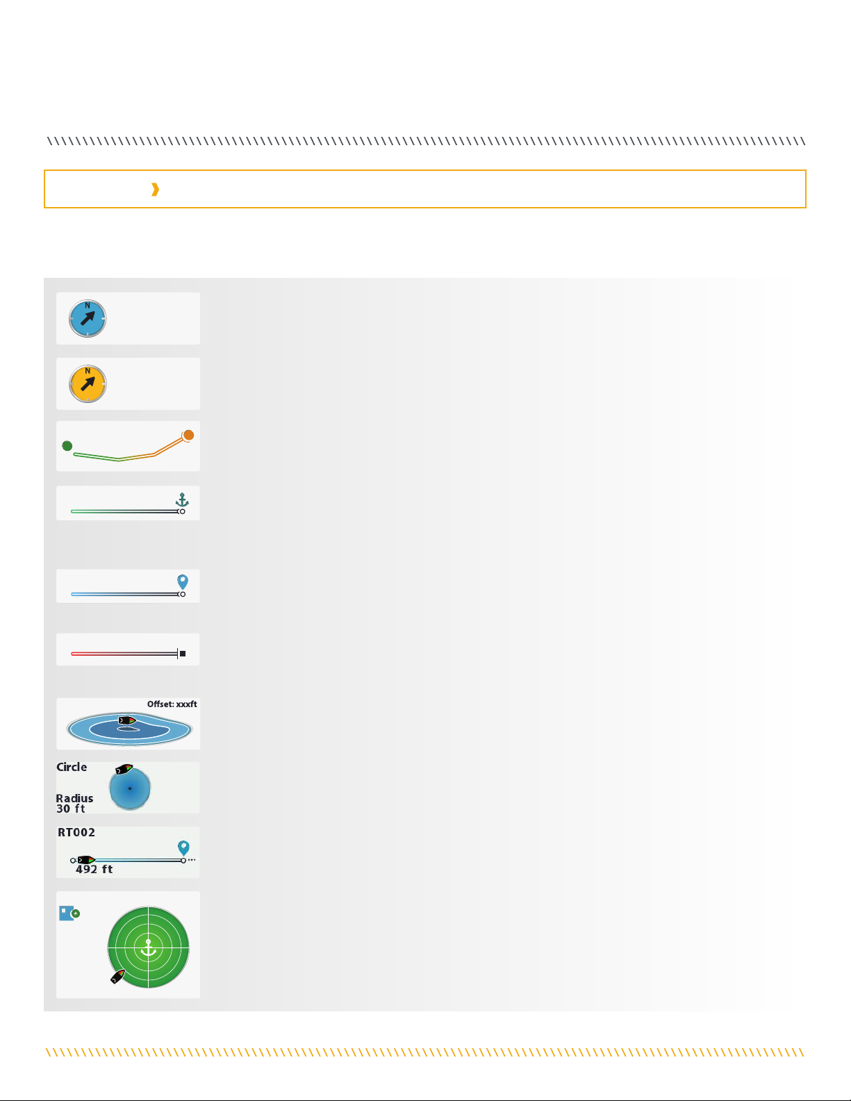
DISPLAY SCREEN
The Advanced AutoPilot Active
Band appears when Advanced
AutoPilot is engaged.
The Record iTrack Active
Band appears while a recording
is in progress. The boat has
traveled 209 feet during the
current recording.
The Spot-Lock Active Band
appears when Spot-Lock is
engaged. The Save icon indicates
that the Spot-Lock has not yet
been saved.
The iTrack Active Band appears
when a Go To iTrack action is
taking place. The current To
Start location on the iTrack
being navigated is 0.21 statute
miles away.
The Go To Spot-Lock Active
Band appears when the boat is
navigating to a saved Spot-Lock.
The Spot-Lock being navigated to
is 204 feet away.
The Follow the Contour Active
Band appears when the boat
is navigating with Follow the
Contour. The Contour being
followed is 10 feet. The Offset is
set to 0 feet.
The Go To Waypoint Active
Band appears when the boat is
navigating to a saved Waypoint.
The Waypoint 1282 is 163
feet away.
The Circle Mode Active band
appears when the navigation is
set to Circle Mode. The current
circle radius is set to 30 feet.
Sample Active Bands
Become familiar with some of the active bands used on the i-pilot link remote interface.

20 | minnkotamotors.com ©2019 Johnson Outdoors Marine Electronics, Inc.
GeTTING sTaRTeD
THE i-PILOT LINK SYSTEM
The i-Pilot Link navigation system comes pre-installed on your trolling motor. If your system comes with a Heading Sensor, the Heading
Sensor needs to be installed and paired with the i-Pilot Link controller. The i-Pilot Link controller is contained in the motor Control
Head. Please see the "Heading Sensor" portion of this manual for more information on the Heading Sensor. The i-Pilot Link remote also
comes paired to the controller from the factory. The i-Pilot remote and controller make up the i-Pilot Link navigation system. The top
of the motor Control Head also has a single Pair button to allow additional remotes and the Heading Sensor to be paired to the system.
A remote can only be paired with one controller at a time. The i-Pilot Link controller contains a very sensitive compass and is where all
GPS satellite and i-Pilot Link remote signals are received. Before
each startup, it is recommended to inspect the Remote, Propeller,
and Control Head for damage and to make sure that there are no
obstructions that would affect communication between the
Control Head, the GPS signal and the Remote, or boat movement.
Variable Effect
Ratio of motor thrust to boat weight Excessive thrust on a smaller boat can cause i-Pilot to over correct. Not enough thrust on a
large boat can cause i-Pilot to respond slowly.
Wind Excessive wind and/or current can reduce i-Pilot’s positioning accuracy.
GPS signal strength The greater number of GPS signal bars the greater the accuracy.
Trolling motor battery power level A fully charged battery will give the best performance.
The i-Pilot Link Control Head will turn on whenever the trolling
motor has power. Refer to the Owner's Manual for your specific
motor to determine how to power up your trolling motor.
Owner's Manuals can be found online at minnkotamotors.com.
It is recommended to turn off and disconnect the power source
from the trolling motor when not in use.
i-Pilot Link uses GPS satellite signals as well as digital compass data to know where it is, where its heading and the direction the motor is
pointing. Since i-Pilot Link depends on GPS satellite signals for navigation, a minimum GPS signal of one bar is required in order for GPS
navigation controls to be enabled. Best results are achieved when GPS signals of four bars can be obtained.
NOTICE: It is very important that the controller have a
clear view of the sky in all directions and has a clear line
of sight to the remote for optimum performance.
Remote Front
Speed Up
Button
Do Not Obstruct
Power
Navigation
Range
Accuracy
The accuracy and responsiveness with which i-Pilot Link
controls your boat is highly dependent upon many variables.
Just a few of these variables and their general effects on
responsiveness and accuracy are given below so that the
behavior of the system can be understood.
CAUTION
This unit uses a magnetic compass to detect direction of travel.
The compass can be adversely affected by magnets or large,
ferrous metal objects near (within 24” of) the trolling motor
control head.
Obstructions on the propeller may cause excessive vibration
of the motor head. This vibration can cause the compass to
wander and erratic steering to occur. Clear the obstruction to
return the motor to normal operation.
Power should be disconnected from the motor when not in use.
Removing the motor from the power source will ensure that
current is not reaching the electronics when not in use.
The range of the remote will be greatly reduced if it is used
near or mounted to any metal object including aluminum or
steel. It is also recommended that the front end of the remote,
near the Speed Up button, not be obstructed during use.
Other manuals for i-Pilot Link
10
Table of contents
Other MINN KOTA Control System manuals


