MINN KOTA i-Pilot Link User manual

INTEGRATED WIRELESS GPS TROLLING SYSTEM
USER MANUAL
https://www.boat-manuals.com/

© 2012 Johnson Outdoors Marine Electronics, Inc.
TABLE OF CONTENTS
Introduction.........................................................................................................................................................3
Warranty and Warnings...............................................................................................................................4-5
Installation .................................................................................................................................................... 6-25
Parts List....................................................................................................................................................6-7
Preparing for Installation ........................................................................................................................8
Installation of i-Pilot Link ................................................................................................................. 9-25
Getting Started..........................................................................................................................................26-37
Knowing Your Remote ....................................................................................................................26-27
Settings Menu....................................................................................................................................28-31
Controls Menu ......................................................................................................................................... 32
Remote Battery........................................................................................................................................ 33
Controller Operations .....................................................................................................................33-35
System Startup ........................................................................................................................................ 35
Software Updates.............................................................................................................................36-37
i-Pilot Setup ................................................................................................................................................38-41
Manual Control..........................................................................................................................................42-43
GPS Motor Control ..................................................................................................................................44-83
Spot-Lock.............................................................................................................................................48-53
Waypoints............................................................................................................................................54-57
iTracks ...................................................................................................................................................58-63
BackTrack .............................................................................................................................................64-65
Follow The Contour..........................................................................................................................66-69
Route Navigation..............................................................................................................................70-72
AutoPilot /Advanced AutoPilot....................................................................................................73-78
Cruise Control .......................................................................................................................................... 79
Data Management ...........................................................................................................................80-83
Frequently Asked Questions.................................................................................................................84-85
Troubleshooting .......................................................................................................................................86-87
Glossary.............................................................................................................................................................. 88
Compliance Statements............................................................................................................................... 89
Notes.............................................................................................................................................................90-91
23
INTRODUCTION
Overview
Thank you for purchasing the Minn Kota i-Pilot®Link™. This revolutionary boat control system enables your Minn Kota®
trolling motor and your Humminbird®Fishnder to communicate with each other, delivering unprecedented levels of
automatic navigation. Find, store, and revisit your most productive shing spots and tracks, taking control of it all from
either the i-Pilot Link wireless remote control or directly from the Humminbird Fishnder. Add an i-Pilot compatible
LakeMaster®digital map card and unlock the ability to automatically follow depth contours for even higher levels of boat
control. All with GPS accuracy so you spend less time positioning your boat and more time catching sh.
This i-Pilot Link Owner’s Manual is divided into four main sections: Installation, Getting Started, Manual Control, and GPS
Motor Control. A waterproof and easy-to-read Quick Reference Guide is included as a supplement to the User Manual.
A French version of the manual is available online at minnkotamotors.com
Une version français du manuel est disponible en ligne à minnkotamotors.com
Safety and Cautions while using Link
You are responsible for the safe and prudent operation of your vessel. We have designed i-Pilot Link to be an accurate and
reliable tool that will enhance boat operation and improve your ability to catch sh. This product does not relieve you from
the responsibility for safe operation of your boat. You must avoid hazards to navigation and always maintain a permanent
watchsoyoucanrespondtosituationsastheydevelop. Youmustalwaysbepreparedtoregainmanualcontrolofyourboat.
Learn to operate your i-Pilot Link in an area free from hazards and obstacles.
Warranty and Registration
To receive all the benets of your product warranty please ll out and mail the warranty registration card. You may also
register your product online at minnkotamotors.com.
Correctly installing i-Pilot Link on a Minn Kota trolling motor will not void the original motor warranty or the warranty of
any previously installed accessories. Installing i-Pilot Link will not extend the warranty of any Minn Kota product it is being
installed into or in conjunction with.
TRADEMARKS
Minn Kota®, Riptide®, i-Pilot®, AutoPilot™, CoPilot™, Link™, PowerDrive™, Terrova™ are trademarked by or registered
trademarks of Johnson Outdoors Marine Electronics, Inc.
2377156 Rev A
https://www.boat-manuals.com/

HUMMINBIRD WARNINGS
WARNING! This device should not be used as a navigational aid to prevent collision, grounding, boat damage, or personal
injury.Whenthe boatis moving,waterdepthmaychangetooquicklytoallowtimeforyoutoreact.Alwaysoperatethe boat
at very slow speeds if you suspect shallow water or submerged objects.
WARNING! The electronic chart in your Humminbird®unit is an aid to navigation designed to facilitate the use of autho-
rized government charts, not to replace them. Only ocial government charts and notices to mariners contain all of the
current information needed for the safety of navigation, and the captain is responsible for their prudent use.
WARNING! Humminbird®is not responsible for the loss of data les (waypoints, routes, tracks, groups, recordings, etc.)
that may occur due to direct or indirect damage to the unit’s hardware or software. It is important to back up your control
head’s data les periodically. Data les should also be saved to your PC before restoring the unit’s defaults or updating the
software. See your Humminbird®online account at humminbird.com and the Waypoint Management Guide on your
Humminbird®Manual CD for details.
WARNING! Do not travel at high speed with the unit cover installed. Remove the unit cover before traveling at speeds
above 20 mph.
WARNING! Disassembly and repair of this electronic unit should only be performed by authorized service personnel. Any
modicationoftheserialnumberorattempttorepairtheoriginalequipmentoraccessoriesbyunauthorizedindividualswill
void the warranty.
WARNING! This product contains chemicals known to the State of California to cause cancer and/or reproductive harm.
ATTENTION INTERNATIONAL CUSTOMERS: Products sold in the U.S. are not intended for use in the international
market. Humminbird®international units provide international features and are designed to meet country and regional
regulations.Languages,maps,timezones,unitsofmeasurement,andwarrantyareexamplesoffeaturesthatarecustomized
for Humminbird®international units purchased through our authorized international distributors. To obtain a list of
authorized international distributors, please visit our Web site at humminbird.com or contact our Customer Resource
Center at (334) 687-6613.
NOTE: The illustrations in this manual may not look the same as your product, but your unit will function in the same way.
NOTE: Some features discussed in this manual require a separate purchase, and some features are only available on
international models. Every eort has been made to clearly identify those features. Please read the manual carefully in
order to understand the full capabilities of your model.
NOTE: To purchase accessories for your control head, visit our Web site at humminbird.com or contact our Customer
Resource Center at 1-800-633-1468.
NOTE:The procedures and features described in this manual are subject to change without notice.This manual was written
in English and may have been translated to another language. Humminbird®is not responsible for incorrect translations or
discrepancies between documents.
NOTE: Product specications and features are subject to change without notice.
NOTE: Humminbird®veries maximum stated depth in saltwater conditions, however actual depth performance may vary
due to transducer installation, water type, thermal layers, bottom composition and slope.
NOTE: The maximum number of iTracks, Spot-Locks, waypoints, routes, and tracks may vary due to the setup of your
Waypoint Management directory. Groups and sub-groups also use storage, and the storage limit is inuenced by the
complexity of your Waypoint Management directory. See your Waypoint Management Guide for details.
TRADEMARKS
700 Series™, 800 Series™, 900 Series™, 1100 Series™, HumminbirdPC™, Humminbird®, LakeMaster®, Side Imaging®,
and X-Press™ Menu are trademarked by or registered trademarks of Johnson Outdoors Marine Electronics, Inc.
LIMITED TWOYEAR WARRANTY ON ENTIRE
IPILOT LINK PRODUCT:
Johnson Outdoors Inc. warrants to the original purchaser that the purchaser’s entire i-Pilot Link System®accessory is free
fromdefectsinmaterialsandworkmanshipappearingwithintwo(2)yearsafterthedateofpurchase.JohnsonOutdoorsInc.
will, at its option, either repair or replace, free of charge, any parts found to be defective during the term of this warranty.
Such repair or replacement shall be the sole and exclusive liability of Johnson Outdoors Inc. and the sole and exclusive
remedy of the purchaser for breach of this warranty.
These limited warranties do not apply to i-Pilot Link Systems used commercially, nor do they cover normal wear and tear,
blemishes that do not aect the operation, or damage caused by accidents, abuse, alteration, modication, misuse or
improper care or maintenance. DAMAGE CAUSED BY THE USE OF OTHER REPLACEMENT PARTS NOT MEETING THE
DESIGN SPECIFICATIONS OF THE ORIGINAL PARTS WILL NOT BE COVERED BY THIS LIMITED WARRANTY. The cost
of normal maintenance or replacement parts that are not defective are the responsibility of the purchaser.
To obtain warranty service in the U.S., the part believed to be defective and proof of original purchase (including the date of
purchase) must be presented to a Minn Kota Authorized Service Center or to Minn Kota’s factory service center in Mankato,
MN. Any charges incurred for service calls, transportation or shipping/freight to/from the Minn Kota Authorized Service
Center or factory, labor to haul out, remove, re-install or re-rig products removed for warranty service, or any other similar
itemsarethesole and exclusiveresponsibilityof the purchaser. i-PilotLink systemspurchasedoutsideof the U.S.(orparts of
such systems) must be returned prepaid with proof of purchase (including the date of purchase and serial number) to any
Authorized Minn Kota Service Center in the country of purchase. Warranty service can be arranged by contacting a
Minn Kota Authorized Service Center listed on the enclosed sheet or by contacting the factory at 1-800-227-6433,
1-507-345-4623 or fax 1-800-527-4464. Note: Do not return your i-Pilot Link or parts to your retailer. Your retailer is
not authorized to repair or replace them.
THERE ARE NO EXPRESS WARRANTIES OTHER THAN THESE LIMITED WARRANTIES. IN NO EVENT SHALL ANY
IMPLIED WARRANTIES, INCLUDING ANY IMPLIED WARRANTIES OF MERCHANTABILITY OR FITNESS FOR
PARTICULAR PURPOSE, EXTEND BEYOND TWO YEARS FROM THE DATE OF PURCHASE. IN NO EVENT SHALL
JOHNSON OUTDOORS MARINE ELECTRONICS L.L.C. BE LIABLE FOR INCIDENTAL, CONSEQUENTIAL OR
SPECIAL DAMAGES.
Some states do not allow limitations on how long an implied warranty lasts or the exclusion or limitation of incidental or
consequential damages, so the above limitations and/or exclusions may not apply to you.This warranty gives you specic
legal rights, and you may also have other legal rights which vary from state to state.
“WARNING: This product contains chemical(s) known to the state of California to cause cancer and/or
reproductive toxicity.”
HUMMINBIRD WARRANTY AND REGISTRATION
Please refer to your Humminbird product manual for details.
45
https://www.boat-manuals.com/

6 7
minnkotamotors.com
minnkotamotors.com
INSTALLATION INSTALLATION
PARTS LIST VIEW TERROVA & RIPTIDE ST PARTS LIST VIEW POWERDRIVE V2 & RIPTIDE SP
ITEM
#
PART
NUMBER DESCRIPTION QTY
TERROVA
1 2990280 HEAD ASSY,TERROVA, IP2 1
2 2994180 REMOTE ASSY, i-PILOT LINK 1
3 2370712 BATTERY, LIPO PACK 1
4 2374637 O-RING, BATTERY SEAL 1
5 2376421 DOOR, BATTERY 1
6 2383442 SCREW-3MM X .5 PPH MACHINE 4
7 2994907 BAG ASSY, i-PILOT LINK,TRRV 1
8 2372100 SCREW-#8-18 X 5/8 THD* (SS 4
9 2370817 LANYARD,RMT w/CARABINER 1
10 2224704 INSERT-PLUG, BLK, i-PILOT LINK 1
11 2376312 TIE WRAP,BLACK,UV RESIST.
NYLON
5
12 2994909 BAG ASSY, i-PILOT LINK, POWER 1
13 2373241 CABLE, USB REMOTE CHARGER 1
14 2375900 ADAPTER, USB POWER PORT 1
15 2377156 MANUAL-CD, i-PILOT LINK 1
16 2377155 MANUAL QCK REF, i-PILOT LINK 1
17 2320203 CAP-DUST,CONNECTOR,FEMALE 1
18 490389-1 CABLE, ETH (M12-M-M12-F, 30’ 1
RIPTIDE ST
1 2990281 HEAD ASSY, ST, IP2 1
2 2994180 REMOTE ASSY, i-PILOT LINK 1
3 2370712 BATTERY, LIPO PACK 1
4 2374637 O-RING, BATTERY SEAL 1
5 2376421 DOOR, BATTERY 1
6 2383442 SCREW-3MM X .5 PPH MACHINE 4
7 2994907 BAG ASSY, i-PILOT LINK,TRRV 1
8 2372100 SCREW-#8-18 X 5/8 THD* (SS 4
9 2370817 LANYARD,RMT w/CARABINER 1
10 2224704 INSERT-PLUG, BLK, i-PILOT LINK 1
11 2376312 TIE WRAP,BLACK,UV RESIST.
NYLON
5
12 2994909 BAG ASSY, i-PILOT LINK, POWER 1
13 2373241 CABLE, USB REMOTE CHARGER 1
14 2375900 ADAPTER, USB POWER PORT 1
15 2377156 MANUAL-CD, i-PILOT LINK 1
16 2377155 MANUAL QCK REF, i-PILOT LINK 1
17 2320203 CAP-DUST,CONNECTOR,FEMALE 1
18 490389-1 CABLE, ETH (M12-M-M12-F, 30’ 1
ITEM
#
PART
NUMBER DESCRIPTION QTY
POWERDRIVE V2
1 2990282 HEAD ASSY, V2, IP2 1
2 2994180 REMOTE ASSY, i-PILOT LINK 1
3 2370712 BATTERY, LIPO PACK 1
4 2374637 O-RING, BATTERY SEAL 1
5 2376421 DOOR, BATTERY 1
6 2383442 SCREW-3MM X .5 PPH MACHINE 4
7 2994908 BAG ASSY, i-PILOT LINK, V2 1
8 2372100 SCREW-#8-18 X 5/8 THD* (SS 4
9 2370817 LANYARD,RMT w/CARABINER 1
10 2376716 PLUG, STRAIN RELIEF V2/SP 1
11 2332104 SCREW-1/4-20 X 5/8 S/S 2
12 2376312 TIE WRAP,BLACK,UV RESIST.
NYLON
5
13 2375403 HEATSHRK .375X2 ADHV LINED 4
14 2994909 BAG ASSY, i-PILOT LINK, POWER 1
15 2373241 CABLE, USB REMOTE CHARGER 1
16 2375900 ADAPTER, USB POWER PORT 1
17 2377156 MANUAL-CD, i-PILOT LINK 1
18 2377155 MANUAL QCK REF, i-PILOT LINK 1
19 490389-1 CABLE, ETH (M12-M-M12-F, 30’ 1
RIPTIDE SP
1 2990283 HEAD ASSY, SP, IP2 1
2 2994180 REMOTE ASSY, i-PILOT LINK 1
3 2370712 BATTERY, LIPO PACK 1
4 2374637 O-RING, BATTERY SEAL 1
5 2376421 DOOR, BATTERY 1
6 2383442 SCREW-3MM X .5 PPH MACHINE 4
7 2994908 BAG ASSY, i-PILOT LINK, V2 1
8 2372100 SCREW-#8-18 X 5/8 THD* (SS 4
9 2370817 LANYARD,RMT w/CARABINER 1
10 2376716 PLUG, STRAIN RELIEF V2/SP 1
11 2332104 SCREW-1/4-20 X 5/8 S/S 2
12 2376312 TIE WRAP,BLACK,UV RESIST.
NYLON
5
13 2375403 HEATSHRK .375X2 ADHV LINED 4
14 2994909 BAG ASSY, i-PILOT LINK,POWER 1
15 2373241 CABLE, USB REMOTE CHARGER 1
16 2375900 ADAPTER, USB POWER PORT 1
17 2377156 MANUAL-CD, i-PILOT LINK 1
18 2377155 MANUAL QCK REF, i-PILOT LINK 1
19 490389-1 CABLE, ETH (M12-M-M12-F, 30’ 1
https://www.boat-manuals.com/
8 9
minnkotamotors.com
minnkotamotors.com
INSTALLATION INSTALLATION
FIGURE 1
FIGURE 2
FIGURE 3
PREPARING FOR INSTALLATION
For PowerDrive V2 and Riptide SP trolling motors go to page 12.
i-Pilot Link Installation on Terrova and
Riptide ST Trolling Motors
* i-Pilot Link will override all CoPilot functionality. CoPilot remotes will not
function with i-Pilot Link.
* TheTerrovafootpedal is fullyfunctionaland supportedwhen i-PilotLink
is installed correctly.
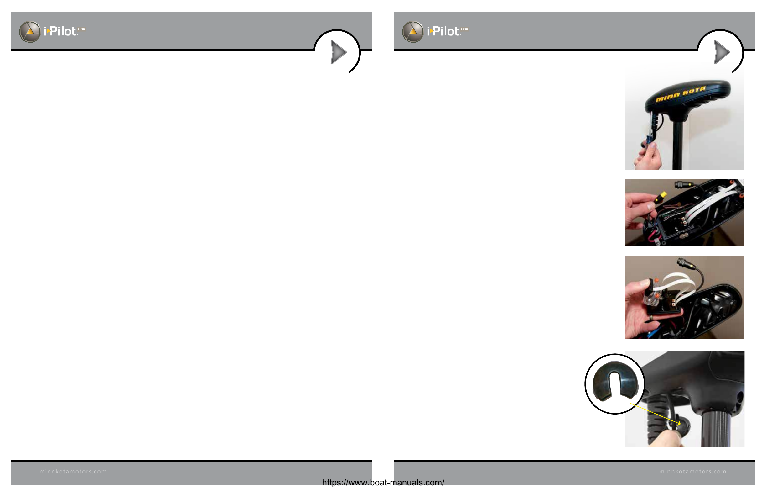
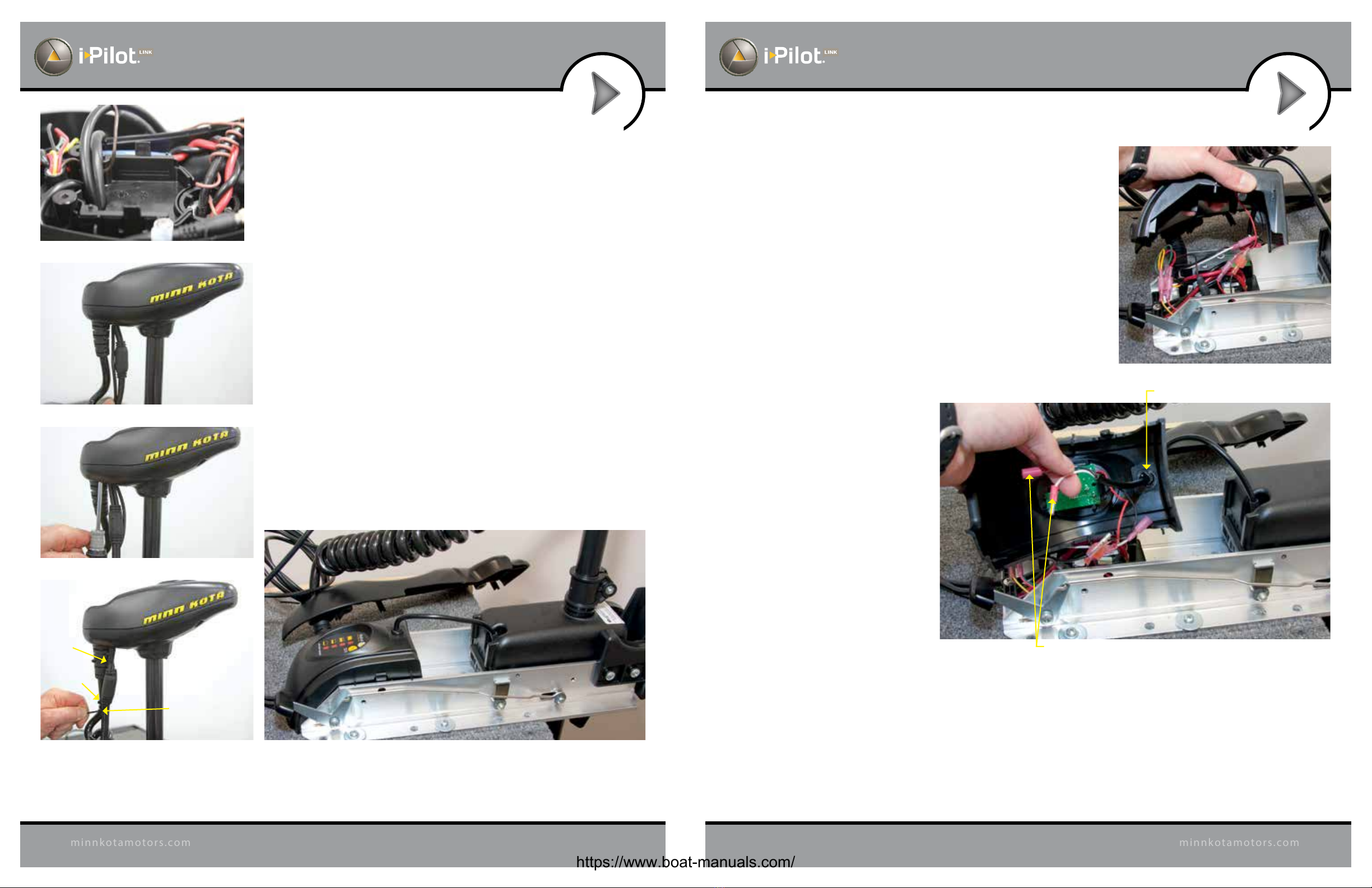
1. Disconnect all power to the trolling motor.
2. Remove control box cover screws and cover using Phillips
screwdriver. (Figure 1)
3. If the trolling motor has the AutoPilot feature, unplug the
AutoPilot control board and remove it from the control box.
(Figures 2 and 3)
4. Remove grommet by pulling back on coil cord strain relief and
pushing down on grommet. (Figure 4)
INSTALLATION OF IPILOT LINK CONTROLLER
Preparing for Installation
Tools you will need during installation
Terrova and Riptide ST
-Phillips screwdriver
PowerDrive V2
-Phillips screwdriver
-Needle-nose pliers
-Utility knife
-Heat gun or other heat source for installing heat shrink
Riptide SP
-Phillips screwdriver
-Needle-nose pliers
-Utility knife
-Heat gun or other heat source for installing heat shrink
To help with future service work or ordering replacement parts, please refer to the information box in the Notes
section located on the back pages of this manual.
Before installing i-Pilot Link on your motor, make sure the trolling motor is properly installed on your boat. Find a
clean and dry location for performing the installation.
Most importantly, disconnect all power to the trolling motor before installation. Not only will this protect you but
also the sensitive electronics you are about to install.
Read through the entire installation process before performing the installation.
If you need help or need further instruction on installing i-Pilot Link, please call Minn Kota technical service
at 1-800-227-6433 to talk to a customer service representative.
Humminbird Fishnder
DependingonyourHumminbirdmodelandsystemconguration,youmayneedtopurchaseadditional cables,as
shown below. Visit our Web site at humminbird.com or call the Customer Resource Center at 1-800-633-1468.
• 700 Series with Ethernet: To connect the Ethernet cable to the Fishnder, you will need to purchase the
Ethernet Adapter Cable (AS EC QDE).
• Extension Cables are available for the Ethernet Cable if you need to extend the connection longer than the
30 feet provided. See humminbird.com for details.
FIGURE 4
Grommet
https://www.boat-manuals.com/
10 11
minnkotamotors.com
minnkotamotors.com
INSTALLATION INSTALLATION
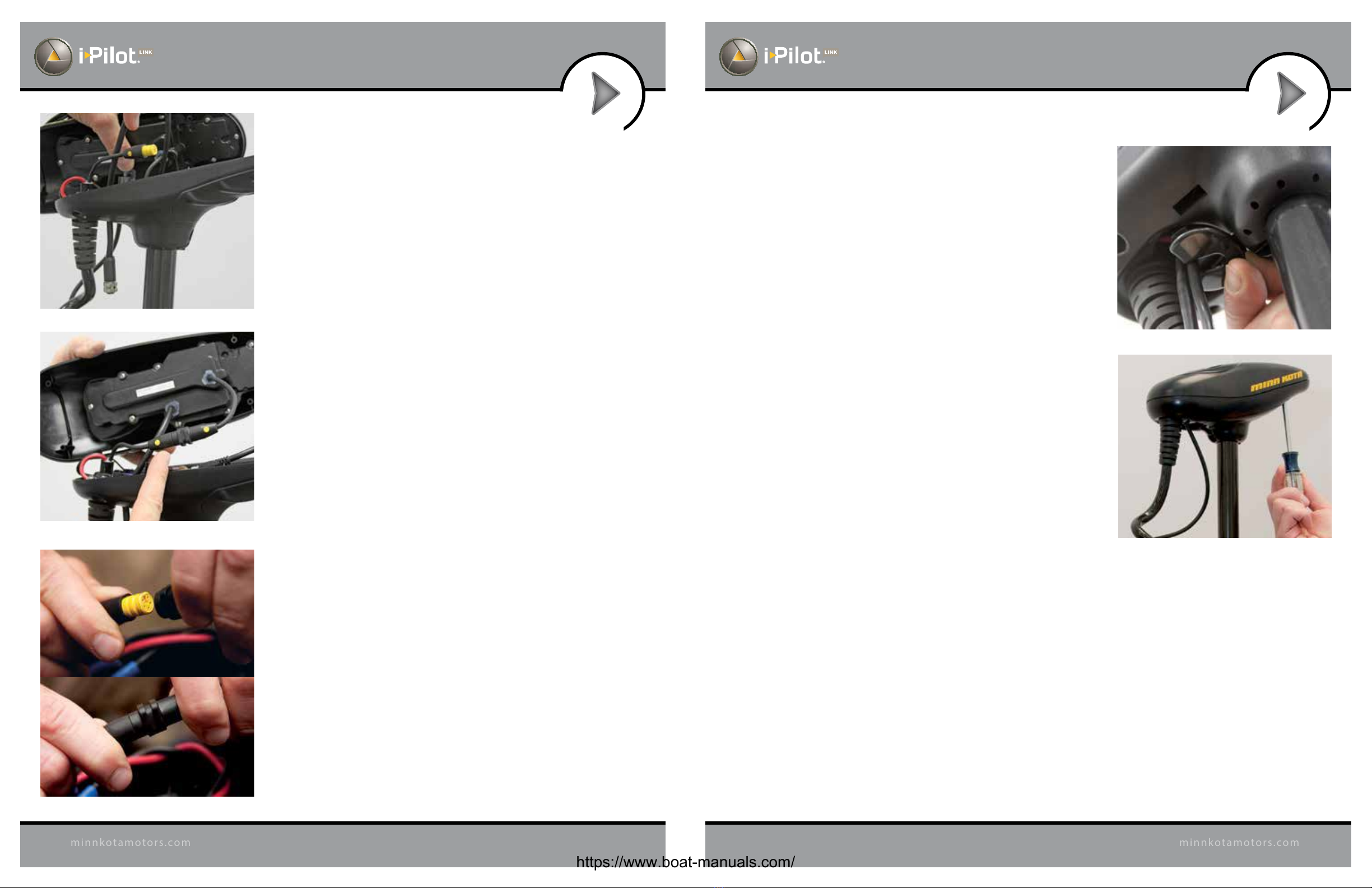
5. Route the Ethernet cable through the grommet hole and through
the center of the coil cord. (Figure 5)
6. Plug the i-Pilot Link controller connector into the accessory
connector as shown. (Figure 6) Be careful to orient connector
properly prior to pushing together.The plug will click twice when
pushing it together and the yellow end will be fully covered when
installed properly.
• Make sure connector is aligned properly. (Figure 7)
• Ensure connector is fully seated as shown. (Figure 7)
FIGURE 7
FIGURE 6
FIGURE 5
FIGURE 8
FIGURE 9
7. Installnewgrommetsuppliedwithi-PilotLinkbysnappingitintothe
hole located in front of the coil cord strain relief. (Figure 8)
8. Place the i-Pilot Link controller where the control box cover was
installed and secure with supplied #8 screws. Do not over tighten
screws. (Figure 9)
9. i-Pilot Link is now installed on the motor. Skip ahead to page 22 to
verify the installation.
https://www.boat-manuals.com/
12 13
minnkotamotors.com
minnkotamotors.com
INSTALLATION INSTALLATION
FIGURE 10
FIGURE 11
FIGURE 12
FIGURE 13
Grommet
FIGURE 15
FIGURE 14
i-Pilot Link Installation on PowerDrive V2
and Riptide SP
*Note: Once i-Pilot Link is installed in a PowerDrive V2 or
Riptide SP motor, the foot pedal cannot be used again unless
i-Pilot Link is fully uninstalled.
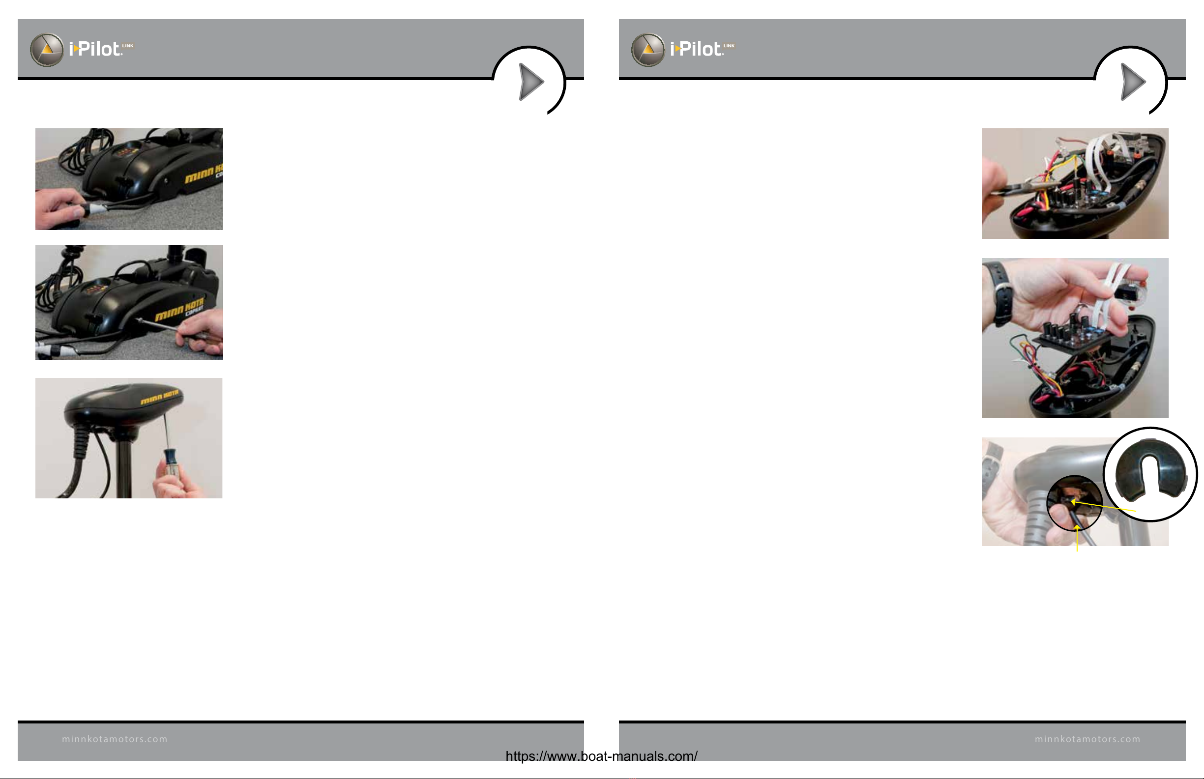
1. Disconnect all power to the trolling motor
2. If a CoPilot is installed, it must be removed as follows:
a. Disconnect motor connector and foot pedal connector from
CoPilot. (Figure 10)
b. Remove the CoPilot receiver from the motor by removing
both mounting screws. Do not replace these screws as the
side plates will be removed in step 13 of this installation.
(Figure 11)
3. Remove the control box cover screws and cover using Phillips
screwdriver. (Figure 12)
4. If the trolling motor has AutoPilot, it must be removed
as follows:
a. Disconnect all six AutoPilot connectors from AutoPilot
controller, using a needle-nose pliers and a utility knife
to remove any heat shrink insulation that may exist.
(Figure 13)
b. Remove the AutoPilot controller from the head of the
trolling motor (Figure 14). This is done by pushing out
thelockingtabsthenliftingthecircuitboardout. Finally,
lift out the compass.
5. Remove grommet by pulling back on coil cord strain relief
andpushingdownongrommetuntilitpopsout.(Figure15)
Sonar Cable (Universal Sonar Motors Only)
https://www.boat-manuals.com/
14 15
minnkotamotors.com
minnkotamotors.com
INSTALLATION INSTALLATION
FIGURE 18 Insert AutoPilot wires into terminal holders.
FIGURE 17
FIGURE 19
FIGURE 20 Insulate and seal six AutoPilot wires on Riptide
SP motors with supplied heat shrink.
Pinch ends of heat
shrink shut using
needle-nose pliers.
FIGURE 21 Place insulated AutoPilot wires in the
bottom center of the control box as shown.
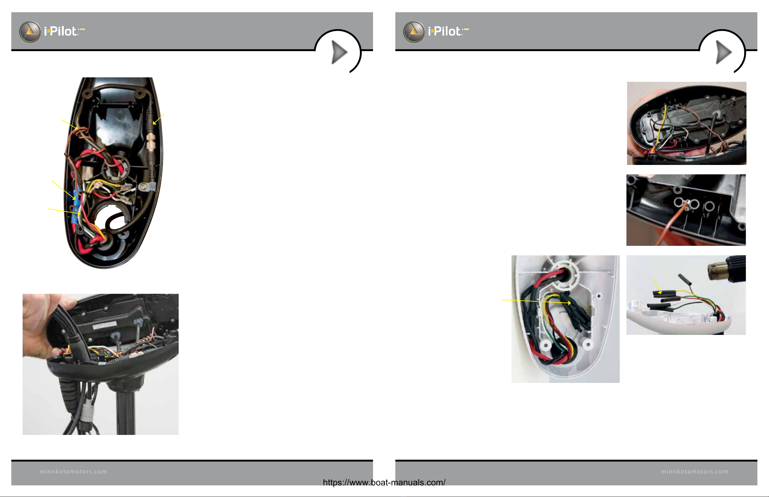
FIGURE 16
Sonar
Ground
Wire
Power Wires
AutoPilot Wires
(AutoPilot Motors Only)
Sonar
Cable
6. Review the cables in the head of the trolling motor
a. If a sonar cable is present, it must be routed around
the outer perimeter of the control box. The sonar
ground wire should also be routed as shown.
(Figure 16)
b. The motor power wires must be routed as shown.
(Figure 16)
7. Route the i-Pilot Link controller cable through the
grommet hole and through the center of the coil
cord (Figure 17).
8. If AutoPilot was removed, insulate the loose AutoPilot
connectors as follows:
a. For Powerdrive V2 Motors: Using a needle-nose pliers
pushallsix AutoPilotconnectors thatweredisconnected in
step4ontoterminalholderslocatedontheundersideofthe
i-Pilot Link Controller. (Figure 18)
IMPORTANT: Pull on each wire to make sure it is
secured properly. Loose wires can cause damage to
i-Pilot Link Controller and the entire motor.
AutoPilot connectors must be placed onto holders exactly
as shown. (Figure 19)
b. For Riptide SP motors: Apply heat shrink insulation
supplied in bag assembly to the ends of all six loose
AutoPilot connectors as shown (Figure 20). Use a zip tie
to bundle connectors together. Trim the zip tie and place
connectorbundleinthemiddleofthecontrolboxasshown.
(Figure 21)
https://www.boat-manuals.com/
16 17
minnkotamotors.com
minnkotamotors.com
INSTALLATION INSTALLATION
FIGURE 22
FIGURE 26FIGURE 25
Zip Tie
Location 1
Zip Tie
Location 2
Zip Tie
Location 3
FIGURE 24
FIGURE 23
Disconnect both wires by removing heat shrink and pulling them apart.
Entranceofsteeringcablethroughcenterhousing
FIGURE 27
FIGURE 28
9. Installnewgrommetsuppliedwithi-PilotLinkbysnappingitinto
the hole located in front of the coil cord strain relief.The i-Pilot
Linkcontrollercable must beplacedin the pass-through slot of
the grommet. (Figure 22)
10. Place the i-Pilot Link controller where the control box cover
was installed. Pull any extra controller cable out of the control
box by gently pulling on the cable. (Figure 23)
11. Secure cover with supplied #8 screws. Do not over tighten
screws. (Figure 24)
12. Secure the i-Pilot Link controller cable to the motor coil cord
in all three locations shown using zip ties provided. (Figure 25)
Trimzip ties using utility knife. Failureto securecablewillresult
in possible damage to the cabling during operation.
13. Remove the left and right side plates of trolling motor by
loosening all four side plate screws using a Phillips screwdriver
(Figure 26)
14. Removecenterhousingbypushinginonbothsidesandliftingup
at the same time. This will expose the main control board and
wiring. (Figure 27)
15. The steering motor cable passes through the top of the center
housing removed in step 14. This cable contains a black and
white wire. Disconnect these two wires by pulling each
connector apart. (Figure 28) Riptide SP motors will have these
connections covered with heat shrink which must be removed
with a utility knife.
https://www.boat-manuals.com/

18 19
minnkotamotors.com
minnkotamotors.com
INSTALLATION INSTALLATION
16. Loosen the cable strain relief that is secured to the base
of the motor and install the i-Pilot Link controller steering
cable into the open strain relief slot. (Figure 29)
17. Tighten the cable strain relief as shown. The i-Pilot Link
controller steering cable should slide freely through the
strain relief when installed properly. (Figures 30 and 31)
FIGURE 29
Foot Pedal Cable
Motor Power Cable
i-Pilot Link Controller
Steering Cable
FIGURE 31FIGURE 30
Reinstall strain
relief screw.
FIGURE 32
Slide heat shrink
over steering
motor wires.
18. Slide four pieces of heat shrink insulation over each side of the
wires that were disconnected in step 15. (Figure 32)
https://www.boat-manuals.com/
20 21
minnkotamotors.com
minnkotamotors.com
INSTALLATION INSTALLATION
FIGURE 33
Connect
steering wires:
white to white
black to black
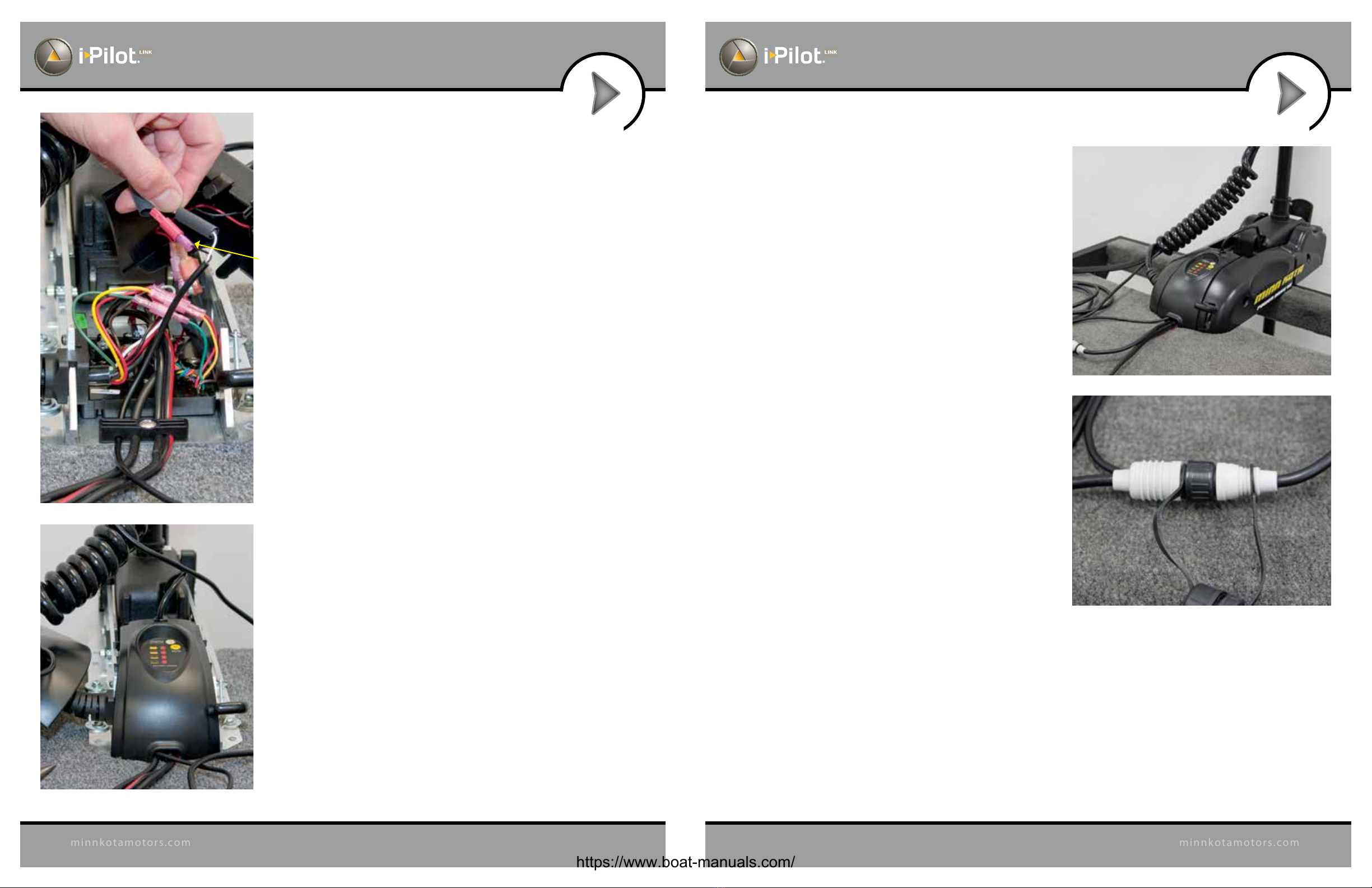
19. Connect the black and white wires from the i-Pilot Link
controller cable to the black and white steering motor
wires,makingsureblackisconnectedtoblackandwhite
is connected to white. (Figure 33)
20. Completetheinstallationbypositioningtheheatshrink
overtheconnectionsandshrinkdown,usingaheatgun
or other heat source, being careful not to overheat any
wire or parts.
Seal connections with heat shrink.
IMPORTANT: DO NOT OVERHEAT WIRES OR
SURROUNDING PARTS WHEN INSTALLING
HEAT SHRINK!
21. Reinstallcenterhousingovercontrolboardbypushingit
down until the side ngers lock into place. The new
i-Pilot Link Controller steering cable should be exiting
the cable exit hole at the center and bottom of the
center housing. (Figure 34)
FIGURE 34
FIGURE 35
FIGURE 36
22. Reinstall both side plates using Phillips screwdriver. If
a Co-Pilot was uninstalled, use new ¼-20 x 5⁄8" Phillips
screws provided. (Figure 35)
23. If a foot pedal is connected to the trolling motor, it
must be disconnected. Once i-Pilot Link has been
installedthefootpedalcannotbeusedunlessi-PilotLink
is completely uninstalled.
24. Connect i-Pilot Link controller cable to the foot pedal
connector, making sure the connector nut is tight
(Figure 36)
IMPORTANT: DO NOT place dielectric grease or any type
of lubricant in the connector.
25. i-Pilot Link is now installed on the motor. Skip ahead to
the next section to verify the installation.
https://www.boat-manuals.com/
22 23
minnkotamotors.com
minnkotamotors.com
INSTALLATION INSTALLATION
VERIFYING INSTALLATION OF IPILOT LINK
CONTROLLER AND REMOTE
It is important to verify your i-Pilot Link installation prior to going on the water. If this cannot be done, it is highly
recommended that system verication be done in an open area on a calm day with a fully operational outboard motor
for a backup means of powering your boat.
To verify that i-Pilot Link is working properly before going on the water, follow the steps below.
1. Trolling motor should be correctly installed and mounted to the bow of a boat.
2. The boat and trolling motor must be located outside and have a direct view of the sky to obtain
GPS satellite signals.
3. Verify that all obstructions are away from the prop in all directions in both the stowed and deployed positions.
4. Connect power to the trolling motor.
5. Deploy the motor so the motor shaft is completely vertical.
6. The i-Pilot Link controller will emit four short beeps on startup.
7. Turn on the remote by pressing the OK key and verify the LCD comes on.
8. When i-Pilot Link is powered up, it starts to gather satellite information about its location. A minimum satellite
signallevelmustbeachievedbeforealli-PilotLinkfunctionalityisavailable.Thisminimumlevelisonebaronthe
GPS signal icon. With no bars showing, only manual functions will be available.
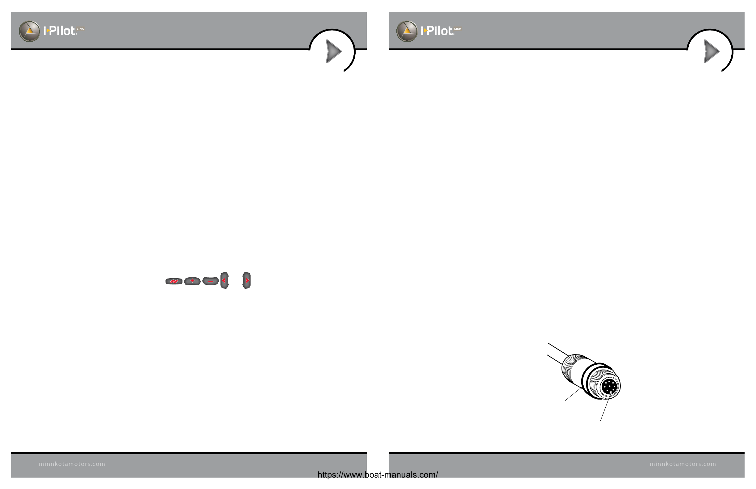
9. Verify all manual functions by pressing and .
10. If you experience any problems with any of the steps above, or cannot obtain a GPS satellite signal, refer to the
troubleshooting section.
CONNECT THE IPILOT LINK TO THE
HUMMINBIRD FISHFINDER
The i-Pilot Link can be connected directly to the Humminbird Fishnder or to the Humminbird Ethernet Switch
(optional). If you purchase the Ethernet Switch, install it using the instructions in the Ethernet Accessory Guide.
WARNING! The power source must be turned o before you proceed with this installation.
NOTE: The Ethernet extension cable is optional for your installation. If you need to purchase additional
extension cables, visit our Web site at humminbird.com or call the Humminbird Customer Resource Center
at 1-800-633-1468.
1. Locate the Ethernet cable on the i-Pilot Link.
2. If you are using the Ethernet extension cable for your installation, connect it to the Ethernet cable on
thei-PilotLink.Theconnectorsarekeyedtopreventreversedinstallation,sobe carefulnotto forcethe con-
nectors together. Hand-tighten the screw nut.
If you do not need the Ethernet extension cable for your installation, proceed to step 3.
3. Route the cable to the Humminbird Fishnder (or the optional Ethernet Switch).
NOTE: The cable should be routed through an established routing system on the boat, in an area with minimal
interference.Inspecttheselectedroutecarefullytoensurethattherearenosharpedges,obstacles,orobstructions
that may damage the cables.
4. 700 Series: Connect the Ethernet Cable to the Ethernet Adapter Cable (AS EC QDE). Insert the
connectorintothe Ethernet porton the cablecollector. See yourHumminbirdinstallationguidefordetails
about installing the quick disconnect mount.
800/900/1100 Series: Insert the other end of the Ethernet Cable into the Ethernet port on the Fishnder.
Hand-tighten the screw nut.
Hand-Tightening the Screw Nut
The connectors
are keyed to
prevent reversed
installation.
Screw Nut
https://www.boat-manuals.com/
24 25
minnkotamotors.com
minnkotamotors.com
INSTALLATION INSTALLATION
VERIFYING INSTALLATION ON THE
HUMMINBIRD FISHFINDER
All equipment should be connected and powered before you turn on the Fishnder. When the i-Pilot Link is
detected,
i-PilotLinkConnected
will displaybriey onthescreen.Youcanalsoconrmtheinstallationconnections
using the following instructions.
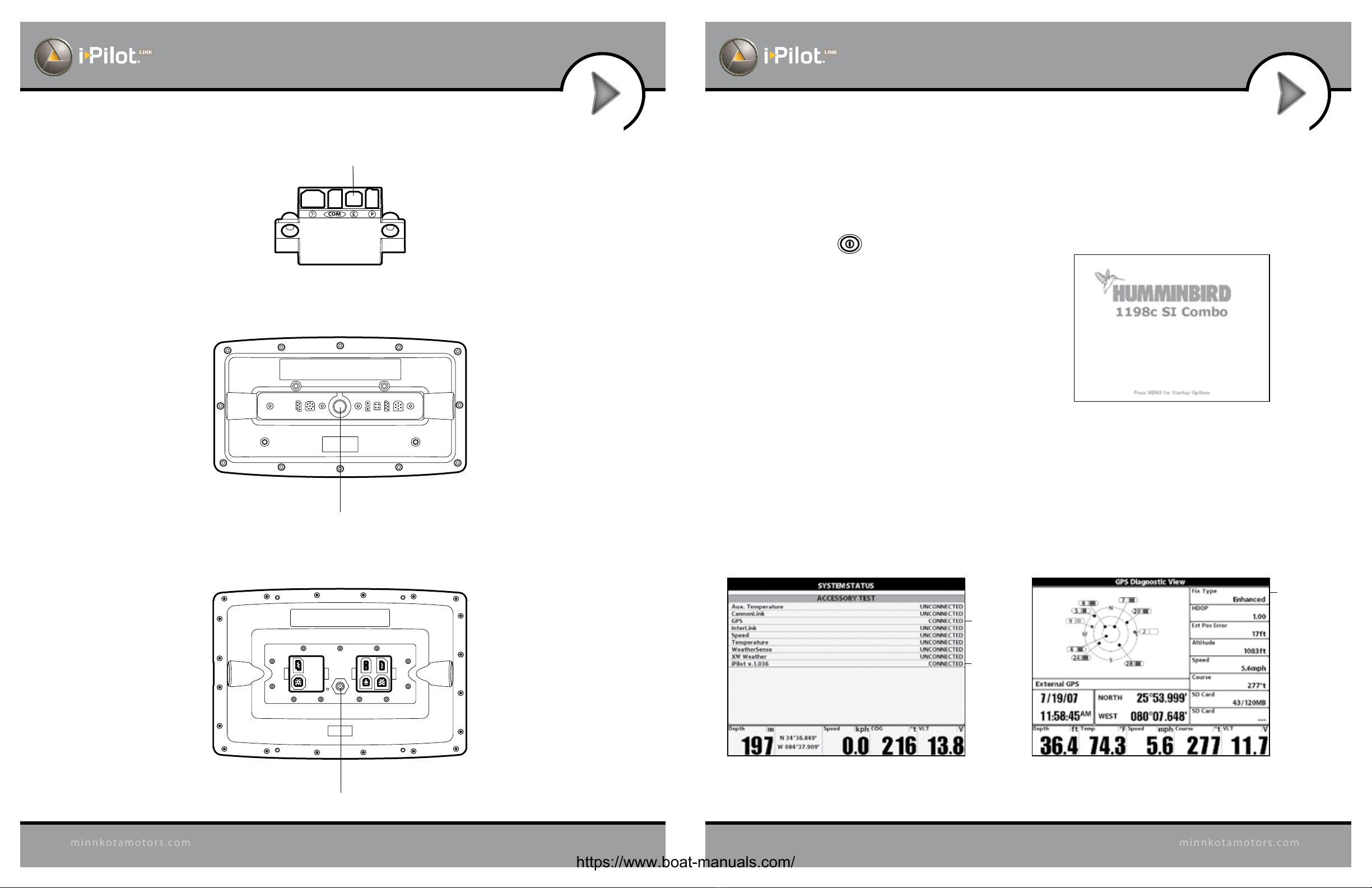
1. Press the POWER/LIGHT key on the Fishnder.
2. When the Title screen is displayed, press the MENU key
to open the Start-Up Options Menu.
3. Use the 4-WAY Cursor Control key to select Normal,
and press the RIGHT Cursor key.
4. Press and hold the VIEW key. Select System > Accessory
Test. Conrm that i-Pilot Link is listed as connected. It
may take a minute for the equipment to be detected.
5. Press and hold the VIEW key. Select System > GPS
Diagnostic View. Conrm that External GPS is displayed
and the Fix Type indicates Enhanced or 3D.
NOTE: A GPS Receiver is required to enable the navigation features on the Fishnder. The Fishnder uses the
data from the GPS Receiver attached directly to it or selected from the Ethernet network.
NOTE: If the GPS Diagnostic View or Accessory Test is not displayed in the View Rotation, press the MENU key
twice to open the Main Menu. Select the Views tab > GPS Diagnostic View or Accessory Test. Change the
setting for each view to Visible.
Conrming the GPS Fix Type
Fix Type
shouldbe
3D or
Enhanced
Conrming that i-Pilot Link is Detected
i-Pilot Link
listed as
connected
GPS listed as
connected
Title Screen
700 Series Cable Collector with Ethernet
Ethernet
800/900 Series (rear view)
Ethernet Port
1100 Series (rear view)
Ethernet Port
https://www.boat-manuals.com/

GETTING STARTED
REMOTE OPERATIONS
GETTING STARTED
REMOTE OPERATIONS
26 27
minnkotamotors.com
minnkotamotors.com
KNOWING YOUR REMOTE
Remote Layout
See diagram to the right.
Power
To turn the remote
on, press the OK key.
To turn the remote o, press and
hold the OK key or select
Home > Settings > O – OK
Construction
The remote is waterproof and
oats in water.
Range
The range of the remote will be
greatly reduced if it is used near
or mounted to any metal object
including aluminum or steel.
It is also recommended that the
front end of the remote not be
obstructed during use.
MENU CONTROL KEYS
Left Softkey & Right Softkey
These keys change function based on mode
of operation and which screen is presently
displayed. The Softkey Labels at the bottom
of the LCD indicate their current function.
Menu Up & Menu Down
Used to navigate the menus.
Home
Pressing this key will always bring up the
Home Screen.
OK
Press to accept menu selections.
Remote power:
• Pressandreleasetoturntheremoteon.
• Pressandholdfor3secondstoturnthe
remote off.
MANUAL CONTROL KEYS
Speed Up
Speed Down
Prop On/Off
Auto Pilot
Press to enable AutoPilot or
Advanced AutoPilot.
The default mode is selected through the
Controls Menu on the remote.
Cruise Control
Press to bring up the Cruise Control
Access screen. Target speed is adjusted
using the + and – keys and accepted using
the OK key.
GOTO
Opens the list of iTracks, Spot-Locks and
Waypoints that are within navigable range.
Also used to switch from the Home Screen
to the Active Screen during i-Pilot navigation.
Spot-Lock
Press to enable Spot-Lock.
Press and hold to mark a Waypoint
on the Humminbird (Spot-Lock will
not engage).
NAVIGATION KEYS
HEADER
DASHBOARD
INFO BOXES
CONTENT
AREA
SOFTKEY
LABELS
KEYPAD
KEYPAD
DASHBOARD
HEADER
QUICK REFERENCE
GUIDE
Steer Left
Steer Right
State-of-Charge indicator
for the remote battery.
GPS Signal Strength
Flashing indicates no GPS fix.
Humminbird Connection
Highlights when the i-Pilot controller is in
communications with the Humminbird.
When there are no communications,
the arrows turn gray.
Time and Date
This data is provided by the GPS.
12:1
3 PM OCT 18
12:13 PM OCT
18
Recording an iTrack
When the red dot is shown, it
indicates that Link is currently
recording an iTrack.
Legacy
AutoPilot
Advanced
AutoPilot
Cruise Control
Target Speed
Navigation Mode
Motor Speed
Cruise Control
When the icon is shown,
the Cruise Control feature
is enabled.
Spot-Lock
Navigating
to Start
Navigating
to End
Navigating
to Waypoint
Following a
Contour
Navigating
a Route
Spot-Lock Paused
Prop Status
The states of the prop icon are:
• Propiconisnoton=propisdisabled.
• Onsteadybutnotrotating=propis
enabled but the prop speed is zero.
• Rotating=propisenabledandspeed
is greater than zero.
• Blinking=propisdisabledbutLinkis
in a mode of navigation and the user is
being reminded to enable the prop.
GPS Speed
Charging Battery
Full Battery
Low Battery
2377155 Revision B
https://www.boat-manuals.com/
GETTING STARTED
REMOTE OPERATIONS
GETTING STARTED
REMOTE OPERATIONS
28 29
minnkotamotors.com
minnkotamotors.com
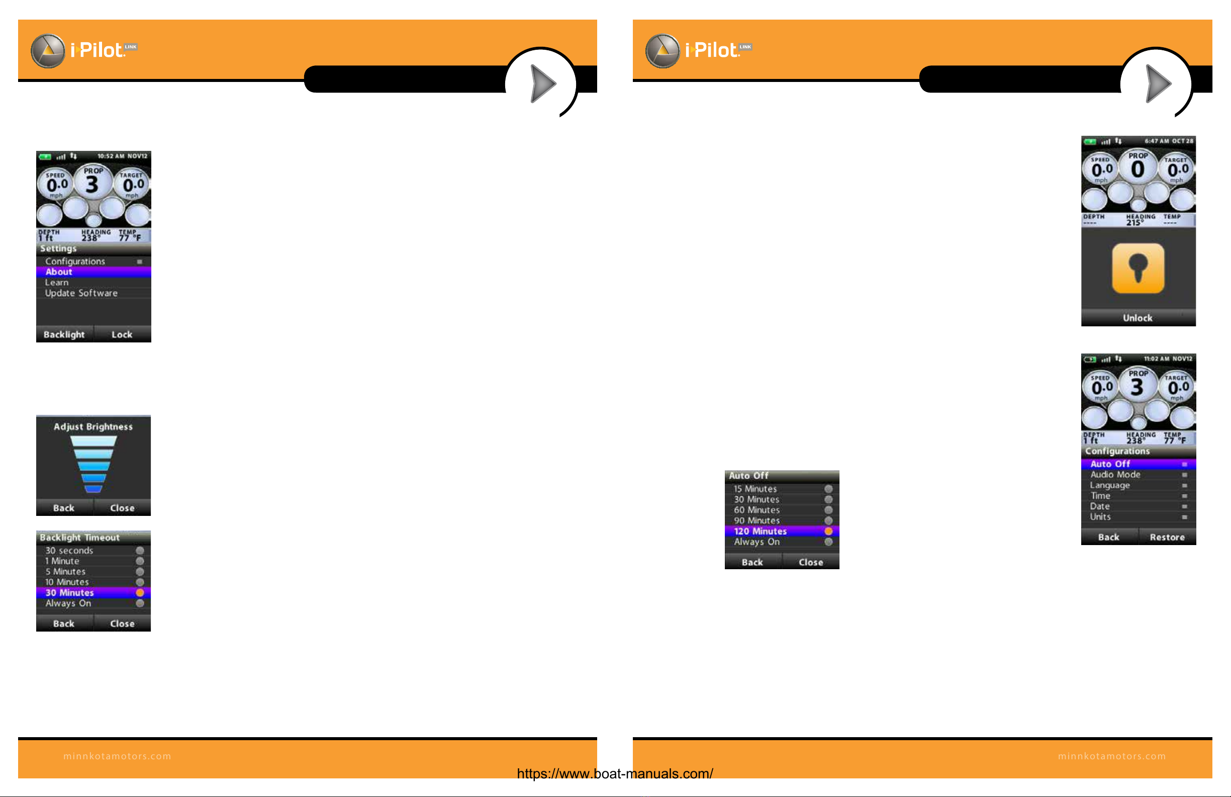
Backlight Settings:
Settings Menu > Backlight Softkey
Backlight Settings > Brightness
This screen allows the user to manually control
the brightness of the backlight. Use the up/down
arrow keys to adjust. Select the Back or Close
Softkey to save the setting and exit.
Backlight Settings > Timeout
Theselections onthisscreencontrolhowlongthe
backlight will stay on after the last key press. Use
the up/down arrow keys to select a new value and
press the OK key to accept.
Keypad Lock:
To lock the keypad: From the Settings menu, press and hold the Lock Softkey.
To Unlock the keypad: Press and hold either Unlock Softkey.
Settings:
Settings > Congurations
Congurations menu
Enterthismenu byselecting Home>Settings Softkey >Congurations>OK
Congurations > Restore Softkey
This selection allows the user to reset the congurations on the remote to
factory defaults.
Congurations > Auto O
The selections on this menu control how long
after the last key press the remote will
automatically shut o. Use the up/down arrow
keys to select a new value and press the OK key
to accept. Select the Back or Close Softkey to
save the setting and exit.
Congurations > Audio Mode
a. The selections on this menu control how long after the last key press the
remote will automatically shut o. Use the up/down arrow keys to select
a new value and press the OK key to accept. Select the Back or Close
softkey to save the setting and exit.
b. Refer to the Audio Modes section of the manual for further details.
Settings menu
SETTINGS MENU
To enter the Settings Menu, select Home > Settings Softkey
Keypad Lock
Settings>Congurations
https://www.boat-manuals.com/

GETTING STARTED
REMOTE OPERATIONS
GETTING STARTED
REMOTE OPERATIONS
30 31
minnkotamotors.com
minnkotamotors.com
Congurations > Language
Fromthismenu,theuserhastheoptionofchangingthelanguageofthetext
that appears on the remote screen. Use the up/down arrow keys to select a
new language and press the OK key to accept the setting and exit the menu.
Or, select the Back or Close Softkey to exit without making changes.
Congurations > Time
From this menu, the user congures the following:
a. 12-hour/24-hour: This controls the format that the time appears in on
the screen header. Use the up/down arrow keys to select the desired
format a new value and press the OK key to accept. Select the Back or
Close Softkey to save the setting and exit.
b. Time Zone: Choosing this
selection will bring up a list
of time zones.
c. DaylightSavings: ThischeckboxisusedtoconguretheLink remoteand
controller to account for Daylight SavingsTime. Highlight this checkbox
and use the OK key to enable/disable the feature and select the Back or
Close Softkey to exit the screen.
Congurations > Date
From this menu, the user congures the format that the date appears on GOTO screen
on remote. Use the up/down arrow keys to select a new value and press the OK key
to accept. Select the Back or Close Softkey to save the setting and exit.
Congurations > Units
From this menu, the user congures the following:
a. Depth: Choosing this selection will bring up
a list of units to use when displaying depth.
Use the up/down arrow keys to select a new value
and press the OK key to accept. Select the Back or
Close Softkey to save the setting and exit.
b. Distance: Choosing this selection will bring up
a list of units to use when displaying distance.
Use the up/down arrow keys to select a new
value and press the OK key to accept. Select the
Back or Close Softkey to save the setting and exit.
c. Speed: Choosing this selection will bring up
a list of units to use when displaying speed.
Use the up/down arrow keys to select a new value
and press the OK key to accept. Select the Back or
Close Softkey to save the setting and exit.
d. Temperature: Choosing this selection will bring up a
list of units to use when displaying temperature.
Use the up/down arrow keys to select a new value
and press the OK key to accept. Select the Back or
Close Softkey to save the setting and exit.
Settings > About
Displays the current revisions of software for the remote and the controller
Settings > Learn
Used during the process of learning the remote to a controller (see details on page 33)
Settings > Update Software
Used to check for and initiate software updates for the remote. See details in the Software Update section.
Congurations > Units
Congurations > Date
Congurations > Language
Congurations > Time
ft or sm = feet or statute miles
m or km = meters or kilometers
ft or nm = feet or nautical miles
m or nm = meters or nautical miles
https://www.boat-manuals.com/

GETTING STARTED
REMOTE OPERATIONS
GETTING STARTED
REMOTE OPERATIONS
32 33
minnkotamotors.com
minnkotamotors.com
Controls > Resume
When navigation is paused (Spot-Locked), selecting Resume will restart the original
navigation mode. Note that this selection is only available when navigation is
currently paused.
Controls > Reverse
While navigating an iTrack or contour line, selecting Reverse will change the
direction of travel. Note that this selection is only available while navigating these
types of features.
Controls > Record
Select Record tobeginrecordinganiTrack.Thisselection is also used toreturnto the
Record Active screen if a recording is in process and the user has brought up a dier-
ent screen.
Controls > Arrival Mode
Theselectionsonthismenuareusedtotelli-PilotLinkwhattodowhenadestination
is reached during certain types of navigation. Use the up/down arrow keys to select
the setting and press the OK key to accept. Select the Back or Close softkey to save
the setting and exit.
a. This same conguration is accessible through the Humminbird.
Controls > Autopilot Mode
From this menu the user congures which version of AutoPilot to use when
AutoPilot is engaged. Use the up/down arrow keys to select the setting and press
the OK key to accept. Select the Back or Close Softkey to save the setting and exit.
a. This same conguration is accessible through the Humminbird.
Controls > Sort Order
Theselectionsonthismenucontroltheorderinwhichnavigationalpointsappearon
the GOTO screen. Use the up/down arrow keys to select a new value and press the
OK key to accept. Select the Back or Close softkey to save the setting and exit.
Controls Menu
Controls > Arrival Mode
Controls > Autopilot Mode
CONTROLS MENU
To enter the Controls Menu, select Home > Controls Softkey
i-Pilot Link
Speaker
Remote Learn
Button
KNOWING YOUR IPILOT LINK CONTROLLER
Construction
The i-Pilot Link controller contains a very sensitive digital compass and is where all GPS
satellite and i-Pilot Link remote signals are received. It is very important that the controller
has a clear view of the sky in all directions and has a clear line of sight to the remote for
optimumperformance.Allelectronicswithinthecontrollerenclosurearecompletelysealed.
Remote Learning
The i-Pilot Link remote is prelearned to the controller from the factory. The top of
the controller has a single learn button to allow additional remotes to be added
to the system. To learn additional remotes:
1. Power up the trolling motor.
2. Push and hold the learn button down. A steady audio tone will
be heard while holding this button.
3. While holding the learn button on the controller, from the remote home screen select:
Settings > Learn and press the OK key
4. If the learn process was successful, the controller will respond with four beeps. In
addition, the Dashboard section of the remote will begin to display motor status
information such as prop speed.
A remote can only be learned to one controller at a time. A controller can have up to
4 remotes learned to it and actively communicating with it.
Controls > Sort Order
The i-Pilot Link remote contains a rechargeable battery. To charge the
battery, plug the USB end into the included AC adapter and plug the
other (two pronged) end into the charging port of the remote. The
Charging Indicator will illuminate whenever an energized charging
cable is connected.
The user also has the option of plugging the USB end of the charging
cable into any USB type power source. The remote can be recharged
while the remote is on or o.
NOTE: The USB end of the charging cable is not intended for
prolonged exposure to saltwater environments.
REMOTE BATTERY
Charging
Port
Charging
Indicator
https://www.boat-manuals.com/

34 35
minnkotamotors.com
minnkotamotors.com
GETTING STARTED
CONTROLLER OPERATIONS
Audio Modes
Thei-Pilot Link Controlleralso containsaninternalspeaker which can be programmedtowork in two dierent
audio modes. The speaker is programmed to operate in audio mode one from the factory. To select the
dierent audio modes, from the Home screen go to: Settings > Congurations > Audio Mode. For an
explanation of each audio mode and their sounds see the table below.
WHAT CONDITION CAUSES IT
AUDIO
MODE
AUDIO
PATTERN
Start up Modes 1 and 2 4 short beeps
Manual prop on Mode 2 Single beep
Manual prop o Mode 2 Double beep
Speed + Mode 2 Single beep
Speed - Mode 2 Single beep
Enabling any of these functions: GoTo iTrack, GoTo
Waypoint, Spot-Lock, AutoPilot, Cruise Control
Mode 2 Single beep
When GPS signal strength goes to no bars while in a
GPS-based mode
Modes 1 and 2 Error
AttemptingtoenableaGPS-basedmodewhennosignal
strength bars are shown
Modes 1 and 2 Error
MOM button on the footpedal is pressed and a remote
button press attempts to override it
Mode 2 Error
End of an iTrack is reached and the termination option
is set to OFF
Mode 2 4 longer beeps
Learn button is pressed Modes 1 and 2 Steady tone
Learn successfully completed Modes 1 and 2 4 longer beeps
Power
The i-Pilot Link controller will turn on whenever the trolling motor has power. For Terrova and Riptide ST
motors this is when the green system ready light is on. For PowerDrive V2 and Riptide SP motors this is
whenever the motor is connected to power.
* For this reason it is very important to disconnect a PowerDrive V2 or Riptide SP motor from power when not in
use or battery drain will occur.
Accuracy
Theaccuracyandresponsivenesswithwhichi-PilotLinkcontrolsyourboatishighlydependentuponmanyvariables.
Just a few of these variables and their general eects on responsiveness and accuracy are given below so that the
behavior of the system can be understood.
System Startup
Once you have veried i-Pilot Link’s installation it’s time to start using it on the water. Follow these simple steps
each time you power up your trolling motor for successful operation:
1. Connect trolling motor to power.
2. Deploy trolling motor into water.
3 Turn the remote on by pressing the OK key. Verify the Dashboard section of the screen shows all motor
status information.
4. You are now able to use all manual functions: and .
5. After i-Pilot Link has obtained a minimum GPS signal strength of one bar, all remaining functions will
become available.
VARIABLE EFFECT
Ratio of motor thrust to boat weight Excessive thrust on a smaller boat can cause i-Pilot Link to overcorrect.
Notenough thruston alargeboatcan causei-PilotLinktorespondslowly.
Wind Excessive wind and/or current can reduce i-Pilot Link’s
positioning accuracy.
GPS signal strength The greater number of GPS signal bars the greater
the accuracy.
Trolling motor battery power level A fully charged battery will give the best performance.
GETTING STARTED
CONTROLLER OPERATIONS
https://www.boat-manuals.com/
36 37
minnkotamotors.com
minnkotamotors.com
GETTING STARTED
SOFTWARE UPDATES
5. Press and hold the Fishnder VIEW key. Select System > Accessory Test.
6. Conrm that i-Pilot Link is listed as connected. It may take a minute for the equipment to be detected.
Youwill referto this view throughout the update.Note the currentsoftwareversion number shownnext
to i-Pilot Link.
NOTE: If the Accessory Test View is not shown in the submenu, select the Main Menu > Views tab > Accessory
Test > Visible.
3. Update the Software
1. Install the SD card with the updated software les into the Fishnder card slot.
2. Fishnder Update: The Fishnder will recognize the new software. Follow the dialog box
instructions to conrm software installation.
i-Pilot Link Update: The software will be updated automatically. It may take up to two minutes for the
softwaretobedetectedonthenetwork,andtheFishnderwilldisplayon-screendialogboxestoindicate
that the update is in progress.
NOTE: You may notice that the i-Pilot Link will disconnect and then reconnect during the software update.
This is part of the update process.
3. When the i-Pilot Link software has been updated, the new software version number will be displayed on
the Fishnder Accessory Test View.
4. To nish updating the remote and controller, proceed to the next section.
4. Update the Remote
The new software for the remote is now loaded on the Link Controller. You must now go to the
remote and initiate the download of the remote software to the remote itself.
1. From the remote Home screen, select: Settings Softkey > Update Software > OK.
2. From this screen, select the Update option.
3. A message saying “Software Updating”will appear along with a progress bar. After that, another
message saying “Programming Flash” will appear along with a progress bar.
4. After the second progress bar nishes, the remote will automatically restart.
5. Update the Link Controller
1. Cycle power to the trolling motor to regain proper motor control.
36 37
minnkotamotors.com
minnkotamotors.com
GETTING STARTED
SOFTWARE UPDATES
SOFTWARE UPDATES
Set up an online account at humminbird.com so that you will receive the latest Humminbird news and software
updates for your Fishnder. The i-Pilot Link remote and controller software are also updated through the
Humminbird Fishnder.
WARNING! Humminbird is not responsible for the loss of data les (waypoints, routes, tracks, groups,
snapshots, recordings, etc.) that may occur due to direct or indirect damage to the unit’s hardware or software.
It is important to back up your Fishnder’s data les periodically. Data les should also be saved to your
PC before restoring the unit’s defaults or updating the software. See your Humminbird online account at
humminbird.com and the Waypoint Management Guide.
Required Equipment
Personal computer with Internet access, a formatted SD memory card, a USB Memory Card Reader (AS CR),
and an i-Pilot Link compatible Humminbird Fishnder.
NOTE: To purchase equipment, visit ourWeb site at humminbird.com or contact our Customer Resource Center
at 1-800-633-1468.
1. Download the Software
1. Install a formatted SD memory card into the card reader connected to your PC.
2. Register your Fishnder: Log on to humminbird.com. Click My Account. Set up a new account or log
into your current account and add the i-Pilot Link to your My Equipment tab.
3. Download:FromMyAccount\My Prole\MyEquipment,click thelename ofthelatest softwareupdate
(unit name [version #]) for your Fishnder.
• Read the instructions in the dialog box and click Download.
• Follow the on-screen instructions to save the software les directly to the SD Card.
4. Repeat step 3 to download the i-Pilot Link controller and remote software les.
NOTE: The timing of software updates may vary, so there might not be 3 les required for download every time
you visit your Humminbird online account.
2. Prepare the Equipment
1. Turn on the main power source.
2. Power on the trolling motor. If you have a Terrova or Riptide ST trolling motor, deploy it into the water.
3. Turn on the remote by pressing the OK key. Ensure the battery is well charged. If the battery charge is not
sucient, you will be prompted during the process to plug in the charger.
4. Turn on the Fishnder by pressing the POWER/LIGHT key, and follow the on-screen prompts to
start Normal mode.
https://www.boat-manuals.com/
GETTING STARTED
REMOTE OPERATIONS
GETTING STARTED
REMOTE OPERATIONS
38
minnkotamotors.com
SET THE ARRIVAL MODE
When you are navigating with the i-Pilot Link and reach the destination, set the Arrival Mode
menu option to tell the system what to do next. The setting will determine if you will control the
boat manually or transition to another type of i-Pilot Link navigation after the destination point is
reached in a waypoint, route, or iTrack.
NOTE: The Arrival Mode menu setting does not apply to Spot-Lock or Follow the Contour.
O returns the unit to manual mode after navigation is nished. You must be prepared to take
manual control of the boat.
Spot-Lock creates a Spot-Lock and engages a Spot-Lock after navigation is nished.
AutoPilot continues navigation towards the set AutoPilot heading.
From the Humminbird:
1. Main Menu: Press the MENU key twice.
2. Select the Accessories tab > i-Pilot > Arrival Mode.
3. Press the RIGHT or LEFT Cursor keys to select O, Spot-Lock, or AutoPilot.
(Default = O )
From the remote:
1. From the Home screen, select the Controls Softkey > Arrival Mode > OK.
2. Use the up/down arrow keys to select a new value and press the OK key to accept.
Select the Back or Close Softkey to save the setting and exit.
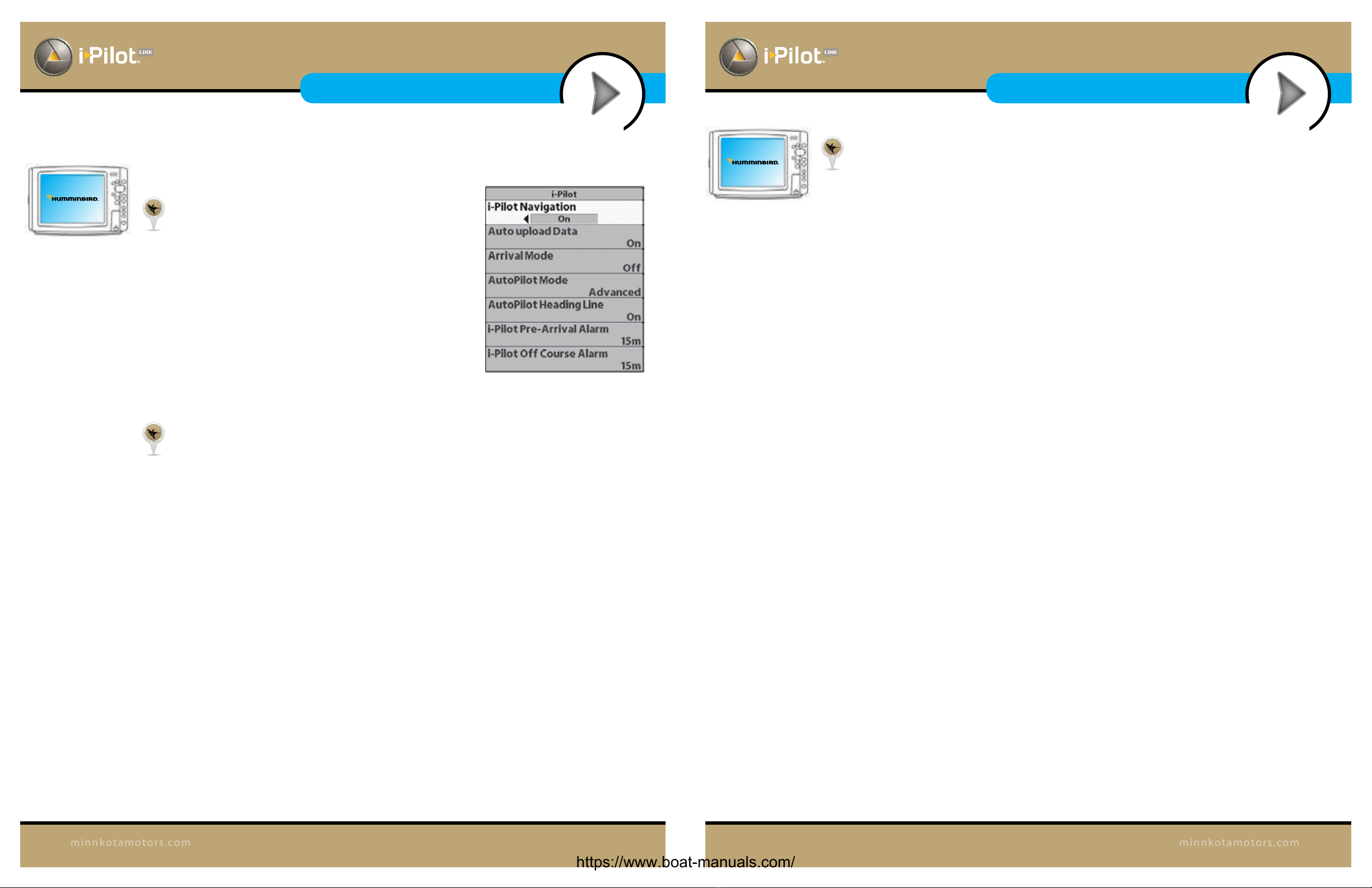
From the Humminbird:
ENABLE IPILOT LINK NAVIGATION
To start i-Pilot Link navigation from the Fishnder, the i-Pilot
Navigation menu option must be turned on. When i-Pilot
Navigation is turned on, the related i-Pilot Link menus will
be added to the menu system. If i-Pilot Navigation is turned
o, your Fishnder will operate with its traditional
Humminbird navigation features.
NOTE: When i-Pilot Navigation is turned on, navigation
from other connected autopilots will be cancelled.
1. Main Menu: Press the MENU key twice.
2. Select the Accessories tab > i-Pilot > i-Pilot Navigation > On or O. (Default = On)
UPLOAD DATA FROM THE IPILOT LINK
When Auto Upload Data is turned on, the Fishnder copies the i-Pilot Link’s saved iTracks and
Spot-Locks. In this case, the Fishnder and i-Pilot Link are synchronized, so if you delete a
Spot-Lock or iTrack on the Fishnder, it will be deleted on the i-Pilot Link. When Auto Upload
Data is o, deleting an item on the Fishnder will not aect the data stored on the i-Pilot Link and
vice versa.
1. Main Menu: Press the MENU key twice.
2. Select the Accessories tab > i-Pilot > Auto Upload Data > On or O. (Default = On)
NOTE: The maximum number of iTracks, Spot-Locks, waypoints, routes, and tracks may
vary due to the setup of your Waypoint Management directory. Groups and sub-groups also
use storage, and the storage limit is inuenced by the complexity of your Waypoint
Management directory. See Manage your i-Pilot Link Navigation Data for details.
IPILOT SETUP
39
minnkotamotors.com
I-PILOT SETUP
FISHFINDER OPERATIONS
I-PILOT SETUP
FISHFINDER OPERATIONS
https://www.boat-manuals.com/
Other manuals for i-Pilot Link
10
Table of contents
Other MINN KOTA Control System manuals


Popular Control System manuals by other brands


Fly Sky
Fly Sky FS-T4B instruction manual

Crestron Electronics
Crestron Electronics UC-B30-T quick start

Firecom
Firecom SCB-7 quick start guide

flakt woods
flakt woods FICO FCLA-128 Installation, use and maintenance handbook

Keyautomation
Keyautomation ALT-6 instruction manual

Fly Sky
Fly Sky FS-GT2 instruction manual