Minnich A-1C-48 Owner's manual

Form: MM-A-1C/A-2C Revised:
A-1C/A-2C Dowel Drill
Owner/Operator Manual
Machine Serial Number: _____________________________________________________________
Hammer Serial Number(s): ___________________________________________________________
Hours of Operation
Monday thru Friday 7:30 AM to 4:00 PM Eastern Standard Time
1444 State Route 42
Mansfield, OH 44903
Phone: 419-903-0010
Toll Free: 800-524-1033
Fax: 419-903-0110

Form: MM-A-1C/A-2C Revised:
Table of Contents
Chapter 1—Introduction.............................................................................................................1-1
To the Customer...................................................................................................................1-1
Warranty...............................................................................................................................1-2
General Specifications..........................................................................................................1-3
Safety Information.................................................................................................................1-6
Decal Location......................................................................................................................1-8
Chapter 2—Controls and Gauges..............................................................................................2-1
Pressure Regulator...............................................................................................................2-1
Lubricator..............................................................................................................................2-2
Chapter 3—Standard Setup.......................................................................................................3-1
Recommended Lubricants....................................................................................................3-1
Chapter 4—Drilling Operations..................................................................................................4-1
Chapter 5—Service and Maintenance .......................................................................................5-1
Chapter 6—Troubleshooting......................................................................................................6-1
Chapter 7—Parts Manual...........................................................................................................7-1
Tire and Wheel Installation ...................................................................................................7-1
Brake Installation ..................................................................................................................7-2
Steering Shaft Assembly.......................................................................................................7-3
Steering Column Assembly...................................................................................................7-4
Lift Group Installation (A-1C) ................................................................................................7-5
Lift Group Installation (A-2C) ................................................................................................7-6
Lubricator Installation............................................................................................................7-7
Control Panel Assembly (A-1C)............................................................................................7-8
Control Panel Assembly (A-2C)............................................................................................7-9
Piping Diagram (A-1C)..........................................................................................................7-10
Piping Diagram (A-2C)..........................................................................................................7-12
Rail Assembly.......................................................................................................................7-14
Drill Support Assembly..........................................................................................................7-15
Rail Installation (A-1C)..........................................................................................................7-16
Rail Installation (A-2C)..........................................................................................................7-17
Caster Assembly...................................................................................................................7-18
Valves...................................................................................................................................7-19
Cylinder Service Kits.............................................................................................................7-21
Rock Drill Breakdown............................................................................................................7-22

Form: MM-A-1C/A-2C Revised: 1-1
To the Customer
Your new Minnich A-1C/A-2C was carefully design and manufactured to give years of dependable
service. To keep it running efficiently, read the instructions in this manual thoroughly. It contains de-
tailed descriptions and instructions for the efficient operation and maintenance of you’re A-1C/A-2C.
Each section is clearly identified so you can easily find the information that you need. All instructions
are recommended procedures only.
This manual will alert personnel to known procedures which require special attentions, to those
which could damage equipment, and to those which could be dangerous to personnel. However, this
manual cannot possibly anticipate and provide detailed precautions for every situation that might oc-
cur during operation and maintenance of the unit. Therefore, it is the responsibility of the owner/
maintenance personnel to ensure that only safe, established maintenance procedures are used, an
that any procedures not addressed in this manual are performed only after established that neither
personal safety nor machine integrity are compromised by such practices.
Throughout this manual you will come across “CAUTION”, “WARNING”, or “DANGER” statements
which will be carried out in bold type and preceded by one of the following symbols. Be certain to
carefully read the message that follows to avoid the possibility of personal injury or machine dam-
age.
A “DANGER” statement is of utmost importance and
signals severe injury or high probability of death to the
user if proper precautions are not taken.
A “WARNING” statement is customarily used to indi-
cate a potential hazard which could result in serious per-
sonal injury.
A “CAUTION” statement usually indicates a hazard
that could result in minor injury or damage to equipment.
You will also come across “NOTICE” statements which will be carried out in bold type. A “NOTICE”
statement usually indicates a precaution or procedure to take to prevent personal injury, property
damage or an unsatisfactory finished product.
Record your machine serial number and hammer serial numbers in the appropriate spaces provided
on the title page. Your Minnich sales rep needs this information to give you prompt, efficient service
when you order parts.
If there are any questions regarding the machine or its application which are not covered in this
manual or in other literature accompanying this unit, please contact your Minnich Dealer or Minnich
NOTE: It is Minnich’s policy to constantly strive to improve our products. The information,
specifications, and illustrations in this publication are based on the information in effect at the time of
approval for printing and publishing. Minnich therefore reserves the right to make changes in design
and improvements whenever it is believed the efficiency of the machine will be improved without in-
curring any obligation to incorporate such improvements in any machine which has been shipped or
is in service. It is recommended that users contact Minnich or a Minnich Dealer for latest revisions.
DANGER!
WARNING!
CAUTION!

Form: MM-A-1C/A-2C Revised: 1-2
Warranty and Service Agreement
Minnich Manufacturing warrants to the original purchaser that, if any part of the product proves de-
fective in material or workmanship within 90 days form purchase, and is returned to Minnich Manu-
facturing within 90 days after the defect is discovered, Minnich Manufacturing will, at its option, re-
pair or replace said part. Product shipped to Minnich Manufacturing freight prepaid will be returned
freight prepaid. Product shipped to Minnich Manufacturing freight collect will be returned freight col-
lect.
LIMITATIONS:
Warranty does not apply to repairs that are required because of normal wear or tear, parts or prod-
ucts that are damaged as a result of misuse, neglect, accident, or fire, or of lightning, flooding, or
other acts of God, or by improper installation or maintenance, of which Minnich Manufacturing will be
the sole judge. Warranty does not apply to parts or products that have been modified by an unau-
thorized party that has, in Minnich Manufacturing’s judgment, affected their performance or reliabil-
ity. Warranty does not apply if the part or product substantially fulfills the performance specifications.
Minnich Manufacturing shall not in any event be liable for the cost of any special, indirect, or conse-
quential damages as a result of this product.
SERVICE:
Out of warranty service is available through Minnich Manufacturing.

Form: MM-A-1C/A-2C Revised: 1-3
General Specifications
A-1C Single Drill, On Slab Unit
Three position drilling with 48” unit: Horizontal, Vertical and 35° Stitch
Urethane filled tires
3-1 skew drilling standard
Adjustable drill height and depth
Dust collection is available
Specifications shown are standard. Variations to the standard are available.
*Based on 2 piece steel and bits. Whirlybits should be 1” (2.5cm) longer for maximum drilling depth.
Model A-1C-48 A-1C-36 A-1C-30 A-1C-24
Drill Steel Shank .875” x 4.25”
(2.22cm x 10.79cm) .875” x 4.25”
(2.22cm x 10.79cm) .875” x 3.25”
(2.22cm x 8.26cm) .875” x 3.25”
(2.22cm x 8.26cm)
Drill Steel Length
(Under Collar) 24” (61.0cm) 12” (30.5cm) 12” (30.5cm) 9” (22.9cm)
Maximum Drill Depth* 18” (45.7cm) 10” (25.4cm) 10” (25.4cm) 7” (17.8cm)
Drill Distance from Top
of Slab 1.5” x 11.75”
(3.8cm x 29.8cm) 1.5” x 11.75”
(3.8cm x 29.8cm)
Minimum Cutout Width 48” (121.9cm) 36” (91.4cm) 30” (76.2cm) 24” (61.0cm)
SCFM Required 92.2 (2.61 m³/min) 92.2 (2.61 m³/min) 75 (2.12 m³/min) 36 (1.02 m³/min)
PSIG Required 90 (6.2bar) 90 (6.2bar) 90 (6.2bar) 90 (6.2bar)
Weight 700lbs (317.5kg) 665lbs (301.6kg) 630lbs (285.8kg) 605lbs (274.4kg)
Drill Bit Diameter .625” - 2.5”
(15.9mm - 63.5mm) .625” - 2.5”
(15.9mm - 63.5mm) .625” - 1.625”
(15.9mm - 41.3mm) .625” - 1.00”
(15.9mm - 25.4mm)

Form: MM-A-1C/A-2C Revised: 1-4
General Specifications
A-2C Multiple Drill, On Slab with Steering
Three position drilling: Horizontal, Vertical and 35° Stitch
Urethane filled tires
Larger oiler for easy maintenance
Adjustable drill height, depth and centers
Dust collection is available
Specifications shown are standard. Variations to the standard are available.
*Based on 2 piece steel and bits. Whirlybits should be 1” (2.5cm) longer for maximum drilling depth.
Model A-2C
Drill Steel Shank .875” x 4.25”
(2.22cm x 10.79cm)
Drill Steel Length (Under Collar) 24” (61.0cm)
Maximum Drill Depth* 18” (45.7cm)
Drill Distance from Top of Slab 1.5” - 11.75”
(3.8cm - 29.8cm)
Minimum Cutout Width 48” (121.9cm)
SCFM Required 92.2 (2.61 m³/min)
PSIG Required 90 (6.2bar)
Weight 900lbs (408.2kg)
Drill Bit Diameter .625” - 2.50”
(15.9mm - 63.5mm)

Form: MM-A-1C/A-2C Revised: 1-5
General Specifications
Pneumatic Connection:
An approved air disconnect is required to be installed in accordance to all Local and National
codes.
Environmental:
+5° to +40°C (+41°F to +104°F)
50% Rh at +40°C (+104°F), (90% Rh at +20°C (+68°F))
Altitude—1000m (3280ft) above mean sea level
Unit is to be disposed of according to all Local and National Regulations
Transportation and Storage:
-25°C to +55°C for 24 hours (-13°F to +131°F)
Ingress Protection:
Protection level IP2X is provided
Sound:
System operates at sound levels about 85dBA and 85dBC. Hearing protection is required.
System Nameplate:

Form: MM-A-1C/A-2C Revised: 1-6
This safety section lists basic safety pre-
cautions. In addition, this section identifies
the text and locations of warning labels
used on the machine.
This information applies to the dowel pin
drill unit only. Minnich has no control or
particular knowledge of the power source
that will be used. Refer to the manual ac-
companying the power source before at-
tempting to begin operation.
This manual will alert personnel to known
procedures which require special atten-
tion, to those which could damage equip-
ment, and to those which could be dan-
gerous to personnel. However, this manu-
al cannot possibly provide detailed in-
structions and precautions for each spe-
cific application or for every situation that
might occur during maintenance of the
unit. Therefore, it is the responsibility of
the owner, installer, and/or maintenance
personnel to ensure that application and/
or maintenance procedures not ad-
dressed in this manual are performed only
after establishing that neither personal
safety nor machine integrity are compro-
mised by such applications or procedures.
Do not operate this equipment until you
have read and thoroughly understand the
operators manual. Failure to follow all in-
structions listed below may result in seri-
ous injury or death.
Do not use machine if it needs of service.
Do not alter or modify this product without
the express written consent of the manu-
facturer. Unauthorized modification may
result in serious injury or death.
WORK AREA
1. Keep your work are clean and well lit.
Cluttered and dark areas invite acci-
dents.
2. Keep bystanders, children, and visitors
away while operating a power tool. Dis-
tractions can cause you to lose control.
PERSONAL SAFETY
1. Stay alert, watch what you are doing
and use common sense when operat-
ing the machine. DO NOT use the ma-
chine while tired or under the influence
of drugs, alcohol or medication. A mo-
ment of inattention while operating
power tools may result in serious per-
sonal injury or death.
2. Dress properly. DO NOT wear loose
clothing or jewelry. Tie up long hair.
Keep your hair, clothing and gloves
away from moving parts. Loose
clothes, jewelry or long hair can be
caught in moving parts.
3. Avoid accidental starting. Be sure
switches are in off position before con-
necting to the power source. Connect-
ing tools that have switches on invites
accidents.
4. DO NOT overreach. Keep proper foot-
ing and balance at all times. Proper
footing and balance enables better
control in unexpected situations.
5. Use safety equipment. Always wear
Safety Section
WARNING!
WARNING!
DANGER!

Form: MM-A-1C/A-2C Revised: 1-7
Safety Section
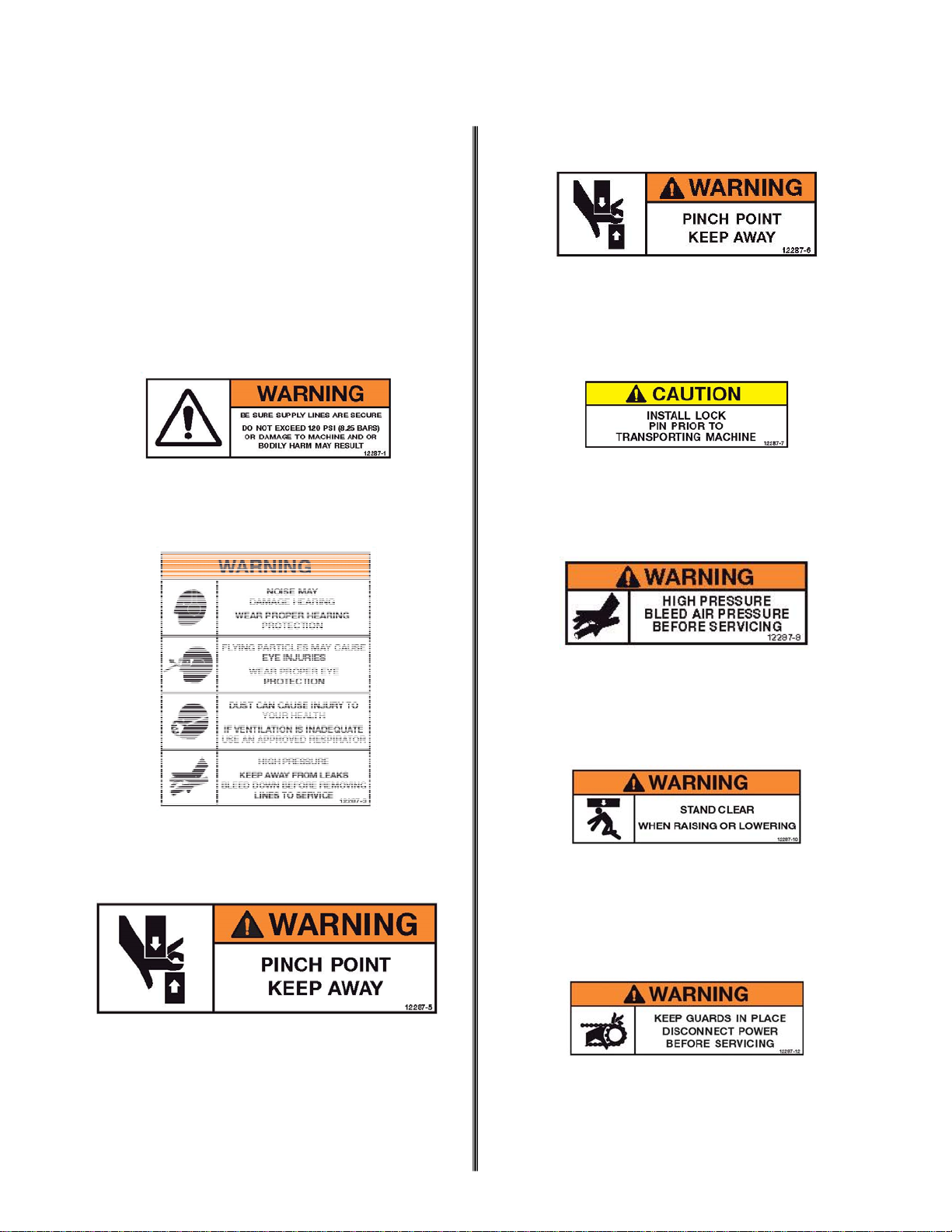
eye and hearing protection. Dust mask,
non-skid safety shoes, hard hat, and/or
hearing protection must be used for ap-
propriate conditions. Prolonged expo-
sure to loud noise can cause impair-
ment or loss of hearing. Wear suitable
hearing protection devices such as ear-
muffs or earplugs.
6. Keep a first-aid kit near the machine.
Safety depends on you.
TOOL USE AND CARE
1. Only qualified persons should operate
the machine. Make sure you operate
and service your machine according to
the instructions listed in this manual.
2. When positioning the machine for drill-
ing, always face the drill. DO NOT op-
erate with your back to the machine.
Facing the machine during positioning
allows the operator to have better con-
trol of the machine.
3. DO NOT force the machine. Use the
correct machine for your application.
The correct machine will do the job bet-
ter and safer at the rate for which it is
designed.
4. DO NOT use the machine if the switch
does not turn it on or off. Any machine
that cannot be controlled with the
switch is dangerous and must be re-
paired.
5. Disconnect the machine from the pow-
er source before making any adjust-
ments, changing accessories or storing
the machine. Such preventative safety
measures reduce the risk of starting
the machine accidentally.
6. Store machines out of reach of children
and other untrained persons. Machines
are dangerous in the hands of un-
trained users.
7. Maintain machines with care and keep
them clean. Properly maintained ma-
chines are less likely to bind and are
easier to control.
8. Check for misalignment or binding of
moving parts, breakage of parts and
any other condition that may affect the
machines operation. If damaged, have
the machine serviced before using.
Many accidents are caused by poorly
maintained tools.
9. Use only accessories that are recom-
mended by the manufacturer for your
model. Accessories that may be suita-
ble for one machine may become haz-
ardous when used on another.
SERVICE
1. DO NOT run the drill unit while you
make adjustments and repairs unless
the procedure is approved.
2. Escaping fluid and air under pressure
can have sufficient force to penetrate
skin causing serious personal injury.
3. Before disconnecting lines, be sure to
relieve all pressure. Before applying
pressure to the system, be sure all
connections are tight and that lines,
tubes and hoses are not damaged.
4. DO NOT use your hand to search for
leaks. Instead, use a piece of card-
board or wood.
5. Tool service must be performed only by
qualified repair personnel. Service or
maintenance performed by unqualified
personnel could result in injury or
death.
6. When servicing a tool, use only identi-
cal replacement parts. Use of unau-
thorized parts increase injury risk.

Form: MM-A-1C/A-2C Revised: 1-8
Safety Decal Location
AllsafetylabelsonMinnichManufacturingunitshave
beencarefullyplacedsotheycanbeeasilyseenatall
mes.Thereareseveraldifferenttypesoflabelson
theunits.Alwayskeepthesewarningsfreeofdirt,
concrete,oranythingelsethatrestrictsvisibility.Nev-
erremovethelabelsforanyreason.Ifthelabelson
yourmachinebecomewornorinanywaydifficultto
read,callourpartsdepartmentforreplacements.
A
B
C
D
E
F
G
H
012287-00008
012287-00005
012287-00006
012287-00003
012287-00001
012287-00010
012287-00007
012287-00012

Form: MM-A-1C/A-2C Revised: 1-9
Safety Decal Location
I
J
012287-00062
012287-00064

Form: MM-A-1C/A-2C Revised: 1-10
A-1C Safety Decal Location
D
D
D
D
F A
H
B
G I
C
J
G
E

Form: MM-A-1C/A-2C Revised: 1-11
A-2C Safety Decal Location
E E
G B F
D D
H

Form: MM-A-1C/A-2C Revised: 1-12
A-2C Safety Decal Location
D
D
D
A
I
C J J
G
C C

Form: MM-A-1C/A-2C Revised: 2-1
PRESSURE REGULATOR—002880-00000
OPERATION
A regulator is used in a compressed air system
to maintain nearly constant outlet pressure de-
spite changes in the inlet air pressure and chang-
es in downstream flow requirements.
Outlet pressure is controlled by the adjusting
screw. Clockwise rotation increases and counter-
clockwise rotation decreases outlet pressure set-
ting. When the adjustment screw is rotated fully
counterclockwise, no force is applied to the regu-
lating spring and the valve is held closed by the
valve spring . Clockwise rotation of the adjust-
ment screw compresses the regulating spring
which applies a downward force on top of the di-
aphragm. The diaphragm and valve pin move
downward forcing valve off its seat which allows
air to flow through the regulator to the down-
stream system.
Outlet pressure increases in the downstream
system and sensing chamber and applies an up-
ward force on bottom of the diaphragm. The dia-
phragm, valve pin, and valve move upward, com-
pressing the regulator spring. Upward movement
stops when the forces below the diaphragm bal-
ance the forces above the diaphragm. When
there is no downstream flow demand, the bal-
ance of forces occurs with the valve closed.
When there is downstream flow demand, the bal-
ance of forces occurs when the valve opens suf-
ficiently to compensate for demand, thus main-
taining the desired outlet pressure.
ADJUSTMENT
1. Before turning on system air pressure, turn
regulator adjustment screw counterclockwise
until all load is removed from regulating
spring.
2. Turn on system air pressure.
3. Turn regulator adjustment clockwise until the
desired outlet pressure is reached.
4. To avoid minor readjustment after making a
change in pressure setting, always approach
the desired pressure from a lower pressure.
When reducing from a higher to a lower set-
ting, first reduce to some pressure less than
the desired and bring up
to the desired point.
5. Tighten jam out to lock
pressure setting.
MAINTENANCE
The regulator can be disas-
sembled for servicing with-
out removal from pipe line.
To disassemble, shut off the
inlet air and reduce pressure
in inlet and outlet lines to ze-
ro. Turn adjusting screw counterclockwise until
all load is removed from regulating spring. Re-
move bonnet screws, bonnet, upper springrest,
spring and diaphragm assembly. Unscrew and
remove bottom plug, o-ring, and valve spring.
Pull valve assembly together with o-ring out of
body. Do not remove valve seat unless replace-
ment is necessary. Remove o-ring using a hook
shaped tool, taking care not to damage o-ring
seating surfaces or valve seat.
Clean parts using warm water and soap. Dry
thoroughly. Inspect each part carefully. Replace
any parts which are damaged.
At reassembly, apply a wipe coat of silicone
based grease to O-rings, stem and body of valve
assembly, and center bore in bottom plug. Apply
a light even coat of light grease to full length of
threads and tip of adjusting screw. Tighten valve
seat, if previously removed, to 80-100 inch-
pounds torque (9-11.3N-m). Tighten bottom plug
snugly by hand. Tighten bonnet screws to 20-30
inch-pounds torque (2.3-3.4N-m).
These regulators are intended for use in industri-
al compressed air systems only. Do not use
these regulators where pressure or temperature
can exceed rated operating conditions. If outlet
pressure in excess of the regulator pressure set-
ting could cause downstream equipment to rup-
ture or malfunction, install a pressure relief de-
vice downstream of the regulator. The relief pres-
Chapter 2—Controls and Gauges
WARNING!

Form: MM-A-1C/A-2C Revised: 2-2
LUBRICATOR—001864-00000
SPECIFICATIONS
Capacity: 0.5 pint (237mL)
Pipe Size: 3/4 in NPT (1.9 cm)
ADJUSTMENT
Lubricator is set at 5.5 from factory. Different
temperatures may affect flow or oil. You might
have to adjust the lubricator accordingly. Be sure
the lubricator is set so that you always have a
light film of oil on the exhaust deflector.
To adjust the lubricator, disconnect air pressure
from the drill unit. Push down on pressure reliev-
ing button on fill cap. Remove fill cap. Using a
screw driver, adjust lubricator to required setting.
To increase oil, set at a higher number. To de-
crease oil. Set at a lower number.
Chapter 2—Controls and Gauges
Part Number Item Description
001864-00001 1 Feeder Assembly Kit
001864-00002 2 Manual Relieving Safety Cap
001864-00003 4 Sight Window
001864-00004 6 Check Valve (Constant Feed)
006412-00916 Filler Cap O-Ring
006412-00905 Feeder O-Ring

Form: MM-A-1C/A-2C Revised: 3-1
1. Make sure that the lubricator is full. See the
recommended lubricants below.
2. Use a 3/4” (19mm) hose to supply air to the
drill unit for A-1C series units and 1-
1/4” (31.75mm) hose for A-2C series units.
3. Install the drill steel and bit into the drill.
4. Make sure that the air compressor is on.
5. Position the drill where the first hole is to be
drilled and set the brake.
6. Remove the rail locking pin and, using the lift
valve, lower the rail to the horizontal drilling posi-
tion.
7. If the rail is not parallel to the surface of the
slab, loosen the jam nut in the cylinder end ad-
juster and turn the cylinder shaft one way or the
other until the rail is parallel with the slab. Re-
tighten the jam nut.
8. Make sure the rub strip is against the slab.
9. Using the height adjusting screw, adjust the
height to the required distance from the top of the
slab to the center of the hole.
10. Remove the slider lock pin using the feed lev-
er. Feed the drill bit tight against the slab. Meas-
ure from the end of the drill stop rod to the stop
pad and adjust the depth accordingly.
11. Make sure that the regulator is set between
18 - 22 PSIG (1.24 - 1.52 bar).
12. Using the drill control valve, drill the hole until
the stop rod is against the stop pad. Measure the
actual hole depth and adjust the stop rod accord-
ingly.
13. You are now ready to start drilling.
Chapter 3—Standard Setup
Ambient Temperature (Equivalent SAE)
Supplier Below 4°C 4°C—36°C Above 36°C
AGIP Rock Drill RD100
Caltex RPM Vistac Oil 32X or
Rock Drill Lube 46
RPM Vistac Oil
100X
RPM Vistac Oil
320X
Texaco Rock Drill Lube 46 Rock Drill Lube 100 Rock Drill Lube 320
Chevron Vistac Oil 32X Vistac Oil 100X Vistac Oil 320X
Mobil Almo Oil No. 1 Almo Oil No. 2 Almo Oil No. 5
Shell Shell Tona Oil R100 Shell Tona Oil R320 (150)
***DO NOT USE ENGINE OIL, DIESEL OR HYDRAULIC FLUID***
RECOMMENDED LUBRICANTS

Form: MM-A-1C/A-2C Revised: 3-1
UNLOADING THE UNIT
If you’re A-1C/A-2C unit is on a truck bed or oth-
er platform and needs to be lifted into position,
use the **********
FILLING LUBRICATOR
Prior to filling the lubricator, be sure
there is no air pressure in the unit. Failure to re-
lieve air pressure will result in the fill plug explod-
ing from the lubricator, which may result in injury.
Remove fill plug and fill with lubricant until sight
gauge is full. Replace fill plug. Lubricator should
be filled every two hours of use for an A-1C and
every four hours of use for an A-2C. See Recom-
mended Lubricants chart on page XX for ac-
ceptable lubricants.
MACHINE INSPECTION
Prior to each use, it is imperative to inspect the
machine all over to ensure excellent condition for
the safety of the operator and to prevent damage
to the equipment.
Check all drill bed bolts and tighten as neces-
sary on a daily basis. Tighten all other bolts at
least once weekly. Refer maintenance dia-
gram on page 5-1.
Grease fittings around drill bed daily. Grease
all other fittings at least once a week. Refer
maintenance diagram on page 5-1.
Verify that all lock pins are in their locked po-
sition.
Make sure all controls are in the “off” position
and the lift lever is in the “up” position.
Check that the air line is cleaned out and is
the proper size and pressure rating.
Ensure the air compressor is set at an operat-
ing pressure of not more than 120 PSI
(8.27bar).
Install drill steel and bits into the drill motors
and close the latch retainers and rod guides.
AIR COMPRESSOR CONNECTION
Connect the air line to the drill in accordance
with hose connection instructions in the com-
pressor manual.
Start the compressor according to manufac-
turer’s instructions.
POSITION MACHINE FOR DRILLING
Position the drill unit where the first set of
holes is to be drilled, keeping the drill unit
back from the edge of the slab slightly. Set
the brake.
With the lift lock still engaged, charge the lift
cylinder by toggling the lift lever up and down.
With the lift valve in the “up” position and after
making sure that there are no obstructions in
the path of the drill bed, remove the lift lock
pin.
Using the lift lever, lower the drill bed into
drilling position.
HEIGHT ADJUSTMENT
To check the drilling height, measure from the
top of the slab to the center of the drill steel. If
necessary, loosen the locknuts and use the ad-
justing screws to raise or lower the drill bed into
the proper drilling height. After height is properly
adjusted, re-tighten the locknuts.
Verify the drill bed is parallel with the slab that is
to be drilled into. If necessary, loosen the locknut
on the lift cylinder and turn the adjusting screw
right to raise the bed or left to lower the bed
until the bed is parallel with the slab. Re-tighten
locknuts after complete.
DEPTH ADJUSTMENT
Physical motion is going to occur,
stand clear of the drill unit.
To set the drill depth, remove all of the rail lock-
ing pins and feed the drill bit into the face of the
slab without turning on the drills by turning on
Feed 1 and the feed switch. Repeat for Feed 2,
when applicable. Measure the distance between
Chapter 3—Standard Setup
WARNING!
CAUTION!
CAUTION!

Form: MM-A-1C/A-2C Revised: 3-2
the drill stop rod and the drill stop pad. Adjust the
stop bolt so that the distance between the stop
pad and the stop bolt equals the drill depth.
DRILL TEST HOLE
Refer to operating instructions to drill the first set
of holes. After the first set of holes, measure the
height and depth of the hole to ensure proper
alignment.
Chapter 3—Standard Setup

Form: MM-A-1C/A-2C Revised: 4-1
1. Make sure the lubricator is full. See recom-
mended lubricants on page 3-1. A-1C series
units should be filled every two hours. A-2C se-
ries units should be filled every four hours.
2. Use a 3/4” (19mm) hose to supply air to the
drill unit for A-1C series units and 1-
1/4” (31.75mm) hose for A-2C series units.
3. Install the drill steel and bit into the drill.
4. Make sure the air compressor is on.
5. Position the drill where the first hole is to be
drilled and set the brake.
6. Remove the rail locking pin.
7. Lower the rail to the horizontal drilling position.
8. Make sure the rub strip is against the slab.
9. Using the feed control valve, feed the bit
against the slab.
10. Using the drill control valve, feed the bit
against the slab.
11. With the drill valve turned on and the feed
switch turned on, the slider and drill will move
and the drill will turn on. When the feed switch is
turned off, the slider is retracted from the hole
and the drill will turn off automatically. If it does
not, turn the drill switch off.
12. Once the hole is drilled, disengage the brake
and move the unit to the next hole location, en-
gage the brake, and repeat steps 8-11 as neces-
sary.
Chapter 4—Drilling Operations
This manual suits for next models
3
Table of contents
Other Minnich Construction Equipment manuals
Popular Construction Equipment manuals by other brands

Husqvarna
Husqvarna SMART 40 Safety and operating instructions

Manitowoc
Manitowoc National Crane 1300A Service and maintenance manual

Sealey
Sealey DF760.V2 instructions

Grouser Products
Grouser Products V3 Flex Plane Owner's and operator's manual

ATD Tools
ATD Tools ATD-7484 Operating instructions & parts manual

Tadano
Tadano GR-1000XLL-4 manual