Minuteman E1000RM1U User manual

1-866-207-6631 | www.rackmountsolutions.net
sales@rackmountsolutions.net

1
© Copyright Para Systems, Inc., 2005
Enterprise 1U Rackmount Series User's Manual
1. Introduction 2
2. Controls and Indicators 6
3. Installation 8
4. Operation 12
5. Troubleshooting 15
6. Replacing the Battery 16
7. Obtaining Service 19
8. Specifications 20
9. Configurable Parameters & Settings 22
10. Limited Product Warranty 23
11. Declaration of Conformity 25
English

2
IMPORTANT SAFETY INSTRUCTIONS
SAVE THESE INSTRUCTIONS !
English
ThankyouforpurchasingaMINUTEMANpowerprotectionproduct.Ithasbeen
designedandmanufactured toprovidemany yearsoftrouble freeservice.
Please read this manual before installing your Enterprise 1U Rackmount Se-
ries UPS, models E700RM1U, E1000RM1U, E1500RM1U, as it provides im-
portantinformationthatshouldbefollowed during installationandmaintenance
of the UPS and batteries allowing you to correctly set up your system for the
maximum safety and performance. Included is information on customer sup-
port and factory service if it is required. If you experience a problem with the
UPS please refer to the Troubleshooting guide in this manual to correct the
problemorcollectenoughinformation so thattheMINUTEMANTechnicalSup-
port Department can rapidly assist you.
Thissymbol indicates "ATTENTION"
This symbol indicates "Risk of Electrical Shock"
This symbol indicates "Alternating Current Supply"
This symbol indicates "Alternating Current Supply Phase"

3
WARNING: Riskof ElectricalShock. Hazardous live parts inside
these power supplies are energized from the battery even when the
AC input is disconnected.
CAUTION! Tode-energize the outputsof theUPS:
1. If the UPS is on press and release the On/Off/Test button.
2. Disconnect the UPS from theAC wall outlet.
3. To de-energize the UPS completely, disconnect the battery.
CAUTION! To reduce the risk of electrical shock in conditions
where the load equipment grounding cannot be verified, disconnect
theUPSfromtheACwalloutlet before installingacomputer interface
cable. Reconnectthepower cordonlyafter allsignalingconnections
aremade.
CAUTION! Connect the UPS to a two pole, three wire grounding
ACwalloutlet. The receptaclemust beconnectedto theappropriate
branch protection (circuit breaker or fuse). Connection to any other
type of receptacle may result in a shock hazard and violate local
electricalcodes. Donotuse extension cords,adapterplugs,or surge
strips.
English
CAUTION! Toreduce the risk ofelectrical shock with the installa-
tion of this UPS equipment and the connected equipment, the user
must ensure that the combined sum of the AC leakage current does
not exceed 3.5mA.
This symbol indicates "Direct Current Supply"
This symbol indicates "Equipment Grounding Conductor"
WARNING: ThisUninterruptiblePowerSupplycontainspotentially
hazardousvoltages. Donot attemptto disassemblethe UPS beyond
the battery replacement procedure. This UPS contains no user ser-
viceableparts. Repairs andBattery replacementmust be performed
byQUALIFIED SERVICEPERSONNELONLY.

4
English
Afterremoving your MINUTEMAN UPS from its carton,it should be inspected
fordamage thatmay haveoccurred inshipping. Immediately notify the carrier
and place of purchase if any damage is found. Warranty claims for damage
causedbythecarrier willnotbehonored. The packingmaterialsthatyour UPS
wasshippedin arecarefullydesigned to minimizeany shipping damage.In the
unlikely case that the UPS needs to be returned to MINUTEMAN, please use
the original packing material. Since MINUTEMAN is not responsible for ship-
pingdamage incurredwhen thesystem isreturned, theoriginal packingmate-
rialisinexpensive insurance. PLEASE SAVE THE PACKING MATERIALS!
Receiving Inspection
NOTICE: This equipment has been tested and found to comply with
thelimitsfor a ClassAcomputingdevice in accordancewith thespeci-
ficationsinSubpartJof Part15of FCCRules and theClassAlimitsfor
radionoiseemissionsfromdigitalapparatus setoutintheRadioInterference of
the Canadian Department of Communications. These limits are designed to
providereasonableprotectionagainstsuchinterferenceinaresidentialinstalla-
tion. This equipment generates and uses radio frequency and if not installed
andused properly,thatis, instrict accordancewith the manufacturer's instruc-
tions,this equipment maycause interferenceto radioand televisionreception.
Ifthisequipmentdoescause interferencetoradioortelevision reception, which
canbedeterminedby turningtheequipmentoff andon,theuser isencouraged
to try to correct the interference by one or more of the following measures:
Re-orientthereceivingantenna.
Relocatethe computerwith respect tothe receiver.
Movethecomputer away fromthereceiver.
Plugthe computerinto a differentoutlet sothat the computerand receiver
areon differentbranch circuits.
Shieldedcommunicationsinterface cablesmustbe usedwith thisproduct.
WARNING: Changes or modifications to this unit not expressly ap-
proved by the party responsible for compliance could void the user's
authorityto operatethe equipment.
NOTE: TheseUPSs areshipped withthe batteriesdisconnected. The batter-
ies must be connected before putting these UPSs into service. Refer to Sec-
tion 3 "Installation" for connecting the batteries.

5
English
Para Systems Life Support Policy
As a general policy, Para Systems Inc. (Para Systems) does not recommend
the use of any of its products in life support applications where failure or mal-
function of the Para Systems product can be reasonably expected to cause
failure of the life support device or to significantly affect its safety or effective-
ness. Para Systems does not recommend the use of any of its products in
directpatient care. ParaSystems will notknowingly sellits products foruse in
such applications unless it receives in writing assurances satisfactory to Para
Systems that (a) the risks of injury or damage have been minimized, (b) the
customer assumes all such risks, and (c) the liability of Para Systems Inc. is
adequatelyprotected underthe circumstances.
Examplesofdevicesconsideredtobe lifesupportdevicesareneonataloxygen
analyzers,nerve stimulators (whetherused foranesthesia, painrelief, orother
purposes), auto transfusion devices, blood pumps, defibrillators, arrhythmia
detectorsand alarms,pacemakers, hemodialysissystems, peritoneal dialysis
systems,neonatal ventilator incubators,ventilators forboth adultsand infants,
anesthesiaventilators,and infusionpumps aswellas anyother devices desig-
nated as “critical” by the United States FDA.
Hospitalgrade wiring devices and leakage current may be orderedas options
on many PARA SYSTEMS UPS systems. PARA SYSTEMS does not claim
that units with this modification are certified or listed as Hospital Grade by
PARA SYSTEMS or any other organization. Therefore, these units do not
meet the requirements for use in direct patient care.

6
English
TheAC normal (green) LED illuminates in a steady state when the
UPS is on and operating in the AC normal mode. The AC normal
LED will extinguish when operating in the Battery mode.
TheOn-Battery (green) LED illuminates in a steady statewhen the
UPS is operating in the Battery mode. The On-Battery LED will
extinguishwhenoperatinginthe ACnormal,BoostandBuckmodes.
The Boost (yellow) LED illuminates in a blinking state when the
UPSisoperating inthe Boostmode. The Boost LEDwill extinguish
when operating in theAC normal, Buck and Battery modes.
TheBuck(yellow) LEDilluminates inablinking statewhen theUPS
isoperating in the Buckmode. The Buck LED willextinguish when
operating in theAC normal, Boost and Battery modes.
The Fault (red) LED illuminates in a steady state when the UPS
detects an internal fault. The Fault LED is extinguished when the
UPSis operatingproperly.
TheWeak/BadBattery (red) LEDilluminatesin asteadystate when
the UPS detects a weak battery, bad battery or if the battery is
disconnected. The Weak/Bad Battery LED is extinguished when
the battery's condition is good.
The Site Wiring Fault (red) LED illuminates in a steady state when
theUPSdetects asitewiring problem. TheSiteWiring FaultLED is
extinguished when the UPS is connected to proper site wiring.
CONTROL PANEL

7
English
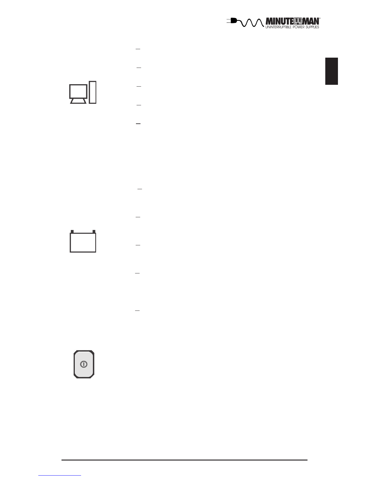
TheLoadLevel BarGraphoperates as follows:
LED#10: >10% load(green/red/yellow) LEDwill begreen and illu-
minated when there is at least 10% of the rated capacity.
LED #30: >30% load (green/yellow) LED will be green and illumi-
nated when there is at least 30% of the rated capacity.
LED #50: >50% load (green/yellow) LED will be green and illumi-
nated when there is at least 50% of the rated capacity.
LED #70: >70% load (green/yellow) LED will be green and illumi-
nated when there is at least 70% of the rated capacity.
LED #90: >90% to approximately 109% load (red/yellow) LED will
be yellow and illuminated when there is approximately 90% of the
rated capacity to indicate that unit is near full capacity. The LED
will turn red at 110% load capacity to indicate an Overload condi-
tion.
TheBattery CapacityBar Graph operatesas follows:
LED #90: >90% battery capacity (red/yellow) LED will be yellow
and illuminated until the battery’s capacity drops below 80% ca-
pacity and then it will extinguish.
LED#70: >70% batterycapacity (green/yellow) LEDwill beyellow
and illuminated until the battery’s capacity drops below 60% ca-
pacity and then it will extinguish.
LED#50: >50% batterycapacity (green/yellow) LEDwill beyellow
and illuminated until the battery’s capacity drops below 40% ca-
pacity and then it will extinguish.
LED#30:>30% batterycapacity(green/red/yellow)LEDwill beyel-
low and illuminated until the battery’s capacity drops below 30%
capacity and then it will turn red. When the battery capacity drops
below 20% capacity the LED will extinguish.
LED#10:>30% batterycapacity(green/red/yellow)LEDwill beyel-
low and illuminated until the unit issues a Low Battery Warning
Alarm and then it will turn red to indicate a Low Battery Warning.
TheMulti-Function On/Off/TestButton functionsas follows:
When the UPS is Off, press and release the On/Off/Test button
after one beep to turn the UPS On.
When the UPS is On, press and release the On/Off/Test Button
afterone beep to turn the UPSOff.
WhentheUPS is On,pressand holdtheOn/Off/Testbutton for four
beeps, then release the button. The UPS will perform a 5-second
SelfTest.

8
English
INSTALLATION PLACEMENT
TheEnterprise 1URackmount Seriesis intendedto beinstall ina temperature
controlled environment that is free of conductive contaminants. Select a loca-
tion which will provide good air circulation for the UPS at all times.Avoid loca-
tions near heating devices, water or excessive humidity, or where the UPS is
exposedto direct sunlight.Route power cordsso they cannot be walked on or
damaged.
OperatingTemperature (Maximum): 0to 40degreesC (+32to 104degreesF)
OperatingElevation: 0 to 3,000m (0to 10,000 ft)
OperatingandStorage RelativeHumidity: 95%,non-condensing
Storage Temperature: -15 to +45 degrees C (+5 to +113 degrees F)
Storage Elevation: 0 to 15,000m (0 to +50,000 ft)
REAR PANEL
1.The input power cord has a NEMA 5-15P Plug.
2. The input circuit breaker will trip in the event the load exceeds the UPS’s
power rating.
3.The Battery Backup output power receptacles are NEMA 5-15Rtype. The
output receptacles are electrically wired into two segments to support the
"LoadShedding Function". Thethree receptacles onthe left areSegment 1
and the three receptacles on the right are Segment 2.
4.The RS232Communications InterfacePort is for UPS monitoringand con-
trol.
5.TheR-J11/R-J45 modular connectorsareused for10/100Base-TNetwork/
single line Phone/Fax/Modem protection.
6.The USBCommunications InterfacePort is forUPS monitoringand control.
7.TheDipswitches arefor settingthe Inverter(On-Battery)output voltage.
8.The option slotwill support MINUTEMAN option cards only.

9
English
INSTALLATION
Besure toread theinstallation placementand allthe cautionsbefore installing
the UPS. Place the UPS in the final desired location and complete the rest of
theinstallation procedure. TheseUPSs areshipped withthe internalbatteries
disconnected. The batteries must be connected before putting these UPSs
into service. Follow the procedure below to connect the batteries and install
theUPS into the rack. USE CAUTION: The UPS is heavy. Use the appropri-
atenumber ofpersonnel wheninstalling the UPS.
Connecting the Batteries
1. Remove the UPS from the shipping box and set on the floor or a bench top.
2. Grasp the front panel and gently pull it off the UPS. (FIG. 1)
3.Remove the four retainingscrewsfor the batteryretainingbracket. (FIG.2)
4.Remove the battery retainingbracket. (FIG.2)
5.Graspthe batterytray and gentlypull thebatterytray outfar enoughtoget to
the battery connectors (red and black). (FIG. 3)
6.Connect the batteryconnectors (red andblack) together.
7. Gently slide the battery tray back into the UPS.
8. Re-install the battery retaining bracket.
9.Re-install the fourretaining screws forthe battery retainingbracket.
10. Re-install the front panel onto the UPS.
FIG. 1 FIG. 2
FIG. 3

10
English
Installing the UPS in a 4-post rack
USE CAUTION: TheUPS isheavy. Usetheappropriate number ofpersonnel
when installing the UPS.
1. Install the rails in the 4-post rack. (FIG. 1)
2. Install the rack ears on the UPS. (FIG. 2)
3.Align the cleats with the rails and slide the UPS into the rails. (FIG. 3)
NOTE: Thecleats arepre-mounted on theUPS.
4. Secure the UPS to the rack with the retaining screws (not provided). The
UPS is ready for normal operation, see connecting your equipment.
Installing the UPS in a 2-post rack
USE CAUTION: TheUPS isheavy. Usetheappropriate number ofpersonnel
wheninstallingthe UPS. MINUTEMAN recommendsthatthe UPSbeinstalled
at the bottom of the rack and that the rack ears be installed as FIG. 4.
1. Install the rack ears on the UPS. (FIG. 4)
NOTE: If you are installing the rack ears in the middle of the UPS, the pre-
mountedcleats willhave to be removed fromthe UPS.
2. Secure the UPS to the rack with the retaining screws (not provided). The
UPS is ready for normal operation; see connecting your equipment.
FIG. 1 FIG. 2
FIG. 3 FIG. 4

11
English
CHARGINGTHEBATTERY
The Enterprise 1U Rackmount Series UPS will charge the internal batteries
whenever the UPS is connected to anAC source. It is recommended that the
UPS's batteries be charged for a minimum of 4 hours before use. The UPS
maybeused immediately,however, the “On-Battery”runtime maybeless than
normallyexpected. NOTE: IftheUPS isgoingto beoutof service orstoredfor
aprolonged period oftime, thebatteries mustbe rechargedfor atleast twenty-
fourhours every ninety days.
CHECKINGTHE SITE WIRING FAULT
After plugging in the UPS, check the Site Wiring Fault (SWF) LED on the
control panel of the UPS. If the SWF LED is illuminated, the UPS is plugged
into an improperly wired AC outlet. If the UPS indicates a Site Wiring Fault
(SWF),have aQualified Electrician correct the problem.
COMMUNICATIONS PORT CONNECTION(OPTIONAL)
MINUTEMANPowerMonitoringSoftwareandinterfacecableskitscanbeused
with the Enterprise 1U Rackmount Series UPS. Use only MINUTEMAN or
MINUTEMANapproved interface cableswith these UPSs. Connectthe inter-
facecable (Serial or USB)to the appropriate communicationsport on the rear
panelof the UPS. Connectthe other endof the cable to the device that will be
monitoring/controlling the UPS. NOTE: Connecting to the Communications
Port is optional. The UPS works properly without this connection.
CONNECTINGTHEUPSTO AN AC SOURCE
PlugtheUPS intoatwo pole,threewire, groundedreceptacleonly. Donotuse
extension cords, adapter plugs, or surge strips.
NETWORK/PHONE/FAX/MODEMPROTECTIONCONNECTION(OPTIONAL)
Connecta10/100 Base-Tnetwork,single linephone, Fax orModem linetothe
RJ11/45protectionsockets on the rear panel ofthe UPS. This connection will
require another length of telephone or network cable. The cable coming from
the telephone service or networked system is connected to the port marked
“IN”. The equipment to be protected is connected to the port marked "OUT".
NOTE: Connectingto theNetwork/Phone/Fax/Modem protectionsocket con-
nection is optional. The UPS works properly without this connection.
CONNECTINGYOUREQUIPMENT
Plug the equipment into the output receptacles on the rear panel of the UPS.
Do not use extension cords, adapter plugs or surge strips on the output of the
UPS. Ensure that you do not exceed the maximum output rating of the UPS
(referto theinformation labelon theUPS orthe ElectricalSpecificationsin this
manual).
CAUTION! DO NOT connectalaserprinterto theoutputreceptacles on the
UPS,unlessthe UPSis rated2000VAorgreater. Alaserprinter
draws significantly more power when printing than at idle and
mayoverloadthe UPS.

12
English
SYSTEMOVERVIEW
ThisLine-Interactive 1U Rackmount model UPS protects internetworking and
telecommunicationsequipment from blackouts, brownouts, overvoltages,and
surges. TheAVR function continuously corrects the voltages, in-between the
brownoutandovervoltagetransferpoints(85 -150VAC), toasafe usable level.
When the UPS is operating in the AVR mode the audible alarm will remain
silent and the Boost or the Buck indicator will blink. During normalAC opera-
tion, the MINUTEMAN UPS will quietly and confidently protect your system
frompoweranomalies.
TheUPS willcharge thebatteries withthe UPS in the onor offposition aslong
astheUPSisplugged intothewalloutletand thereisanacceptableACvoltage
present. When a blackout, brownout, or an overvoltage condition occurs; the
UPS will transfer to the battery mode, the On-Battery indicator will illuminate
and the audible alarm will sound once every ten-seconds indicating that the
commercial power is lost or unacceptable. When the commercial power re-
turns or is at an acceptable level, the UPS will automatically transfer back to
the AC normal mode and start recharging the batteries. During an extended
outagewhenthere isapproximately two-minutesofbackup timeremaining the
audiblealarmwillsoundtwiceevery five-seconds. This LowBatteryWarningis
letting the user know that they should save all open files and turn off their
computer. When the batteries reach the pre-determined level the UPS will
automatically shutdown protecting the batteries from over discharging. Once
thecommercialpowerreturns theUPSwillautomatically restart,providingsafe
usablepower tothe connected equipmentand startrecharging the batteries.
TURNING THE UNIT ON/OFF
On / Off / Test Button
Press and release the On/Off/Test Button after one beep to turn the UPS on
andsupplypower tothe load. Theloadis immediatelypowered whiletheUPS
runsafive-secondselftest. Pressand release theOn/Off/TestButton afterone
beepto turnthe UPS off. TheUPS willcontinue to chargethe batterieswhen-
ever it is plugged into a wall outlet and there isAC present.

13
English
ALARMS
ONBATTERY
Whenthe UPS isoperating onthe batteries,the On-Battery LEDwill illuminate
and the audible alarm will sound once every ten-seconds. The alarm will stop
once the UPS returns to theAC normal mode.
LOWBATTERYWARNING
The UPS will sound two beeps every five-seconds when the battery reserve
runs low. This condition will continue untilAC returns or the UPS shuts down
frombattery exhaustion.
DIP SWITCH SETTINGS
TheDIP Switchsetting maybe changedby theuser toset thedesired Inverter
(On-Battery)outputvoltage.The DIP Switchmustbeset tothedesiredInverter
(On-Battery)outputvoltage andthenthe UPSmustbe turnedoffand restarted
to reconfigure the microprocessor and save the changes. The Inverter (On-
Battery)outputvoltagesettingcanbeeither120VAC(default)or127VAC. Chang-
ing the Inverter (On-Battery) output voltage to 127VAC, will also change the
Bucksetpoint from130VAC (default) to 137VAC.
Switch 1 2
120V (Off) (On)
127V (On) (Off)
SELFTEST
Theself testfeature isuseful toverify thecorrect operationof theUPS andthe
condition of the batteries. With the UPS in the AC normal mode, press and
hold the On/Off/Test Button for four beeps, then release the button. The UPS
will perform a ten-second self test. During the self test, the UPS will switch to
batterypowerand theOn-BatteryLED willilluminate and theaudible alarmwill
sound. Thelength ofthe testthat isautomatically performed every two weeks
is longer than the start-up or user invoked test. This test will run for approxi-
mately fifteen-seconds to measure the battery’s capability to provide an ac-
ceptable amount of runtime. If the UPS fails a self test, one of the LEDs will
remain illuminated indicating the type of problem. NOTE: The UPS will auto-
matically perform a self test on start-up and every two weeks.
UPSFAULT
When the UPS detects a hardware fault, the Fault LED will illuminate and the
UPSwill sound aconstant alarm. The faultcondition, in some instances, may
be reset by turning the UPS off and then on.
Inverter(On-Battery)outputvoltage
LOADSHEDDING FUNCTION
Theoutput receptacles are electrically wired into twosegments to support the
"LoadSheddingFunction". The usercancontrol the twosegments individually
or both at the same time. The Load Shedding Function is controllable by the
PowerMonitoring Softwareor theSNMP card.

14
English
COMMUNICATIONS PORTS (RS232andUSB)
TheRS232communicationportisastandardDB9 female withbothRS232and
simulated contact closure capability. The Enterprise 1U Rackmount Series
UPS will poll the port and activate the port for RS232 or contact closure in
accordancewith thetype ofcable itfinds connectedto theport. Tochangethe
portconfiguration requiresthe unitbe turnedoff and restarted with thedesired
cable connected. The pinout for the port is depicted per the chart below.
Pin1: EPO Emergency Power Off(momentarily pull this pin low to completely
turn off the UPS in any mode. The UPS will have to be turned off and then
turned back on to restart the unit)
Pin2:/TXD
Pin3:/RXD andreceive UPSshutdown command
Pin 4: Simulated contact closureAC fail, NO
Pin5: Ground
Pin 6: Simulated contact closure Low Battery Warning, NO
Pin 7: Simulated contact closureAC fail, NC
Pin 8:AC fail signal (high to low signal)
Pin 9: Not Used
WEAK/BADBATTERY
TheUPSautomaticallyteststhebattery’sconditionandwillilluminatetheWeak/
Bad Battery LED and sound the alarm. This alarm will be repeated until the
batteries pass a self test. If the battery is weak, bad or disconnected, the
Weak/BadBatteryLEDwill illuminateandthealarm willbeepthreetimes every
five-minutes until the battery is reconnected or replaced. It is recommended
thattheUPS beallowedto chargeovernightbefore performingabattery testto
confirm a Weak/Bad Battery condition.
NOTE: IftheUPS hasa Weak/BadBatteryAlarm afterreconnectingor replac-
ing the batteries, the user must initiate a self test to clear the Weak/Bad Bat-
teryAlarm. To initiate a self test see section 4 "SELF TEST".
OVERLOAD
When the amount of load attached to the UPS exceeds its power rating, the
Overload LED will illuminate and the UPS will sound a constant alarm. This
alarmwill remain on until theexcess load isremoved or theUPS’s self protec-
tion circuit shuts the UPS down.
POWERMONITORING SOFTWARE
TheUPScomes withaMINUTEMAN PowerMonitoringSoftware CD. See the
softwareCDfortheinstallationoftheMINUTEMANPowerMonitoringSoftware.
USBPORT
TheUSB port will support the MINUTEMAN Power Monitoring Software. See
thesoftware CD forthe USB installation.
OPTION SLOT
Theoptionslot onthe rear panelof theUPSwill onlysupport the MINUTEMAN
optioncards.

15
English
PossibleCause
Symptom What To Do
PressandreleasetheOn/Off/
Test button to start UPS
On/Off/Test button not
pushed
UPSwill not turn on
Reset circuit breaker by
pressing the plunger back in.
If the AC circuit breaker trips
after UPS starts up, reduce
the load on the UPS
UPS operates in
battery mode only,
eventhoughthereis
normalAC present
InputAC circuitbreaker is
tripped
UPS has detected an
internalfault Call for service
Fault LED is
illuminated
The AC normal
LEDisilluminated,
butthereisnoout-
put
Incorrectservicewiring
Disconnect the computer
cablefromtheUPSandpress
the On button. If UPS works
normally, the software has
control of the UPS
The UPS is being
controlledvia its
communicationsport
Site Wiring Fault
LED is illuminated Havea QualifiedElectrician
correctthe service wiring
Thebatteriesmaybeweak
or at the end of useful
servicelife
Charge the batteries for 8
hoursandretest.Iftheruntime
is still less than expected, the
batteries may need to be
replaced, even though the
Weak/Bad Battery LED is not
illuminated
UPS does not
provideexpected
runtime
Weak/BadBattery
LED is illuminated
Overload LED is
illuminated and a
constantalarm
The Boost LED or
Buck LED is blink-
ing.
UPS occasionally
emits a beep
Weak/badbatteriesor bad
connections at the battery
Normaloperation
Theloadhasexceededthe
UPS's capacity
The UPS is in either the
Boost mode or the Buck
mode
Checkbattery connections,
chargethe batteriesfor 8
hours,replace thebatteries
The UPS is performing its
intendedfunction
Checkthespecifications(see
section8).Removepartofthe
load
The UPS is performing its
intended function

16
English
REPLACING THE BATTERY
WARNING! ThisUninterruptiblePowerSupplycontainspotentiallyhazardous
voltages. Do not attempt to disassemble the UPS beyond the
battery replacement procedure. This UPS contains no
user serviceable parts. Repairs and Battery replacement must
beperformedbyQUALIFIED SERVICEPERSONNEL ONLY.
Donotopenor mutilate batteries. Releasedelectrolyteisharmful
to the skin and eyes and may be toxic.
CAUTION:
(QUALIFIEDSERVICEPERSONNELONLY)
CAUTION: Do not dispose of batteries in a fire. The batteries may explode.
Thebatteriesin thisUPS arerecyclable.Dispose ofthe batteries
properly. The batteries contain lead and pose a hazard to the
environmentandhuman healthifnot disposedofproperly. Refer
to local codes for proper disposal requirements or return the
batterytoMINUTEMAN.
Although battery system voltages are only 24VDC the battery
system can still present a risk of electrical shock. These batter-
ies produce sufficient current to burn wire or tools very rapidly,
producing molten metal. Observe these precautions when re-
placingthe batteries:
1. Remove watches, rings, or other metal objects.
2. Use hand tools with insulated handles.
3.Wear protective eyegear (goggles),rubber glovesand boots.
4. Do not lay tools or other metal parts on top of batteries.
5. Disconnect the charging source prior to connecting or
disconnecting the battery terminals.
6.Determine if thebattery is inadvertentlygrounded. If the bat-
tery is, remove the source of the grounding. Contact with any
part of a grounded battery can result in an electrical shock.
The likelihood of such shock will be reduced, if such grounds
areremoved during installationand maintenance.
CAUTION:
TheEnterprise1URackmountSeriesUPShasaneasytoreplacehot-swappable
batteries.Please readall of theWARNINGS andCAUTIONS beforeattempt-
ing to service the batteries.
NOTE: Ifthereis apower interruptionwhile replacingthe hot-swappable
batteries, with the UPS on, the load will not be backed up.

17
English
BATTERYREPLACEMENT PROCEDURE
PLEASE READ THE CAUTIONSAND WARNINGS BEFORE ATTEMPTING
TOREPLACETHE BATTERIES
Hot-swappable batteries mean that the batteries can be replaced without
poweringdown thewhole UPS system.
NOTE: Ifthereis apower interruptionwhile replacingthe hot-swappable
batteries, with the UPS on, the load will not be backed up. To
hot-swap the batteries start with step number 6.
1. Turn off the equipment that is plugged into the output receptacles of the
UPS.
2. Press and release the On/Off/Test button on the front panel to turn the UPS
OFF.
3. Unplug the UPS's AC power cord from the AC wall outlet.
4. Unplug the equipment from the output receptacles of the UPS.
5.Unplug the computerinterface cable fromthe rear panelof the UPS.
6. Grasp the front panel and gently pull the front panel off the UPS. (FIG. 2)
7. Lay the front panel on top of the UPS.
E700RM1U E1000RM1U
Battery
Qty/Rating 4-6V9Ah 4-6V9Ah
E1500RM1U
4-6V9Ah
Model#
Replace batteries with the same number and type as originally
installedintheUPS. Thesebatterieshavepressureoperatedvents.
TheseUPSs containsealed non-spillable leadacid batteries.
CAUTION:
Panasonic
Part #
CSB
Part # HRL634WF2FR
EPOWER
Part #
HRL634WF2FR HRL634WF2FR
UP-RW0645Ch1 UP-RW0645Ch1 UP-RW0645Ch1
HR9-6 HR9-6 HR9-6
FIG. 1 FIG. 2
Yuasa
Part # VALANPW 45-6 VALANPW 45-6 VALANPW 45-6

18
English
8.Remove the four retainingscrewsfor the batteryretainingbracket. (FIG.3)
9.Remove the battery retainingbracket. (FIG.3)
10.Grasp the batterytray and gentlypull the batterytray out farenough to get
to the battery connectors (red and black). (FIG. 4)
11. Disconnect the battery connectors (red and black). (FIG. 5)
12. Gently remove the battery tray from the UPS and set on the floor.
NOTE: Use Caution, the battery tray is heavy.
13.Remove the battery jumper wires.
14.Remove the oldbatteries from thebattery tray.
15. Install the new batteries into the battery tray in the same position as the
original batteries.
16. Verify proper polarity. Re-install the battery jumper wires on the new
batteries.
17. Slide the battery tray into the UPS.
18.Verify proper polarity. Re-connectthe battery connectors(red and black).
NOTE: Some sparking might occur, this is normal.
19.Re-install the battery retainingbracket.
20.Re-install the four retaining screws for the batteryretaining bracket.
21. Re-install the front panel on the UPS.
22. Properly dispose of the old batteries at an appropriate recycling facility or
return them to the supplier in the packing material for the new batteries.
23.The UPS is now ready for the normalstart-up operation.
NOTE: IftheUPS hasaWeak/Bad BatteryAlarm after replacingthe batteries,
the user must initiate a self test to clear the Weak/Bad Battery Alarm. To
initiate a self test see section 4 "SELF TEST".
FIG. 3 FIG. 4
FIG. 5

19
English
IF THE UPS REQUIRES SERVICE
1.Usethe TROUBLESHOOTING sectionto eliminateobvious causes.
2.Verify there are no circuit breakers tripped. Atripped circuit breaker is the
most common problem.
3.Call your dealer for assistance. If you cannot reach your dealer, or if they
cannotresolvethe problemcallor faxMINUTEMANTechnical Support atthe
followingnumbers;Voicephone (972)446-7363,FAXline (972)446-9011or
visitourWebsiteatwww.minutemanups.comthe"DiscussionBoard". Please
havethe followinginformation available BEFOREcalling theTechnical
SupportDepartment.
A.Your name and address.
B. Where and when the unit was purchased.
C.All of the model information about your UPS.
D.Any information on the failure, including LEDs that may be illuminated.
E. A description of the protected equipment, including model numbers if
possible.
F.Atechnician will ask you for the above information and, if possible, help
solveyour problemover thephone. In theevent that theunit requires
factory service, the technician will issue you a Return Material
AuthorizationNumber(RMA #).
G. If the UPS is under warranty, the repairs will be done at no charge. If not,
therewill bea chargefor repair.
4.Pack the UPS in itsoriginal packaging. Ifthe originalpackaging isno longer
available,asktheTechnical SupportTechnicianaboutobtaining a newset. It
is important to pack the UPS properly in order to avoid damage in transit.
Neveruse Styrofoam beads for apacking material.
A. Include a letter with your name, address, day time phone number, RMA
number,acopy ofyour originalsalesreceipt, anda briefdescription ofthe
problem.
5. Mark the RMA # on the outside of all packages. The factory cannot accept
any package without the RMA # marked on the outside.
6. Return the UPS by insured, prepaid carrier to:
Para Systems Inc.
MINUTEMANUPS
1455LeMayDrive
Carrollton,TX75007
ATTN: RMA# _______
Other manuals for E1000RM1U
1
This manual suits for next models
2
Table of contents
Other Minuteman Power Supply manuals