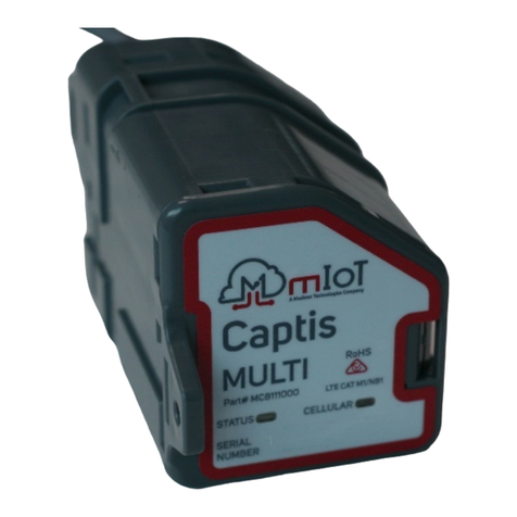
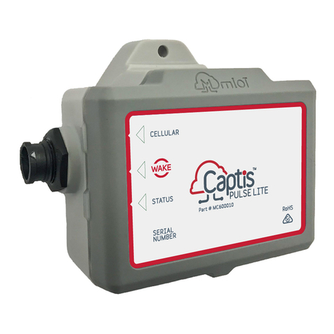
mIoT Captis Pulse Lite User manual

Sewer Level Monitoring Installation
Guide
Version 2
1/09/2022

1 Associated Documents
Document Name
mIoT - Captis Multi Installation Guide
mIoT - Captis Pulse Lite Installation Guide
2 Background
The Captis Pulse Lite1is a fit for purpose IoT device which can be used to effectively and
pro-actively monitor sewer level rises and as a result trigger alarm-based workflows. Captis
has been used for this purpose with large water authorities around the country for over 3
years.
The purpose of this document is to detail the installation guidelines of this solution in
conjunction with the Captis device, float switch/s and an external antenna.
Figure 1: Captis Pulse Lite
3 Safety
Installers must adhere to all workplace health and safety requirements and ensure they
receive all appropriate training and permits required to undertake this work.
mIoT, the device manufacturer takes no responsibility for the works undertaken and any
injury or damages that occur while installing Captis devices.
4 Installation Guide
This section aims to outline the basic steps of appropriately installing a Captis device to
monitor sewer risers. These guidelines have been provided based on extensive experience
from water authorities and deviating from these guidelines may result in a sub-optimal
deployment
4.1 Tools & Equipment
This subsection aims to outline the tools required but this is ultimately at the installer’s
discretion:
● Hammer Drill | Chisel bit, 8mm x 500mm masonry bit
● Screwdriver
1The Captis Pulse Lite shall be an external antenna variant and paired with an appropriate antenna.
Sewer Level Monitoring Installation Guide
Page | 1

● Hammer
● Cable ties
● Strain relieving thimble
● Eyebolt
4.2 Site
Ensure that you appropriately identify the site of install and notify or receive approval from
the appropriate government bodies or landholders to undertake these works.
4.3 Work Instructions
These work instructions act as a basic guide to instruct the installer of the best practice
workflow. It is understood that the installer may deviate from these guidelines based on the
environmental factors at the time. The integrity of the device and float switch shall be
prioritised when deviating from the following guide.
4.3.1 Step 1 - Drilling
The installer will need to drill a hole in the inside wall of the riser to mount an eyebolt.
Figure 2: Reference for hole location
● Open the Manhole (MH) and gas test
● Drill an 8mm hole in solid concrete/brick at a minimum of 100mm from the
base of the MH rim. The location of the 8mm hole will be determined by
several factors:
oUpstream side of the MH to prevent the float being pulled
downstream during surcharge, if possible.
oNot in front of a drop-junction or overflow window as this will cause
the float to be damaged and potential fouling to occur leading to the
alarm being triggered
Sewer Level Monitoring Installation Guide
Page | 2

oNot be directly adjacent to the step irons as this can lead to the float
becoming tangled and stuck in the ‘alarm’ position during internal
surcharge events.
Sewer Level Monitoring Installation Guide
Page | 3

● Insert an eyebolt into the hole and screw it in the rest of the way using a
screwdriver. Best practise is to rotate the eyebolt until tight but also with the
eye piece in the horizontal position to allow for ease of attachment of the
thimble and device. If required, a hammer can be used to begin to insert the
eyebolt and enable the thread to catch once it is turned with the screwdriver.
Figure 3: Reference for Eyebolt
● Using the long 500mm drill bit, drill through the road into the MH. Once a
hole has been cleared, a small cavity, slightly larger than the antenna is
created using a chisel bit.
Figure 4: Reference for Antenna Hole
●
Sewer Level Monitoring Installation Guide
Page | 4

● Pull antenna lead through the hole and connect it to the device. The antenna
should sit snuggly in the cavity with enough room to cover with road base.
Figure 5: Reference for Antenna channel
● Cover the antenna and remaining cavity with road base. Using a mallet,
compact the road base and smoothen. The surface should be returned to
the original condition.
oSweep up any remaining debris.
Figure 6: Reference for Antenna (finished)
4.3.2
Sewer Level Monitoring Installation Guide
Page | 5

4.3.3 Mounting Equipment
● Measure the MH depth with a tape measure, in line with the eyebolt, from
the MH rim to the invert of the pipe. Using the known pipe diameter,
calculate 100mm above the pipe inlet and determine which float switch will
be required for installation (e.g. 2m, 4m, 6m, 10m float lengths).
oNote: Conduct a test to determine whether the float has the potential
to become caught on benches, overflow windows and/or drop
junctions
● After confirming the length of float switch, wrap the chosen cable around a
thimble, and cable tie tightly to create an anchor point.
Figure 7: Reference for strain relief thimble
● Cable tie the float switch to the eyebolt using the thimble and loop any
excess lead. If the float switch is not at the right height, remove and redo.
Figure 8: Reference for float switch mounting
Sewer Level Monitoring Installation Guide
Page | 6

●
Sewer Level Monitoring Installation Guide
Page | 7

● Prior to placing the device into the MH, plug the float switch into the side of
the device. The connection point will click and lock.
● Use amalgamation tape to seal the connection point between the antenna
and the device and the float switch and the device.
● Reseal the antenna hole with silicon, mastic or clay and ensure the cable
and antenna are reburied.
● Use amalgamation tape to seal the connection point between the float and
the device.
● Note: Avoid placing weight on the anchor point as the spring system can
break under pressure. The device can then be secured to the eyebolt.
Figure 9: Reference for device mounting
4.3.4 Testing
Prior to completely closing the lid, flip the float switch multiple times and then wake the
device using the Use the magnet provided to ‘Wake’ the Captis device by holding it over the
below symbol.
The status light should flash, followed by a solid cellular light.
With the device installed, the antenna and float switch terminated, and the MH cover
replaced ensure that the device is connecting appropriately to the network. The functional
test outlined above should ensure that data is available in your platform.
If there are no signs of connectivity, please contact your support team.
Sewer Level Monitoring Installation Guide
Page | 8

● You can now reseal the MH and return it to its previous condition
Sewer Level Monitoring Installation Guide
Page | 9
Other manuals for Captis Pulse Lite
3
Table of contents
Other mIoT Measuring Instrument manuals
Popular Measuring Instrument manuals by other brands

Endress+Hauser
Endress+Hauser Levelflex FMP51 Safety instruction

SoftdB
SoftdB Mezzo Sound Intensity Probe user guide

LaserLiner
LaserLiner LaserRange-Master Gi7 Pro operating instructions

Hanna Instruments
Hanna Instruments Foodcare HI981035 instruction manual

Zamel
Zamel LEM-30 instruction manual

Sper scientific
Sper scientific AquaShock 850046K user manual