Mira Vier User manual

1
1144486-W2-K
These instructions must be left with the user
Installation Guide
Mira Vier

2
1144486-W2-K
CONTENTS
Introduction................................................................................................3
Products Covered by this Guide...........................................................3
Guarantee ............................................................................................3
Patents and Design Registration..........................................................3
Important Safety Information .....................................................................4
Pack Contents ........................................................................................... 6
Specications ............................................................................................9
Standards and Approvals .....................................................................9
Dimensions.............................................................................................. 11
Installation ...............................................................................................12
General............................................................................................... 12
Important Information Regarding Radio Controlled Devices.............. 12
Installation Schematic ........................................................................ 18
Position and Signal Test .....................................................................20
Shower Fittings - Ceiling Fed .............................................................23
Shower Fittings - Rear Fed ................................................................26
Wireless Controller ............................................................................30
Commissioning........................................................................................31
Connecting a Second Wireless Controller............................................... 33
Re-Registering ........................................................................................34
Fault Diagnosis........................................................................................35
Maintenance............................................................................................43
Spare Parts ............................................................................................. 44
Disposal and Recycling ...........................................................................47
Customer Service.......................................................................Back Page
If you experience any difculty with the installation or operation
of your new shower, then please refer to the Fault Diagnosis section,
before contacting Kohler Mira Ltd.
Our telephone and fax numbers can be found in the back of this guide.

3
1144486-W2-K
Thank you for purchasing a quality Mira product. To enjoy the full potential of your
new product, please take time to read this guide thoroughly. Having done so, keep
it handy for future reference.
The Mira Vier Mixer Valve is designed to be used with the Mira Vier showerhead
and ttings.
Products Covered by this Guide
Mira Vier Digital Mixer - High Pressure/Combi Valve
Mira Vier Digital Mixer - Pumped Valve.
Mira Vier Wireless Controller.
Mira 360 Fittings (Ceiling Fed or Rear Fed).
Guarantee
For domestic installations, Mira Showers guarantee the Mira Vier against any defect
in materials or workmanship for a period of ve years from the date of purchase
(shower ttings for one year).
For non-domestic installations, Mira Showers guarantee the Mira Vier against any
defect in materials or workmanship for a period of one year from the date of purchase.
For terms and conditions refer to the back cover of this guide.
Recommended Usage
Domestic
Light Commercial
Heavy Commercial
Healthcare
Patents and Design Registration
Design Registration 001203301
Patents GB: 2 392 225, 2 421 297
USA: 7 240 850, 7 669 776
Patent Applications
UK:
0723827.2
Europe: 2 227 647
China: CN 101918743A
India: 1306/MUMNP/2010
USA: US-2010-0282326-A1
WO: 2009/022112, 2009/071902
INTRODUCTION

4
1144486-W2-K
IMPORTANT SAFETY INFORMATION
Warning!
Follow all warnings, cautions and instructions contained in this guide, and
on or inside the appliance.
1. THIS APPLIANCE MUST BE EARTHED. ENSURE SUPPLEMENTARY
BONDING COMPLIES WITH THE “REQUIREMENTS FOR ELECTRICAL
INSTALLATIONS”. The Mira Digital Mixer Valve is intended to be permanently
connected to the xed electrical wiring of the mains system. A means for electrical
isolation of the appliance shall be provided in the xed wiring in accordance with
local wiring regulations.
2. Products manufactured by us are safe and risk-free, provided that they are
installed, used and maintained in good working order, in accordance with our
instructions and recommendations.
3. Isolate the electrical and water supplies before connecting to the appliance.
4. This appliance must be provided with means for disconnection that is incorporated
into the xed wiring in accordance with the relevant local wiring regulations.
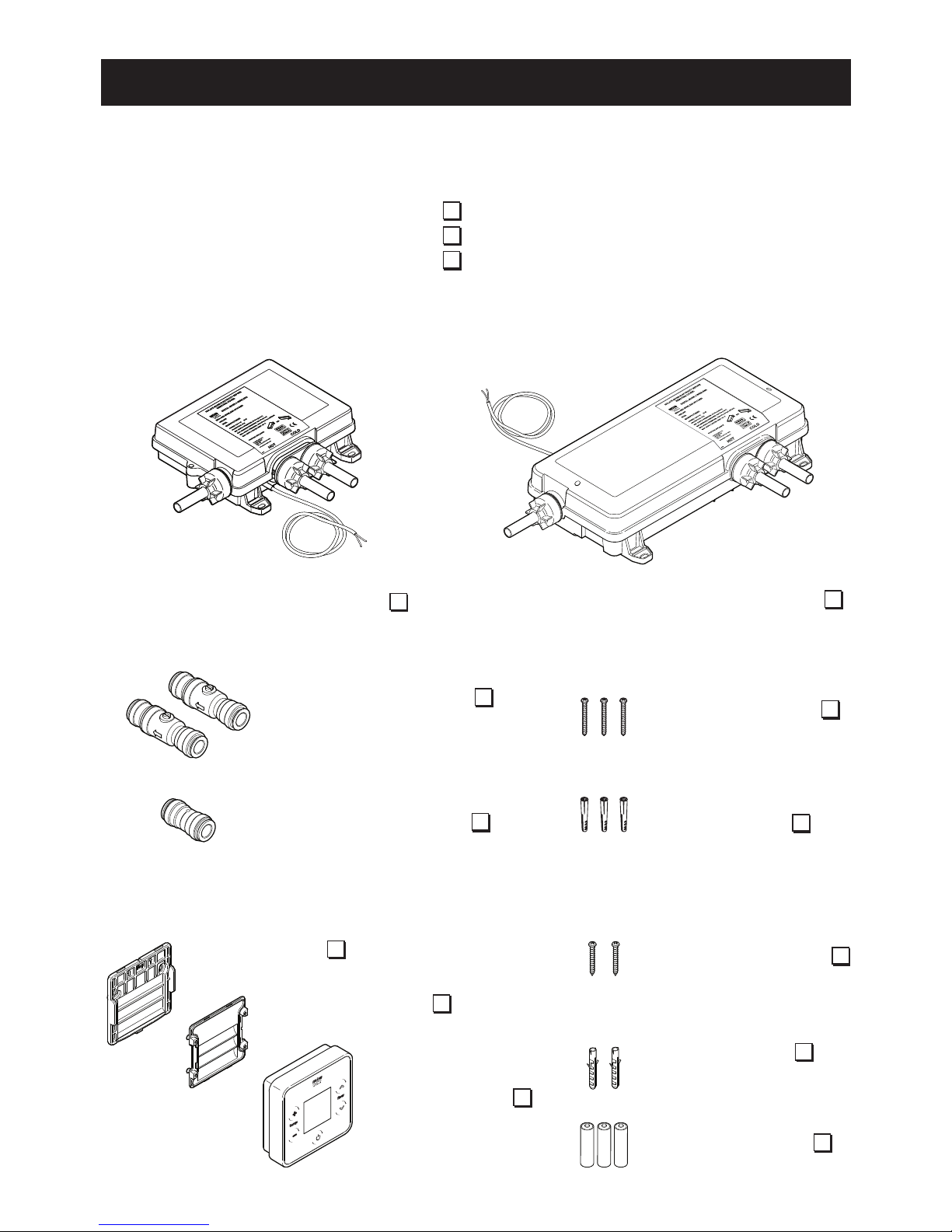
5. Refer to the wiring diagram before making any electrical connections.
6. Mains connections are exposed when the cover of the Digital Mixer Valve is
removed.
7. The Digital Mixer Valve must not be installed where it can become frozen.
8. Make sure that any pipework that could become frozen is properly insulated.
9. In accordance with BS7671 a 30mA Residual Current Device (RCD) should
be included in the electrical circuit. This may be part of the consumer unit or a
separate unit.
10. All pipework must be checked for leaks before the product installation is
completed. The product should be pressurised and both inlet & outlet connections
inspected.
11. If the shower is dismantled during installation or servicing then upon completion
the product must be inspected to ensure all electrical connections are tight and
that there are no leaks.
12. Having completed the installation, make sure that the user is familiar with the
operation of the appliance.
13. DO NOT commission this appliance if water leaks from the unit.
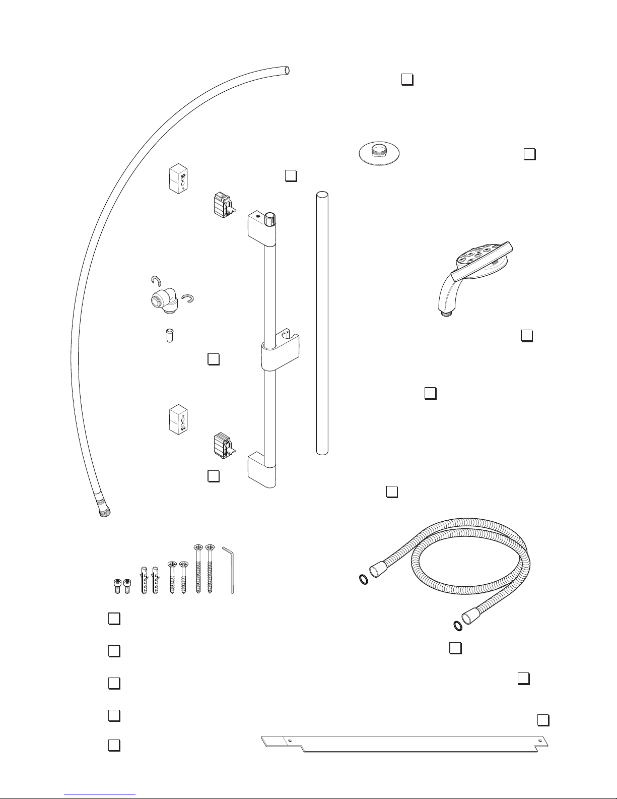
14. Only Mira recommended outlet ttings should be used.
15. Ensure all electrical connections are tight, to prevent overheating.
16. This product is not suitable for areas with high humidity (i.e steam rooms).
Please consult your installer.
17. The water supplies to this product must be isolated if the product is not to be
used for a long period of time. If the product or pipework is at risk of freezing
during this period they should also be drained of water.

5
1144486-W2-K
Caution!
1. Read all of these instructions and retain this guide for later use.
2. The electrical installation must comply to “BS 7671 - Requirements for Electrical
Installations” commonly referred to as the IEE Wiring Regulations, or any
particular regulations and practices, specied by the local electricity supply
company.
3. The plumbing installation must comply with the requirements of UK Water
Regulations / By-laws (Scotland), Building Regulations or any particular
regulations and practices, specied by the local water company or water
undertakers.
4. Make sure that you fully understand how to operate this shower and make sure
that it is properly maintained in accordance with the instructions given in this
manual.
5. Children should be supervised to make sure that they do not play with the
appliance.
6. Anyone who may have difculty understanding or operating the controls of the
shower should be supervised whilst showering.
Particular consideration should be given to:
• The young
• The elderly
• The inrm
• The disabled
• Anyone who suffers from a medical condition that can result in
temporary incapacity (e.g. Epilepsy or blackouts).
• Anyone inexperienced in the correct operation of the controls.
7. The appliance is not intended for use by persons (including children) with reduced
physical, sensory or mental capabilities, unless they are supervised or have been
given instruction concerning the use of the appliance by a person responsible
for their safety. Sunburn or skin conditions can increase your sensitivity to hot
water. Make sure that you set the shower to a cooler temperature.
8. If any of the following conditions occur, isolate the electricity and water supplies
and refer to section “To contact us”, in the back cover of this guide.
• If the cover is not correctly tted and water has entered the appliance case.
• If the case is damaged.
• If the appliance begins to make an odd noise, smell or smoke.
• If the appliance shows signs of a distinct change in performance, indicating
a need for maintenance.
9. DO NOT operate if water leaks from the appliance.
10. DO NOT operate this appliance if it is frozen. If suspected of being frozen, isolate
and contact us for advice.

6
1144486-W2-K
PACK CONTENTS
Wireless Controller
OR
Tick the appropriate boxes to familiarise yourself with the part names and to conrm
that the parts are included.
Documentation
1 x Wireless Controller User Guide
1 x Showerhead User Guide
1 x Customer Support Brochure
Digital Mixer Valve
1 x Wireless
Controller
1 x Backplate
1 x Battery Cover
2 x Fixing Screws
2 x Wall Plugs
3 x AA Batteries
3 x Fixing Screws
2 x Push-Fit Isolators
3 x Wall Plugs
1 x Outlet Connector
Digital Mixer -
High Pressure/Combi Valve Digital Mixer - Pumped Valve

7
1144486-W2-K
Ceiling Fed Fittings
1 x Installation Template
1 x Ceiling Plate
1 x Showerhead
1 x Extension
1 x Slide Bar
Assembly
2 x Brackets
2 x Hex Screws
2 x Wall Plugs
2 x 45mm Screws
2 x 70mm Screws
1 x Hex Key
1 x Elbow Kit
2 x Spacers
2 x Rubber Washers
1 x Hose
1 x Plastic Pipe

8
1144486-W2-K
Rear Fed Fittings
2 x Hex Screws
2 x Wall Plugs
2 x 45mm Screws
1 x Hex Key
1 x Installation Template
2 x Rubber Washers
1 x Right Angle
Connector (RAC) Kit
1 x Right Angle
Connector Shroud
1 x Hose
2 x Brackets
1 x Slide Bar
Assembly
2 x End Plugs
1 x Showerhead

9
1144486-W2-K
SPECIFICATIONS
Standards and Approvals
The Mira Vier complies with all relevant directives for CE marking. The Mira Vier is
a type 1 electronic, independently mounted control for surface mounting.
The Mira Vier is in compliance with the essential requirements of the R&TTE directive
1999/5/EC. A copy of the declaration of conformity may be obtained by contacting
Kohler Mira Limited, U.K customer services department.
General
Pollution Degree 2
Rated Impulse Voltage 2.5 kV
Suitable for Drinking Not Suitable
Connections 15 mm Compression/Pusht
Mira Digital Mixer Valve High Pressure (Not suitable for Pumped
Gravity Systems)
Pressures
Maximum Static Pressure 1000 kPa (10 bar) = 100 m max. total head
Maximum Maintained Pressure 500 kPa (5 bar) = 50 m max. total head
Minimum Maintained Pressure 50 kPa (0.5 bar) = 5 m max. total head
Supply Pressure Differential Nominally Equal
Temperatures
Maximum Temperature (factory preset) 45 °C
Maximum Temperature (setting range) 35 °C - 48 °C
Minimum Temperature Thermostatic control down to 30 °C
Hot Water Range 55 °C - 65 °C
Cold Water Range 1 °C - 20 °C
Temperature Stability ± 1 °C at recommended supply conditions
Ambient Temperature 1 °C - 40 °C
Maximum Relative Humidity 95% non-condensing
Flow Rates and Times
Nominal Flow Rates (will vary depending
on inlet maintained pressure and spray
mode)
Max @ 1.0 bar = 16l/min
Min @ 1.0 bar = 5l/min
Electrical
Supply Voltage 230V AC 50 Hz
Maximum Load 20 W

10
1144486-W2-K
Mira Digital Mixer Valve Pumped
Pressures
Maximum Static Pressure 100 kPa (1 bar) = 10 m max. total head
Maximum Maintained Pressure 100 kPa (1 bar) = 10 m max. total head
Minimum Maintained Pressure 1 kPa (0.01 bar) = 0.1 m min. total head
Supply Pressure Differential Nominally Equal
Temperatures
Maximum Temperature (factory preset) 45 °C
Maximum Temperature (settable range) 39 °C - 48 °C
Minimum Temperature Thermostatic control down to 30 °C
Full Cold also selectable
Hot Water Range 50°C - 65°C
Cold Water Range 1°C - 20°C
Temperature Stability ± 1°C at recommended supply conditions
Ambient Temperature 1°C - 40°C
Maximum Relative Humidity 95% non-condensing at 30 °C
Flow Rates and Times
Flow Rates (will vary depending on inlet
maintained pressure and spray mode)
Max @ 0.01 bar = 16 l/min
Min @ 0.01 bar = 6 l/min
Electrical
Supply Voltage 230V AC 50 Hz
Maximum Load 200 W at 230V AC

11
1144486-W2-K
DIMENSIONS
FOR LOW PRESSURE SYSTEMS
PARTNo. 1666.007
N85B
MANUFACTUREDDATE:
KOHLERMIRA LTD.
CHELTENHAM
GL525EP
TEL:(+44) 0870 241 0888
www.mirashowers.co.uk
POWER:230V ~ 200W
PROTECTION:IP24
MIN.SUPPLY HEAD: 0.1 m (0.01 bar)
MAX.WORKING HEAD: 10 m (1 bar)
MAX.SUPPLY WATER TEMP: 65 °C
MOUNTINGPOSITION
VERTICAL HORIZONTAL
OR
ISOLATEMAINS ELECTRICITY BEFORE
REMOVING COVER!
F8625
PLATINUMDIGITAL MIXER
HOT COLD
FOR HIGH PRESSURE / COMBINATIONBOILER
PARTNo. 1666.009
N85A
MANUFACTUREDDATE:
KOHLERMIRA LTD.
CHELTENHAM
GL525EP
TEL:(+44) 0870 241 0888
www.mirashowers.co.uk
HOT COLD
POWER:230V ~ 20W
PROTECTION:IP24
MIN.SUPPLY PRESSURE: 50 kPa (0.5 bar)
MAX.WORKING PRESSURE: 500 kPa (5 bar)
MAX.STATIC PRESSURE: 1000 kPa (10 bar) (WRAS)
MAX.SUPPLY WATER TEMP: 65 °C
MOUNTINGPOSITION
VERTICAL HORIZONTAL
OR
ISOLATEMAINS ELECTRICITY BEFORE
REMOVING COVER!
F8624
PLATINUMDIGITAL MIXER
68 mm 240 mm
180 mm
180 mm
185 mm
127 mm
255 mm
35 mm
217 mm
36 mm
36 mm 394 mm
315 mm
45 mm
86 mm
47 mm
47 mm
to centre of inlets/outlet
to centre of outlet
to centre of inlets
600 mm
650 mm
150 mm
62 mm
82 mm
645 mm
Max. to ceiling

12
1144486-W2-K
INSTALLATION
General
The installation must be carried out in accordance with these instructions, and must
be conducted by designated, qualied and competent personnel.
The Digital Mixer Valve may be installed in a loft space, under the bath or in a
convenient cupboard space provided there is enough room for maintenance
(e.g. Removal of Digital Mixer Valve lid). Failure to do so may result in an
inability to carry out any maintenance. Safe and easy access to the product
should be available at all times.
When installing a mixer valve in an area not regularly accessed, consideration
for potential leaks must be taken into account. While such events are unlikely,
it is advisable to periodically check the installation for traces of water on or
around the product. If possible, site the valve in a location where any leak
would be contained or routed to avoid areas sensitive to water damage.
Isolating valves must be installed to both inlets (supplied) and outlet, close to the
Digital Mixer Valve for ease of maintenance.
Caution! Risk of product damage. The Digital Mixer Valve must be installed in
a dry, ventilated area where it will not freeze.
Important Information Regarding Radio Controlled Devices
• Metal objects such as steel baths or sinks, cold water storage tanks, hot water
cylinders, foil lined plaster board walls, radiators and even thick brick walls, can
all dramatically reduce the radio operational range of any radio controlled product.
• Interference from other radio signals can dramatically reduce the ability of the
Vier Wireless Controller / digital mixer to register or communicate. This may
include; mobile phones, radio control boiler thermostats, wireless broadband
routers, radio control toys, cordless phones, remote outdoor weather stations,
wireless doorbells etc.
• If you encounter difculty registering the wireless controller and digital mixer
ensure all other radio interference is temporarily switched off.
Note! Failure to follow these guidelines can result in poor, intermittent or complete
failure to communicate with the digital mixer.
Note! Both the Wireless Controller and Digital Mixer contain internal radio
transmission aerials which are directional in operation. In order to achieve optimum
radio signal strength and therefore optimum communication distance It may be
necessary to alter the Wireless Controller and Digital Mixer relative orientation /
position to each other.

13
1144486-W2-K
MIRADM2 WIRELESS
HP/COMBI
1666.009
N85A
MANUFACTURED
KOHLERMIRALTD.
CHELTENHAM
GL525EP
TEL:(+44)0870 241 0888
www.mirashowers.com
HOT COLD
POWER:230 V AC 20W
PROTECTION:IP24
MIN.SUPPLYPRESSURE: 50 kPa (0.5 bar)
MAX.WORKING PRESSURE: 500 kPa (5 bar)
MAX.STATICPRESSURE: 1000 kPa (10 bar) (WRAS)
MAX.SUPPLYWATER TEMP: 65 °C
POSITIONAPPLIANCE OR
ISOLATEMAINS ELECTRICITY BEFORE
REMOVINGCOVER!
F9001
DIGITALMIXER 2 WIRELESS
cold
warm
hot
Only install the High Pressure Digital Mixer Valve with a multipoint gas water heater
or combination boiler of a fully modulating design (i.e. where the water draw-off
rate indirectly controls the gas ow rate to the burner).
An expansion vessel must be tted (and regularly maintained) if any form of backow
prevention device is tted, e.g. Non-return valve or PRV. This will ensure that excess
expansion or pulse pressures do not damage the product or plumbing system. The
expansion vessel may already be tted within the boiler (check with the manufacturer)
and is in addition to the normally larger central heating expansion vessel.
Typical Suitable Installations:
Mira Vier
Shower Fittings
Digital Mixer
Valve (HP)
Float Valve
Key to Symbols
Isolating Valve
Tempering Valve
Overow Indicator
Mini Expansion Vessel
Pressure Reducing
Valve
COLD HOT
Combination
Boiler
1. Instantaneous Multipoint Water Heaters and Combination Boilers
Caution! Risk of product damage. Do not t the Mira Digital Mixer - PUMPED
VALVE with Instantaneous Multipoint Water Heaters or Combination Boilers.

14
1144486-W2-K
Use of Flow Regulators with Combination Boilers
The Mira Digital Mixer Valve can demand hot water quicker than some instantaneous
water heaters/combination boilers can provide, especially in winter when the mains
water is colder. A Hot inlet ow regulator may need to be used to ensure that the
Digital Mixer Valve can deliver a full range of water temperatures.
Note:
The Mira Single outlet digital mixing valves are factory tted with an 8 l/min hot
inlet ow regulator. If installing a single outlet digital mixer with a combi boiler rated
36kW or greater or to mains pressurised systems the hot inlet ow regulator should
be removed.
Note:
The Mira Dual outlet digital mixing valves do not have a factory tted hot inlet ow
regulator. These are supplied in the component pack. The table indicates which
ow regulator should be tted in the hot water inlet of the Mira Digital Mixer Valve if
installing to a combination boiler system.
Unscrew hot inlet plastic nuts and remove pipe and seal to gain access to the
checkvalve cartridge and lter.
Use at blade screwdriver to carefully lever cartridge out.
Fit/remove the ow regulator from checkvalve cartridge behind lter as required.
Ret seal, pipe and plastic nut. Plastic nuts require hand tightening only.
Green
Orange
Dual outlet valve shown
Boiler Rating 24 kW (80,000 Btu/h) 30 kW (100,000 Btu/h) 36 kW (120,000 Btu/h)
Flow Regulator 7 litres/min 9 litres/min Not required
Colour White/Green White/Orange -

15
1144486-W2-K
MIRADM2WIRELESS
HP/COMBI
1666.009
N85A
MANUFACTURED
KOHLERMIRALTD.
CHELTENHAM
GL525EP
TEL:(+44)0870241 0888
www.mirashowers.com
HOT COLD
POWER:230V AC 20W
PROTECTION:IP24
MIN.SUPPLYPRESSURE: 50 kPa (0.5 bar)
MAX.WORKINGPRESSURE: 500 kPa (5 bar)
MAX.STATICPRESSURE:1000 kPa (10 bar) (WRAS)
MAX.SUPPLYWATERTEMP: 65 °C
POSITIONAPPLIANCE OR
ISOLATEMAINSELECTRICITY BEFORE
REMOVINGCOVER!
F9001
DIGITALMIXER2 WIRELESS
cold
warm
hot
Digital Mixer
Valve (HP)
COLD
HOT
Mira Vier
Shower Fittings
2. Mains Pressurised Instantaneous Hot Water Shower, Heated from
a Thermal Store
Caution! Risk of product damage. Do not t the Mira Digital Mixer - PUMPED
VALVE with Mains Pressurised Systems.
Use of Warm-up Feature with Combination Boilers
When using the warm-up feature (see User Guide) with the digital mixer valve supplied
via an instantaneous water heater/combination boiler, the user may experience a
brief temperature uctuation. This is caused by the normal operation of a standard
instantaneous water heater/combination boiler whereby the boiler will turn off when
the ow is stopped (as happens after the warm-up sequence has been completed).
Upon restart of the shower, a cold shot will be ushed through followed by a brief
hot shot until the hot water supply has stabilised.
Packages of this type, tted with a tempering valve can be used. A drop type pressure
reducing valve must be tted (and regularly maintained) if any form of backow
prevention device is tted, e.g. non-return valve, PRV, then an expansion vessel
should also be tted. This will ensure that excess expansion or pulse pressures do
not damage the product or the plumbing system. The expansion vessel may already
be tted externally or internally within the thermal store (check with thermal store
manufacturer).

16
1144486-W2-K
Mira Vier
Shower Fittings
MIRADM2WIRELESS
HP/COMBI
1666.009
N85A
MANUFACTURED
KOHLERMIRALTD.
CHELTENHAM
GL525EP
TEL:(+44)0870241 0888
www.mirashowers.com
HOT COLD
POWER:230V AC 20W
PROTECTION:IP24
MIN.SUPPLYPRESSURE: 50 kPa (0.5 bar)
MAX.WORKINGPRESSURE: 500 kPa (5 bar)
MAX.STATICPRESSURE:1000 kPa (10 bar) (WRAS)
MAX.SUPPLYWATERTEMP: 65 °C
POSITIONAPPLIANCE OR
ISOLATEMAINSELECTRICITY BEFORE
REMOVINGCOVER!
F9001
DIGITALMIXER2 WIRELESS
cold
coldcold
warm
hot
hot
MIRADM2WIRELESS
HP/COMBI
1666.009
N85A
MANUFACTURED
KOHLERMIRALTD.
CHELTENHAM
GL525EP
TEL:(+44)0870241 0888
www.mirashowers.com
HOT COLD
POWER:230V AC 20W
PROTECTION:IP24
MIN.SUPPLYPRESSURE: 50 kPa (0.5 bar)
MAX.WORKINGPRESSURE: 500 kPa (5 bar)
MAX.STATICPRESSURE:1000 kPa (10 bar) (WRAS)
MAX.SUPPLYWATERTEMP: 65 °C
POSITIONAPPLIANCE OR
ISOLATEMAINSELECTRICITY BEFORE
REMOVINGCOVER!
F9001
DIGITALMIXER2 WIRELESS
1.0 metre
minimum
100 mm from the lowest level of
water in the tank
Cistern
Minimum 230 litres
90°
30° - 60°
Air Separation
3. Gravity Fed Showers
Caution! Risk of product damage. Do not t the Mira Digital Mixer - HIGH
PRESSURE/COMBI VALVE with Gravity Fed Systems.
Digital Mixer
Valve (Pumped)
The shower control must be fed from a cold water storage cistern and a hot water
cylinder providing nominally equal pressures. Pipework layouts and connections
must be such that other draw-offs will not effect water supplies to the shower, shared
supplies may lead to airlocking or water starvation. It is therefore best practice to have
independent hot and cold supplies to the Low Pressure (pumped) Digital Mixer Valve.

17
1144486-W2-K
Typical Examples of Poor Plumbing and Installation Practices
DO NOT:
• Install the Digital Mixer Valve where it can become frozen
• Install the Digital Mixer Valve where it can be subjected to ambient tempera-
tures in excess of 40ºC
• Position the Digital Mixer Valve where maintenance access is poor or unsafe
• Install into a system where the cold water cistern holds less than 230 litres
• Install into a system where air locking could occur
• Install the wireless controller in a position where communication with the
Digital Mixer Valve is poor e.g. mixer valve installed under metal bath, in front
of metal cistern, on foil backed plasterboard, more than the recommended
distance away etc.
• Install the Digital Mixer Valve onto shared water supplies
• Install the Digital Mixer Valve less than 100 mm from the lowest level of water
in the cistern (low pressure version only)
• Fit plastic pipework unless rigidly supported
• Install a High Pressure/Combi Valve to a Pumped Gravity System
Shower Installation
Bath Installation
Affected by Metal
Bath / Poor or no
Communication
Shared
Supplies
No
Access
Steel / Cast
Bath
Less than
230 Litres
Incorrect
Cold
Take-off
Incorrect
Hot
Take-off
Air-locking
Pipework
Distance Too Far /
Poor or No
Communication
Less than
230 Litres
Incorrect
Cold
Take-off
Incorrect
Hot
Take-off
Plastic pipework
not rigidly
supported.

18
1144486-W2-K
Mira Vier Shower
Fittings & Wireless Controller
Installation Schematic
Isolators
Isolator
Outlet
Metal pipework must be
earth bonded
To Mains
Power Supply
Hot Inlet
A separate, permanently connected supply must be taken from the ring main
to the appliance through a 3 amp double pole switched fuse spur providing a
minimum 3mm contact separation gap in each pole.
Ensure the switched fused spur is easily accessible for servicable and resetting
purposes.
The use of supply-line or zone strainers will reduce the need to remove debris
at the Digital Mixer Valve. The recommended maximum mesh aperture
dimension for such strainers is 0.5 mm.
Pipework must be rigidly supported to avoid any strain on the connections.
A 30 mA Residual Current Device (RCD) must be included in the electrical
circuit. This may be part of the consumer unit or a separate unit.
3 amp switched
fused spur.
Easily Accessible
Cold Inlet
Digital Mixer
Valve

19
1144486-W2-K
Mounting on a Vertical Surface
Inlets
Outlet
Inlets
Outlet
Mounting on a Horizontal Surface
Long inlet pipework (dead-legs) should be kept to a minimum to avoid temperature
uctuations.
Supply pipework layout must be arranged to minimize the effect of other outlet
usage upon the dynamic pressures at the Digital Mixer Valve inlets.
To eliminate pipe debris it is essential that supply pipes are thoroughly ushed
through before connection to the Digital Mixer Valve.
The Digital Mixer Valve (which contains the thermostatic mixing valve) may
only be orientated in the positions shown above when mounted on a vertical
or horizontal surface. Failure to do so will compromise the ability of the unit to
fail-safe and deliver constant blend.
If the power supply cable is damaged, it must be replaced by the manufacturer
or a service engineer.
Warning! Turn off the electrical and water supplies before proceeding with
the installation of the appliance. The electricity must be turned off at the
mains and the appropriate circuit fuse electrically isolated, if applicable.
Valve Installation Orientation

20
1144486-W2-K
MIRADM2 WIRELESS
HP/COMBI
1666.009
N85A
MANUFACTURED
KOHLERMIRA LTD.
CHELTENHAM
GL525EP
TEL:(+44) 0870 241 0888
www.mirashowers.com
HOTCOLD
POWER:230 V AC 20 W
PROTECTION:IP24
MIN.SUPPLY PRESSURE: 50 kPa (0.5 bar)
MAX.WORKING PRESSURE: 500 kPa (5 bar)
MAX.STATIC PRESSURE: 1000 kPa (10 bar) (WRAS)
MAX.SUPPLY WATER TEMP: 65 °C
POSITIONAPPLIANCEOR
ISOLATEMAINS ELECTRICITY BEFORE
REMOVING COVER!
F9001
DIGITAL MIXER 2 WIRELESS
Ceiling Fed
Fitting
Rear Fed
Fitting
Cold Water Inlet
Hot Water Inlet
Valve
Outlet
Wireless
Controller
10 m
(Free air)
Digital Mixer Valve
Position and Signal Test
3 amp switched
fused spur.
Easily accesible
Important! When choosing a position for the Digital Mixer Valve in relation to the
Wireless Controller and the Shower Fittings, consider the following points:
The Wireless Controller can be sited up to 10 m (free air) from the Digital Mixer
Valve. However, wall thicknesses and construction types may affect the remote
signal strength and thereby reduce the range. The Controller range should be
tested on site prior to installation to ensure shower’s reliability.
Refer to Section -INSTALLATION “Important Information Regarding Radio
Controlled Devices”.
Note! Both the Wireless Controller and Digital Mixer contain internal radio
transmission aerials which are directional in operation. In order to achieve
optimum radio signal strength and therefore optimum communication distance
It may be necessary to alter the Wireless Controller and Digital Mixer relative
orientation /position to each other.
The length of pipework running from the Digital Mixer Valve to the Shower Fitting
will have an effect on the showering temperature and the response time when
changing the temperature using the Wireless Controller. The shorter the length
of pipework from the Digital Mixer Valve the better the shower will respond. It
is recommended that this length does not exceed 5m from the valve outlet to
shower tting.
Other manuals for Vier
2
Table of contents
Popular Bathroom Aid manuals by other brands

EZee Life
EZee Life CH2035 quick start guide

Care & Independence
Care & Independence COMFORT VALUE CVT user guide

Mobilex
Mobilex 302066 user manual

NRS Healthcare
NRS Healthcare P23099 User instructions

Invacare
Invacare H450 operating instructions

Greentouch
Greentouch 2014ATH-113 Installation and care guide