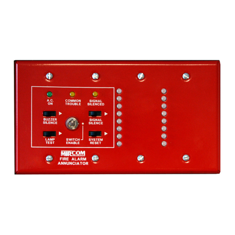
Mircom TX3 Series User manual
Other Mircom Intercom System manuals
Mircom
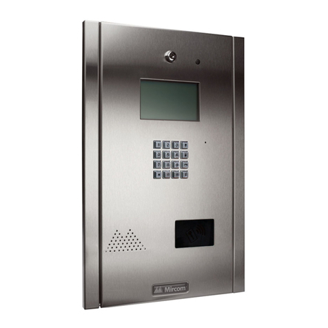
Mircom TX3 Series Owner's manual
Mircom
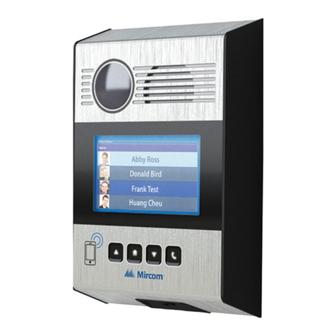
Mircom TX3 Nano User manual
Mircom
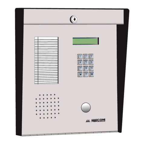
Mircom ADC Series Operating instructions
Mircom
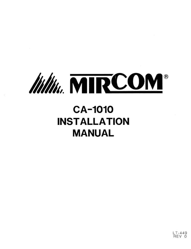
Mircom CA-1010 User manual

Mircom
Mircom CA-1010 User manual
Mircom
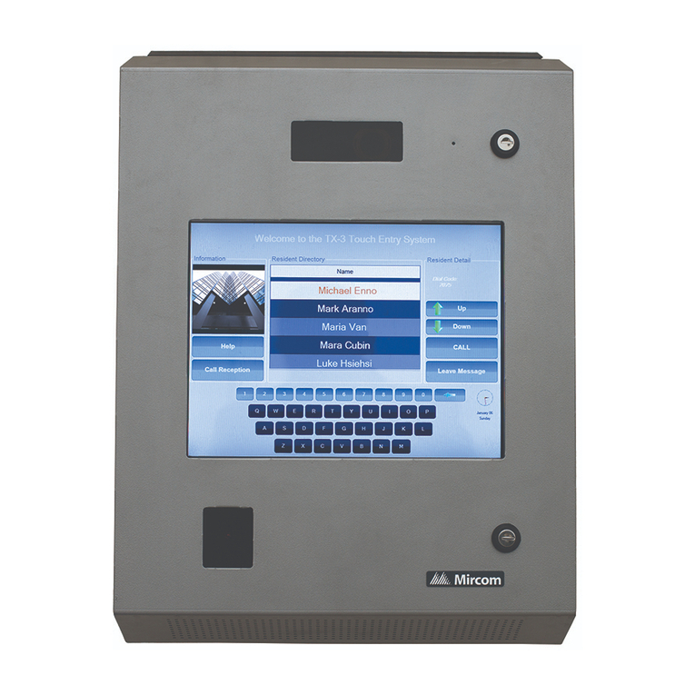
Mircom TX3-TOUCH-S15B-WR User manual
Mircom
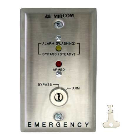
Mircom DA-100 User manual

Mircom
Mircom TX3 Series User manual
Mircom
Mircom EP-1000 User manual

Mircom
Mircom TX3 Series User manual
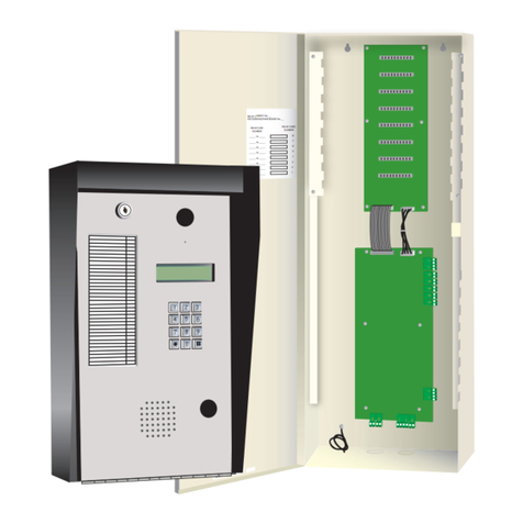
Mircom
Mircom TAS-2000 Series User manual
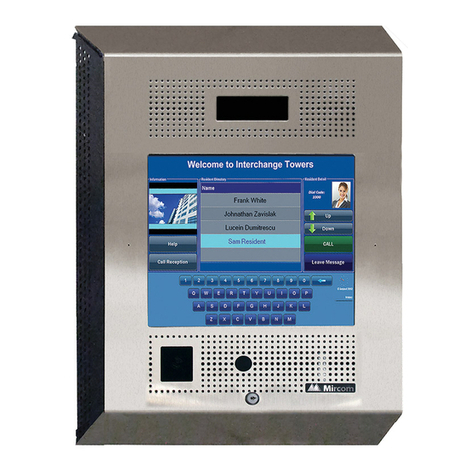
Mircom
Mircom TX3-TOUCH-F15-B User manual
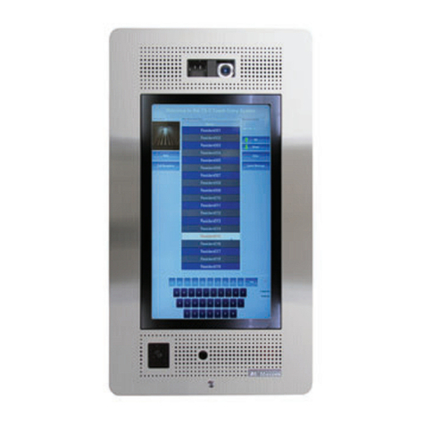
Mircom
Mircom TX3-TOUCH-UPS-KIT User manual
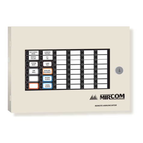
Mircom
Mircom RA-1000 Series User manual
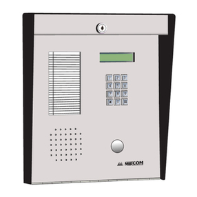
Mircom
Mircom 9500 Series Operating instructions

Mircom
Mircom TX3 Series Instruction sheet

Mircom
Mircom TX3 Series User manual
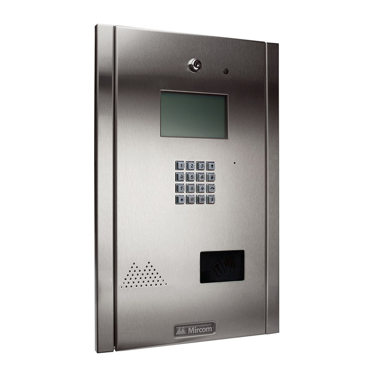
Mircom
Mircom TX3 Series User manual

Mircom
Mircom TX3 Series User manual
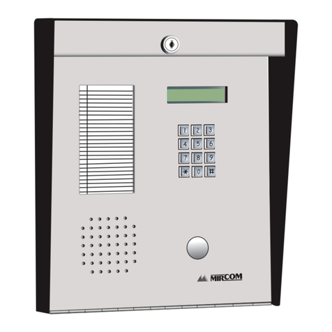
Mircom
Mircom Autodialer ADC Series User manual
Popular Intercom System manuals by other brands

MGL Avionics
MGL Avionics V16 manual

SSS Siedle
SSS Siedle BVI 750-0 Installation & programming

urmet domus
urmet domus AIKO 1716/1 quick start guide

urmet domus
urmet domus IPerVoice 1039 Installation

Alpha Communications
Alpha Communications STR QwikBus TT33-2 Installation, programming, and user's manual

Monacor
Monacor ICM-20H instruction manual

