Mirion Technologies WRM2 User manual

OPERATING MANUAL
WRM2
Wireless Remote Monitoring System 2
iPAM-Tx - Base transceiver - MESH Repeater - External Transceiver – RAMSYS-TRX - iMUX
- iMUX Area Monitor - Dive Repeater
Document # 15-00043
Revision 13
February 2012

15-00043
Revision 13
February 2012
All of the information in this document is the exclusive property of Mirion Technologies (MGPI), Inc. and is not to be disclosed, reproduced, or used except as 2
authorized in writing by Mirion Technologies (MGPI), Inc.
Revision Log
Revision # Date Revised
Pages Comments
0
1
2
3
4
5
6
7
8
9
10
07/31/2004
12/29/04
6/2005
9/2005
9/2006
3/2007
10/2008
06/13/2009
08/6/2009
02/090/2010
04/16/2010
N/A
ALL
ALL
13-14
26
ALL
ALL
27
28-30
31-32
33-28
Page 8
Pages 12
and 42
Pages 13,
15, and 18
Page 3
ALL
Original issue.
Added comments from KS/JK
- Update, add Images
- Modify Section 2.2.3, Radio Mode Selector
positions and description
- Minor reformatting
- Add Appendix 2: Alternate network Adapter
Programming
Section 2.2.3 Radio & Network Adapter Configuration:
- Modify Table 2 for description of Communication
Mode Summary
- Modify Figure 4 – Front Panel
Changes made to reflect actual operation of rotary
switch mode positions and description for WRM2 Base
Transceiver
Modify Table 3 to include baud rate settings for
devices connected to the WRM2 External Transceiver
General edits
General edits
Equipment to EXT Radio settings
iMUX Description
Dive MESH Repeater Description
Component Specifications
Removed “Only One MESH Repeater within Range of
Base” and explain the algorithm in section 2.32.
Added a note about the 5111 firmware version for the
WRM2 radio 2.33 page 22
Added a CAUTION statement on the importance of
upgrading the WRM2 radios in the ‘5111’ version of the
radio firmware, page 5
Added RAMSYS transmitter and Technical
Characteristics, sections 2.7 and 3.7. Added newer
logo.
Removed note containing “external power can be used
to power dosimeter when in PAM-TRX”
Added iPAM-TX transmitter and IMUX Area Monitor
with technical characteristics sections
Added statement: AA battery needs to be removed
when using an external power supplies for the iPAM-
TX
Added Hardware Warning
Added information to associate sections regarding the
2.4 GHz DM radio and other edits.

15-00043
Revision 13
February 2012
All of the information in this document is the exclusive property of Mirion Technologies (MGPI), Inc. and is not to be disclosed, reproduced, or used except as 3
authorized in writing by Mirion Technologies (MGPI), Inc.
11
12
13
06/20/2011
8/30/2011
2/28/2012
38-41
Page 4, 9
and Section
3
All
7-8
8
7-13, 49
9-13
31
40
41-42
54-55
Added information on Passive and Active Underwater
Antennas
Added statement about optional 900 MHz frequency
changes (910.8 - 914.7 MHz). Removed statement
about PAM-TX programming connector.
Updated product names.
Added information on optional iPAM-Tx external
battery power.
Changed iPAM-Tx buzzer volume. Added dead battery
warning. Added average battery life and transmission
range.
Deleted PAM TRX information.
Added battery usage and replacement details.
Added iMUX’s average battery life and transmission
range. Added clarification regarding reset tool’s
redundancy for later iMUX firmware versions.
Added iMUX-AM’s average battery life and
transmission range.
Added correct pictures of Q-TEMP Tx
Added component part numbers.

15-00043
Revision 13
February 2012
All of the information in this document is the exclusive property of Mirion Technologies (MGPI), Inc. and is not to be disclosed, reproduced, or used except as 4
authorized in writing by Mirion Technologies (MGPI), Inc.
Hardware Warning
WARNING: No user-serviceable parts inside equipment.
WRM2 FCC Compliance
WARNING: This device complies with Part 15 of the FCC rules. Operation is
subject to the following conditions: (1) this device may not cause harmful
interference and (2) this device must accept any interference received, including
interference that may cause undesired operation.
Antenna Warning
WARNING: This device has been tested with Reverse Polarity SMA and MMCX
connectors with the antennas that are supplied with the equipment. When
integrated in the OEM product, these fixed antennas require installation preventing end
users from replacing them with non-approved antennas. Any antennas not supplied by
MGP Instruments must be tested to comply with FCC Section 15.203 for unique antenna
connectors and section 15 emissions.
FCC Qualifications
Important: The WRM2 radio modules have been certified by the FCC for integration into OEM
products without any further certifications (as per FCC section 2.1091). Changes
not expressly approved by Mirion Technologies (MGPI), Inc. could void the user’s
authority to operate this equipment.
Frequencies and spacing hops:
900 MHz FHSS
•First Frequency: 910.5 MHz
•Last Frequency: 917.7 MHz
•Frequency Spacing: 300 KHz
900 MHz FHSS (Optional)
•First Frequency: 910.8 MHz
•Last Frequency: 914.7 MHz
•Frequency Spacing: 300 KHz
2.4 GHz FHSS 25 channels:
•First Frequency: 2450.15 GHz
•Last Frequency: 2459.75 GHz
•Frequency Spacing: 400 KHz
2.4 GHz DM ISM Band:
•Regulatory Approvals: FCC (USA) FCC ID: OUR-XBEE/OUR-XBEEPRO, IC (Canada) IC:
4214A-XBEE or IC: 4214A-XBEEPRO, ETSI CE Power output: 10 dBm (Europe), C-TICK
(Australia)

15-00043
Revision 13
February 2012
All of the information in this document is the exclusive property of Mirion Technologies (MGPI), Inc. and is not to be disclosed, reproduced, or used except as 5
authorized in writing by Mirion Technologies (MGPI), Inc.
Table of Contents
1.Introduction........................................................................................................................7
2.Equipment Description & Operation................................................................................8
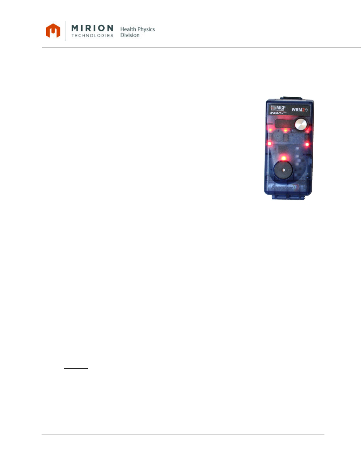
2.1.iPAM-Tx (Intelligent Personal Alarm Module Transmitter)...................................................8
2.1.1.Features:..............................................................................................................................8
2.1.2.Operation ...........................................................................................................................11
2.1.4.Operational Test ................................................................................................................12
2.1.5. Usage ................................................................................................................................13
2.1.6.Battery Replacement .........................................................................................................13
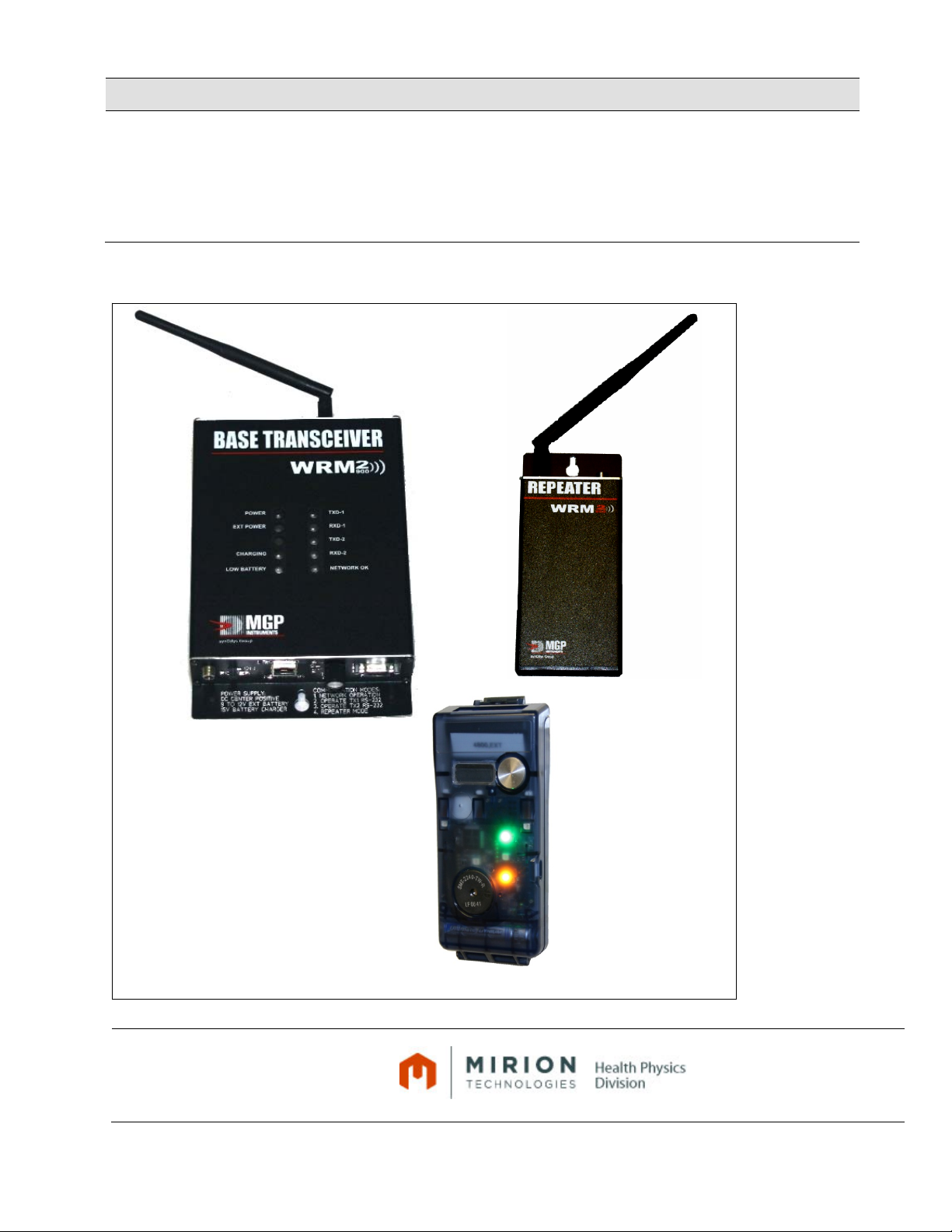
2.2.WRM2 Base Transceiver...................................................................................................13
2.2.1. Features:............................................................................................................................13
2.2.2. Operation ...........................................................................................................................15
2.2.3.Radio and Network Adaptor Configuration ........................................................................16
2.2.4. Batteries.............................................................................................................................22
2.2.5.Operational Test ................................................................................................................22
2.2.6. Usage ................................................................................................................................23
2.3.WRM2 MESH Repeater.....................................................................................................23
2.3.1. Features:............................................................................................................................23
2.3.2. Operation ...........................................................................................................................24
2.3.3. Settings..............................................................................................................................25
2.3.4.Operational Test ................................................................................................................25
2.3.5. Usage ................................................................................................................................25
2.3.6. Battery ...............................................................................................................................26
2.4.WRM2 External Transmitter ..............................................................................................26
2.4.1. Features.............................................................................................................................26
2.4.2. Operation ...........................................................................................................................27
2.4.3. Settings..............................................................................................................................28
2.4.4.Operational Test ................................................................................................................29
2.4.5. Usage ................................................................................................................................30
2.4.6. Battery ...............................................................................................................................30
2.4.7.Connection Cables used for the WRM2 External Transmitter. ..........................................30
2.5.WRM2 iMUX – Intelligent Multiplexer ................................................................................30
2.5.1. Features.............................................................................................................................30
2.5.2.Replacing Batteries............................................................................................................31
2.5.3.Operation Use....................................................................................................................32
2.5.4. Storage ..............................................................................................................................33
2.6.WRM2 Dive Repeater – Underwater Dive Antenna...........................................................33
2.6.1. Features.............................................................................................................................33
2.6.2. Operation ...........................................................................................................................34
2.7.WRM2 Active Dive Repeater – Active Dive Antenna.........................................................35
2.7.1. Features.............................................................................................................................35
2.7.2. Operation ...........................................................................................................................36
2.8.WRM2 RAMSYS TRANSMITTER .....................................................................................38
2.8.1. Features.............................................................................................................................38
2.8.2.Operation ...........................................................................................................................38
2.9.WRM2 iMUX AM – Intelligent Multiplexer Area Monitor ....................................................39
2.9.1. Features.............................................................................................................................39
2.9.2.Operation Use....................................................................................................................41

15-00043
Revision 13
February 2012
All of the information in this document is the exclusive property of Mirion Technologies (MGPI), Inc. and is not to be disclosed, reproduced, or used except as 6
authorized in writing by Mirion Technologies (MGPI), Inc.
2.9.3.OPERATION......................................................................................................................41
2.10.WRM2 Q-TEMP TRANSMITTER ......................................................................................41
2.10.1. Features.............................................................................................................................41
2.10.2.Operation ...........................................................................................................................42
3.Technical Characteristics...............................................................................................43
3.1.iPAM Tx .............................................................................................................................43
3.2.WRM2 Base Transceiver...................................................................................................45
3.3.WRM2 MESH Repeater.....................................................................................................46
3.4.WRM2 External Transmitter ..............................................................................................47
3.5.WRM2 iMUX - Multiplexer .................................................................................................49
3.6.WRM2 Dive MESH Repeater (Passive and Active Dive Antennas) ..................................50
3.7.WRM2 RAMSYS TRANSMITTER .....................................................................................51
3.8.WRM2 iMUX – Intelligent Multiplexer Area Monitor...........................................................52
4.Recommended Spare Parts List.....................................................................................54
4.1.iPAM-Tx Transceiver .........................................................................................................54
4.2.iPAM-Tx Transceiver .........................................................................................................54
4.3.WRM2 Base Transceiver...................................................................................................55
4.4.WRM2 MESH Repeater.....................................................................................................55
4.5.WRM2 External Transmitter ..............................................................................................56
4.6.WRM2 iMUX ......................................................................................................................56
4.7.WRM2 Dive Repeater – Underwater Dive Antenna WRM2 Active Dive Repeater
– Active Dive Antenna .......................................................................................................57
4.8.WRM2 iMUX Area Monitor ...............................................................................................57
APPENDIX 1...................................................................................................................................58
APPENDIX 2...................................................................................................................................60
APPENDIX 3...................................................................................................................................65

15-00043
Revision 13
February 2012
All of the information in this document is the exclusive property of Mirion Technologies (MGPI), Inc. and is not to be disclosed, reproduced, or used except as 7
authorized in writing by Mirion Technologies (MGPI), Inc.
1.Introduction
1.1. The WRM2 telemetry system incorporates the features of multiple personnel devices into
an integrated package. The WRM2 telemetry system components include: Compact
Transmitter, Base Transceiver, MESH Repeater, External Transceiver and Intelligent
Multiplexer.
1.2. The WRM2 Compact Transmitter, named “iPAM-Tx,” (Personal Alarm Module
Transmitter) is a multi-functioning transmitter for the DMC-2000 electronic dosimeter with
enhanced alarm notifications and options for various frequencies. Enhanced alarm
notifications include directional audible speaker, LED’s (top and face), and vibration. The
iPAM-Tx also has an optional connecter for an adapter battery power supply. Radio
frequencies include frequency hopping spread spectrum (FHSS) 900 MHz, 2.4 GHz, or
DHHS 2.4 GHz DM. All alarming functions are user selectable and all radio parameters,
including transmission intervals, are programmable via the WRM configuration software.
1.3. The MESH Repeater and External Transceiver units are compact and easily deployable
to further enhance the wireless remote monitoring activities.
1.4. The iMUX Multiplexer unit is capable of transmitting data from up to eight connected
electronic dosimeters from a single transmitter. In addition the iMUX can be configured to
multiplex area monitor data as well.
1.5. Related Documents:
Document No. Title
15-00050 iMUX Quick Start Guide
15-00088 Quick Start Guide for the Active Dive Repeater and Active Dive Antenna
15-00094 PAM (iPAM-Tx and PAM-2) Quick Start Guide
16-00141 TeleView 2000 User’s Guide
16-00148 WinWRM2 User’s Guide
16-00165 WRM Configuration Studio
CAUTION: Only those power sources and power supplies recommended
by Mirion Technologies should be used with WRM2 components. Non-
approved power sources can result in component damage. Contact Mirion
Technologies for additional information.
CAUTION: It is recommend that all WRM2 radios that are incorporated in
the Base Transceivers, MESH Repeater, and External Transmitter be
upgraded to the latest firmware, 5112 January 2007. Contact Mirion
Technologies for additional information on upgrading the WRM2 radios
firmware.

15-00043
Revision 13
February 2012
All of the information in this document is the exclusive property of Mirion Technologies (MGPI), Inc. and is not to be disclosed, reproduced, or used except as 8
authorized in writing by Mirion Technologies (MGPI), Inc.
2. EQUIPMENT DESCRIPTION & OPERATION
2.1. iPAM-Tx (Intelligent Personal Alarm Module Transmitter)
2.1.1. Features:
•Compatible with ALL WRM2 900 MHz and 2.4 GHz DM systems.
•High volume buzzer, ≥85 dBA at 3100 ±200 Hz
•Vibrator
•Self-testing
•Nine high intensity LED indicators. Three facing the user on top of
the enclosure and three on the enclosure front to facilitate
monitoring by other workers in the vicinity of the user are
configurable using the iPAM-Tx configuration software.
oThe LED indications (see Table 1 for more details):
A GREEN indicator flashes to indicate data transmission
and a slow GREEN flash to indicate a good battery when
in the storage mode.
RED indicators for a local alarm triggered by the dosimeter.
A BLUE indicator will flash to indicate a received packet (also used for RF mapping
applications).
A YELLOW LED to indicate low/dead battery.
•Firmware is upgradable and user configurable using the iPAM-Tx Configuration Studio.
•External 5 volt DC - 1500 mA supply via micro-USB connecter with NO battery installed.
•900 MHz: Single AA battery that can provide over 100 hours of continuous operation (4
second transmission) with 15 minutes of continuous alarming.
•900 MHz: Transmission range of 1.6 miles, line of sight.
•2.4 GHz DM Radio (not compatible with older 2.4 GHz radios): Single AA Battery that
can provide 60 hours of transmitter operation with 15 minutes of the LED, vibrator, and
buzzer operating continuously. (60 hours of transmission achievable with A0B6 firmware.
iPAM-Tx can transmit for up to 125 hours with A0B8 firmware. Contact Mirion
Technologies with any questions.) Transmit Power output is selectable using the WRM
Configuration Studio.
•2.4 GHz: Transmission range of 1,150 feet (350 m), line of sight using 10 mW power.
•Optional connector for external power, supplied by two D batteries for long-term area
monitoring.
•For the DMC-2000S and SOR/R electronic dosimeter
•Optional open detector window for the DMC-2000X and DMC-2000XB dosimeter. Contact
Mirion Technologies for this option.

15-00043
Revision 13
February 2012
All of the information in this document is the exclusive property of Mirion Technologies (MGPI), Inc. and is not to be disclosed, reproduced, or used except as 9
authorized in writing by Mirion Technologies (MGPI), Inc.
Selectable Operating Features using the iPAM-Tx Configuration Studio:
•Telemetry interval level – 2, 4, 8, 16, 32, and 64 seconds
•Transmit Battery level
•Enabling and disabling LED indicators
•Battery level settings
•Disabling and enabling the buzzer
•Disabling and enabling the vibrator
•Self-test mode settings
•Dose rate latch mode
•Battery Hysteresis
•WRM2 Radio settings
•Diagnostics software
•USB data output
The configuration software for the iPAM-Tx is intended for an appropriate experienced user to
modify selectable parameters other than settings that are factory default values for the iPAM-
Tx. These settings could be used where the iPAM-Tx is used as an area monitor, for example.
See the iPAM-Tx Configuration Studio manual for operation, use, and settings explanations.
The iPAM-Tx utilizes a micro-USB connector to connect to a PC and allow iPAM
firmware upgrades, and user configuration, using the iPAM-Tx configuration
software. The micro-USB connector is also used for external power (contact
Mirion Technologies for the correct power adapters).
The battery shall be removed when upgrading the firmware or powering
externally.
The pattern of the vibrator, audible, and visible LED indicator alarm signals are
activated sequentially to conserve power and ensure transmission of the
dosimeter data over-the-air. This sequence does not match the dosimeter’s output
alarms.

Wi
(R
e
do
s
WR
M
All of the inform
a
authorized in w
r
N
ndow for SOR
/
e
move outside l
a
s
imeter dis
p
la
y
u
M
2 Radio Ant
e
Gree
n
Blue
M
Yello
w
a
tion in this documen
t
r
iting by Mirion Techn
o
N
ote: The i
P
Buzzer
/
R
a
bel for
u
se
)
Back cover
Battery
e
nna
n
Tx LED
M
apping LED
w
Batter
y
LE
D
t
is the exclusive prop
e
o
logies (MGPI), Inc.
Figu
r
P
AM-Tx D
O
negative termi
n
D
e
rty of Mirion Technol
Opene
d
Front and
T
r
e 1: iPAM
-
O
ES NOT pr
o
n
al (-)
ogies (MGPI), Inc. an
d
d
View of iP
A
T
op View of i
P
-
Tx Compl
o
vide pow
e
d
is not to be disclose
A
M-Tx
P
AM-Tx
ete Asse
m
e
r to the do
s
(+) Battery
p
Pushbutton fo
r
and S
O
d, reproduced, or use
d
m
bly
s
imeter.
Vibrator
ISO
p
ositive termin
a
Clear win
d
r
DMC-2000
O
R/R
R
E
Micr
o
comm
u
e
1
R
e
Febr
u
d
except as
Connector for
a
l
d
ow for DMC s
e
E
D LED lights
o
-USB connect
e
u
nications to
P
e
xternal powe
r
1
5-00043
e
vision 13
u
ary 2012
10
DMC or SOR/
e
rial number
e
r for
P
C and
r
R

15-00043
Revision 13
February 2012
All of the information in this document is the exclusive property of Mirion Technologies (MGPI), Inc. and is not to be disclosed, reproduced, or used except as 11
authorized in writing by Mirion Technologies (MGPI), Inc.
Note: Do not install an AA battery when powering the iPAM-Tx using an external
power supply.
2.1.2. Operation
•The iPAM-Tx is designed to transmit the TTL RS-232 data packet from the dosimeter
when the DMC-2000 or SOR/R is configured with transmission ON, 4800 BAUD,
Triggered Externally.
•The iPAM-Tx transmitter is compatible with all WRM2 900 MHz and 2.4 GHz DM systems.
•The unit is compatible with the entire DMC-2000 family dosimeters data formats (DMC-
2000S, X, XB, and SOR/R). The label on the iPAM-Tx located near the front cover center
should be removed when using the SOR/R, see Figure 1 in this section.
Note: The iPAM-Tx is configurable using WRM Configuration Studio software. Contact
Mirion Technologies for a software CD or downloadable link.
Note: For the DMC-2000XB an opening in the iPAM-Tx for the beta window can be
provided as a factory option.
2.1.3. Preparation for use:
Note: Ensure the electronic dosimeter is configured for telemetry and the
SPEAKER is enabled in DOSIMASS prior to use.
Step 1: Open the back case.
Step 2: Install a new AA battery, ensuring the correct polarity as indicated on the case.
The iPAM-Tx will vibrate, all the LED indicators will flash, and the buzzer will
sound briefly to verify all warnings/alarms are configured and working properly.
Step 3: The dosimeter must be installed with the display towards the top window face
down with the dosimeter clip removed. Once inserted, close the back cover,
ensuring the dosimeter is properly seated and aligned with the ISO connector.
Use the DMC-2000 clip to lock the case.
Note: The iPAM-Tx does not come with its own clip, but uses the DMC-2000’s clip to
lock closed. Users need to buy a separate DMC-2000 clip if using the iPAM-Tx with
SOR/R dosimeters.
Step 4: Turn the dosimeter ON. The iPAM-Tx will vibrate, all the LED indicators will
flash, and the buzzer will sound briefly to ensure all warnings/alarms are
configured and working properly.
Step 5: If the dosimeter alarms (e.g., dose or dose rate alarm), the enabled alarm
functions in the iPAM-Tx will be triggered (buzzer, vibrator, and red LED
indicators by factory default).

15-00043
Revision 13
February 2012
All of the information in this document is the exclusive property of Mirion Technologies (MGPI), Inc. and is not to be disclosed, reproduced, or used except as 12
authorized in writing by Mirion Technologies (MGPI), Inc.
Note: Enhanced alarm capabilities of the iPAM-Tx is affected by the battery voltage
and the type of battery used. Each site should determine the correct settings for their
requirements and conditions.
Step 6: iPAM Low Battery and Dead Battery alarms are configurable with WRM
configuration software. How they are set should be based on use. If enhanced
alarm capability is priority, the Low Battery alarm may be set to 1.2 V and the
Dead Battery alarm at 1.1 V. If telemetry is priority, the Low Battery alarm may
be set at 1.1 and the Dead Battery alarm at 1.0 V.
FUNCTION RED GREEN BLUE YELLOW
Dose Alarm Flash Fast flash for
transmitted data NA NA
Rate Alarm Flash Fast flash for
transmitted data NA NA
Pre-Alarms
(factory set at 4 cycles only) Alt. Flash from
top to bottom
Fast flash for
transmitted data NA NA
Dosimeter ‘Chirp’ Feature
Note: Will engage Rate alarm when
using iPAM rate latching feature in the
telemetry software.
Flash Fast flash for
transmitted data NA NA
Battery Status (PAUSE)
>8 hours NA Long green flash NA NA
Battery Status (PAUSE)
< 8 hours
Replace battery when possible. NA NA NA
Long
yellow
flash
Battery Status (PAUSE)
Needs immediate replacement. NA NA NA Steady
ON
Battery Status (RUN)
>8 hours NA Fast flash for
transmitted data NA NA
Battery Status (RUN)
< 8 hours
Replace battery when possible. NA Fast flash for
transmitted data NA
Long
yellow
flash
Battery Status (RUN)
Needs immediate replacement. NA Fast flash for
transmitted data NA Steady
Transmitted Data NA Fast flash for
transmitted data NA NA
Mapping Mode NA Fast flash for
transmitted data
Fast flash for
received data NA
Fault: AC Power with Battery
Installed 3 Flashes
w/buzzer NA NA NA
Table 1: Explanation of iPAM-Tx Light Emitting Diodes (LED) Functionally
2.1.4. Operational Test
Step 1: Ensure that a fresh (within the expiration date) AA alkaline or other appropriate
type battery has been installed and that the iPAM-Tx powers ON when the
battery is installed, ALL the LED indicators, Vibrator (if case is closed), and
Speaker are activate for 1 second each.
Step 2: Prior to use the iPAM-Tx shall be configured properly via the WRM
configuration software.

15-00043
Revision 13
February 2012
All of the information in this document is the exclusive property of Mirion Technologies (MGPI), Inc. and is not to be disclosed, reproduced, or used except as 13
authorized in writing by Mirion Technologies (MGPI), Inc.
Step 3: Verify that the dosimeter is installed, the dosimeter clip is installed on the
iPAM-Tx case, and the dosimeter is turned ON and operational.
Step 4: When the dosimeter is in active in the RUN mode, the iPAM-Tx will activate
ALL LED indicators will flash, vibrator, and the buzzer will sound briefly to
ensure all warnings/alarms are configured and working properly.
Step 5: Verify the iPAM-Tx does not indicate low or dead battery. Additionally the
iPAM-Tx battery voltage status can be viewed on the remote monitoring
software.
Ensure dosimeter data is being displayed properly in the remote monitoring software.
2.1.5. Usage
Step 1: Perform an operational test before utilizing the unit (see Section 2.2.4).
CAUTION: Do NOT use the iPAM-Tx if it fails the operational test.
Note: Do not install an AA battery when powering the iPAM-Tx using an external
power supply or when updating the firmware.
Step 2: The iPAM-Tx is designed for pocket use in a visible location as close as
practical to the TLD badge. Follow all HP/RP recommendations/requirements
for body placement.
CAUTION: The vibration alarm feature is only effective if the iPAM-Tx unit is in
contact with the body.
2.1.6. Battery Replacement
Use only 1.5 VDC AA Energizer alkaline or Duracell alkaline batteries.
Step 1: Remove the DMC clip, if present, and open the back cover.
Step 2: Properly dispose of the battery.
Step 3: Install a new battery, ensuring correct polarity position (refer to Figure 2).
Step 4: Close the cover and insert the DMC-2000 dosimeter clip.
Step 5: Ensure the automatic operational test is performed once the battery is installed. Check
the polarity of the batteries if the unit fails the test.
2.2. WRM2 Base Transceiver
2.2.1. Features:
•Compact size self-contained transceiver unit.
•Compatible with all available frequencies. CE compliant with FHSS 2.4 GHz radio.

15-00043
Revision 13
February 2012
All of the information in this document is the exclusive property of Mirion Technologies (MGPI), Inc. and is not to be disclosed, reproduced, or used except as 14
authorized in writing by Mirion Technologies (MGPI), Inc.
•2.4 GHz DM radio (not compatible with older 2.4 GHz radios), or 902-928 MHz FHSS for
North America installed. Transmit Power output is selectable using the WRM Configuration
Studio.
•Single or dual radios for streaming MESH Repeater applications.
•Simultaneous RS-232 AND TCP/IP outputs available.
•The selector switch allows normal operation, programming of two (2) radios, Network
Adaptor from a single RS-232 serial port or in a stream MESH Repeater mode if fitted with
2 radios (optional).
•Internal jumper to select connection of the RS-232 to Radio 1 or Radio 2.
•Wide external power options, 10 to 15 VDC, 0.5A. Universal international wall power unit
provided (100-250 VAC 50/60 Hz, 15 VDC output with interchangeable wall plug units).
•Built in top panel LED’s to indicate power, transmitted and received data streams, battery
and charger status, and Network adaptor status. Network adaptor with built in LED’s to
indicate network status.
•Internal battery back-up option for up to 2 hours of operation. Built in intelligent charger
with low battery indication.
•Multiple attachment options provided (brackets for desk-top, wall mounting or magnetic
mount).
Figure 2: WRM2 Base Transceiver (single radio)

15-00043
Revision 13
February 2012
All of the information in this document is the exclusive property of Mirion Technologies (MGPI), Inc. and is not to be disclosed, reproduced, or used except as 15
authorized in writing by Mirion Technologies (MGPI), Inc.
2.2.2. Operation
Step 1: The WRM2 Base Transceiver is a simple device that, after factory configuration,
requires no special configuration to operate. The single radio Base unit is pre-
configured to operate with same frequency transmitters (normally delivered with the
system). The network adapter must be set-up and configured for use on a user’s
facility local area network.
Step 2: The front panel of the base unit has the following components:
•Power Switch: Used to turn power ON and OFF.
•Power Connector: Used to connect external DC power to operate the base and to
charge the internal back-up batteries. A specially designed
switching regulator has been used to accept a large input
voltage range (9 to 18 VDC) and a smart charger for the NiMH
batteries. Optional POE (Power Over Ether network)
configuration.
•RS-232 Connector: Used to monitor base data received from remote units and to
access and configure the radios and network adaptor.
•RJ-45 Connector: Used to access the network for data broadcasting and network
adaptor configuration.
•Rotary Switch: Mode switch used to select specific base operations.
Figure 3 – Front Panel

15-00043
Revision 13
February 2012
All of the information in this document is the exclusive property of Mirion Technologies (MGPI), Inc. and is not to be disclosed, reproduced, or used except as 16
authorized in writing by Mirion Technologies (MGPI), Inc.
Figure 4 – Antenna Panel (including 1 RPSMA connector)
Step 3: As soon as the power is turned ON, any RF data received by the radio is converted to
RS-232 format and sent to the serial port (DB-9 connector if used) and the network
adapter (RJ-45 connector if used) simultaneously. This means that the base can be
connected to the network for the TeleView 2000 Software (Telecast Server) or other
similar program to read the TCP/IP transmission from the network adaptor and, at the
same time, a PC can be connected to the RS-232 port for local monitoring. Any RS-
232 data from the host computer will be transmitted to all remote units or MESH
Repeaters within range.
Step 4: Data to the serial port and network adapter is sent at by default at 19,200 BAUD,
Parity NONE, 8 Data Bits, and 1 Stop Bit. All data is ASCII formatted, permitting use of
any terminal program for inspection/troubleshooting.
Step 5: The data protocol of the output data is identical to the data going into the transmitter.
No modifications are made to the data stream from the source device except for baud
rate.
Step 6: The radios transmit data at 19,200 BAUD over the air and can be configured in a
variety of ways to optimize the system for throughput, data reliability, and range.
Contact Mirion Technologies for further information.
2.2.3. Radio and Network Adaptor Configuration
Step 1: The radios and network adaptor can be reconfigured using any terminal program,
such as Windows HyperTerminal, to change parameters such as Serial Protocol,
Network Address, Over-the-Air Radio Channel, etc. Refer to Section 2.2.3.3.3 and
Appendix 2.
Step 2: The rotary switch on the front panel can be used to select the following functions (as
depicted in Table 2 below):

15-00043
Revision 13
February 2012
All of the information in this document is the exclusive property of Mirion Technologies (MGPI), Inc. and is not to be disclosed, reproduced, or used except as 17
authorized in writing by Mirion Technologies (MGPI), Inc.
Position Mode Description
1 TX & RX NET, RX ONLY RS-232 Operate Base, Transmit & Receive using
Network, Receive Only using RS-232
2 TX & RX RS-232, RX ONLY NET Operate Base, Transmit and Receive using
RS-232 , Receive Only using Network;
Configure Radio 1
3 CONFIG NET OR RUN RADIO 2
RS-232 Configure Network card, Operate Radio 2
using RS-232
4 MESH REPEATER MODE WITH
RS-232 MONITOR Operate Base in MESH Repeater Mode,
monitor using RS-232
Table 2: Communication Mode Summary
2.2.3.1. Further description of the Communication Modes
Position 1: TX & RX NET, RX ONLY RS-232
•In this position, the base transceiver is configured to transmit and receive using
the Network Interface Adapter (NIA) and/or receive using only the RS-232 port (no
transmit capability via RS-232 port).
Note: The default LOCAL TCP PORT NUMBER for the network adapter is 4001.
Position 2: TX & RX RS-232, RX ONLY NET
•In this position, the base transceiver is configured to transmit and receive using
the RS-232 port, and/or receive using only the NIA (no transmit capability via the
NIA). The radio can also be configured in this mode position and requires a
specially designed software program.
CAUTION: The WRM2 radios are optimally configured for use with all WRM2
components and should not be modified. Contact Mirion Technologies for further
information.
Position 3: CONFIGURE NET OR RUN RADIO 2 RS-232
•This is the same as for Radio 1 if the base has the optional second radio installed.
•In Position 3, the RS-232 serial connector Rx and Tx lines are connected to the
network adaptor RS-232 serial lines. To configure the network adapter, Windows
HyperTerminal is the preferred method and is described in this section (Refer to
Appendix 2 for alternate programming software methods).
To program the network adapter perform the following steps:
Step 1: Power ON the WRM2 base unit.
Step 2: Set the Rotary Mode Selector to Position 3.
Step 3: Connect a straight RS-232 (9-pin Serial Cable) to the DB-9 connector of
the Base unit and PC.

15-00043
Revision 13
February 2012
All of the information in this document is the exclusive property of Mirion Technologies (MGPI), Inc. and is not to be disclosed, reproduced, or used except as 18
authorized in writing by Mirion Technologies (MGPI), Inc.
Step 4: Run Windows HyperTerminal (typically located in Start, Programs,
Accessories, Communications of the windows desktop). The following
window appears (Figure 6 below):
Figure 5: New Connection
Step 5: The Connection Description window opens. Provide a Name and click OK.
Step 6: The Connect To window will then be displayed (Figure 7 below).
Figure 6: Select COM Port

15-00043
Revision 13
February 2012
All of the information in this document is the exclusive property of Mirion Technologies (MGPI), Inc. and is not to be disclosed, reproduced, or used except as 19
authorized in writing by Mirion Technologies (MGPI), Inc.
Step 7: Select the “Connect using” field to identify the available COM ports and
select.
Step 8: Click OK.
Step 9: The Communication Settings should be set as depicted in Figure 8 below
(change as necessary).
Figure 7: Port Settings
Step 10: Once HyperTerminal has established a connection to the Base unit, press
any key on the PC keyboard to enter the configuration mode of the network
adapter. The following screen is displayed:

15-00043
Revision 13
February 2012
All of the information in this document is the exclusive property of Mirion Technologies (MGPI), Inc. and is not to be disclosed, reproduced, or used except as 20
authorized in writing by Mirion Technologies (MGPI), Inc.
Figure 8: Network Configuration
Step 11: Select 2, then press ENTER. The following menu will appear (Figure 10
below):
Figure 9: Network Configuration
Step 12: Select 1 and press ENTER.
•Change the IP Address (in accordance with the facility network scheme) and
press ENTER.
Table of contents