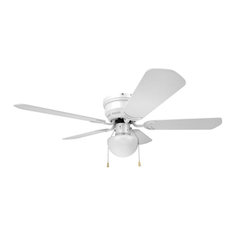
miseno mfan-9701led User manual

0
CEILING FAN
INSTALLATION INSTRUCTION
FOR FAN MODELS:
mfan-9701led, mfan-4001led, mfan-5001led,
mfan-8701led, mfan-7001led, mfan-5201led

1
SAFTY INFORMATION
1. To reduce the risk of electric shock, turn the electricity off at main fuse box or circuit breaker
before beginning fan installation or servicing the fan.
2. Read all instructions and safety information carefully before installing your fan and save this
manual.
3. All electric connections must be complied with local electrical code and the National Electrical
Code. If you are unfamiliar with electrical wiring, please have a qualified licensed electrician
perform the installation.
4. The fan must be mounted with a minimum of 7 Ft (2.1M) clearance from the trailing edge of the
bales to the floor.
5. The metal outlet box and ceiling support joist must be securely mounted, and capable of reliably
supporting a minimum of 50 lbs ( 23 kgs).
Use only UL-listed outlet boxes marked “Acceptable For Fan Support.”
6. To reduce the risk of personal injury, use only approved hanging brackets and screws supplied
with the fan for mounting to the outlet box.
7. After completing installation, check all setscrews and make sure they are firmly secure.
WARNING: To reduce the risk of fire or electric shock, do NOT use this fan with any solid-state
speed control device.
WARNING: To reduce the risk of personal injury, do NOT insert foreign objects in between rotating
fan blades.
CAUTION: To reduce the risk of personal injury, use only set screws provided with the fan for
mounting to the outlet box.
Most outlet boxes commonly used for supporting of the lighting fixture are not acceptable
for fan support and may need to be replaced.
Consult a qualified electrician if in doubt.

2
TOOL REQUIRED FOR INSTALLATION
˙Philips screwdriver ˙Straight slot screwdriver
˙Wire cutter ˙Adjustable wrench
˙Electrical tape ˙Step ladder
BEFORE INSTALLATION
˙Unpack the fan and carefully check the parts in the package.
Parts Qantity
1. Mounting bracket x1
2. Downrod/ ball assembly x1
3. Ceiling canopy x1
4. Fan motor assembly x1
5. LED Light kit fitter(light plate) x1
6. Glass shade x1
7. Blade set x 1set
8. Hardware bag included:
˙Wood screw x2
˙Flat washer x2
˙Hanging bracket screw x2
˙Spring washer x2
˙Blade screw (vary from model to model)
˙Fibber washer (vary from model to model)
˙Wood tassel x2
˙Balance kit x1set
˙Hook x1
9. Spark Plate x1

3
INSTALLING MOUNTING BRACKET & HOOK
- Insert security hook through a hole in the outlet box that allows access to the
ceiling joist and screw securely into joist.
- Secure spark plate and mounting bracket to metal outlet box using outlet box screws
and spring washers.
-Secure one more by placing two wood screws and flat washers through outer
slots of mounting bracket and park plate and into the wooden joist.
Leave one of the wood screws sufficiently loose to allow the safety cable to be looped around
before final tightening.
NOTE: For ease of wiring feed house wires through spark plate and mounting bracket.

4
- The ceiling fan must be installed in a location with a minimum of 300mm spacing from the tip of the blade
to the nearest objects or walls.
- Secure the hanging bracket to the ceiling joist or structure that is capable of carrying a load of at least 40kgs,
with two long screws provided. Ensure at least 30mm of the screw is threaded into the support.
NOTE: The bracket screws provided are for use with wooden structures only. For structures other than
wood, the appropriate screw type MUST be used.

5
DOWNROD/BALLASSEMBELY
- Take the downrod ball off from the downrod by loosening the ground wire screw, and remove a
bolt(Downrod pin).
- Rout the safety cable, white & black wires exiting the downrod, screw the downrod into collar
cover upper of the motor housing.
- Align the holes at the bottom of the downrod with the holes in the collar cover top of the motor
housing. Carefully inset the downrod pin to lock and tighten a security screw. (Fig. 1).
- Put canopy in between the downrod and ball, replace the downrod ball onto the rod. Secure the ball
with ground wire screw.
Fig. 1

6
ATTCHING THE FAN BLADES
NOTE: The hole in the foam packaging is designed to assist in holding the pre-assembled fan into position.
Insert the canopy cover end into the hole of the foam packaging to sit the motor facing up during assembly.
(Fig. 3)
- Insert the blades through the side slot of motor and align with the 3 holes.
- Secure the blades with 3 blade screws, and ensure that the 3 blade screws are tightened evenly. Do not over
tighten the screws as this can damage the blades. Repeat this process for all blades. (Fig. 2)
Fig.3
Fig.2

7
INSTALLING THE LIGHT KIT
- There are 4 pcs of screws on the switch housing as shown (Fig. 5). Two screws are for the keyholes of light
kit plate. Loosen these two screws but do not remove, take off the other 2 screws.
- Connect the lead wires of the light kit to the wires from fan motor, Black to Black and White to White.
(Fig. 4) Insert the pull chains through the side holes of the light plate.
Fig 4
-Align the keyholes of light plate to the screws of the switch housing.
-Attach the light plate to the switch housing by secruring with two screws loosen in first step. Secure the
other 2 screws taken in first step, tighten each screw firmly.
Slot
Switch housing
White Wire
White Wire
Black Wire
Black Wire
Hole
LED Light plate
Fig. 5

8
HANGINGTHE FAN
- Lift up the fan assembly onto mounting bracket.
- Ensure the notch of the ball is positioned on the stopper of mounting bracket to prevent fan from
rotating when in operation.
- Inset loop the safety cable over the hook.
ELECTRICAL CONNECTIONS
- Connect BLACK wire from the outlet box to BLACK wire(hot) & BLUE wire from fan.
- Connect WHITE wire from the outlet box to WHITE(neutral) wire from fan.
- Connect GREEN ground wire from the hanging bracket to the ground wire from outlet box.
Make sure use wire connectors provided with your fan.
NOTE: After wires are connected, carefully tuck wires back into the metal outlet box and make sure
the wires are clear of the hemisphere and downrod when positioned in mounting bracket.
ELECTRICAL CONNECTIONS ( FOR OPTIONALWALL CONTROL)
‧Follow this wiring diagram. Wall control sold separately, choose ON/OFF light control only.

9
GERNERAL INFORMATION ( FOR OPTIONAL REMOTE CONTROL)
Remote control sold separately, choose ON/OFF light control only.
FINISHINGTHE INSTALLATION
After completing the electrical connection at the mounting bracket terminal block.
Cover the mounting bracket with the canopy. Ensure all electrical wiring is tucked inside the canopy and
that they are not damaged during this step. Secure the canopy to the hanger bracket using the screws
provided. (Fig 6)
Fig. 6
Fig. 8
Carefully install the glass shade into the light fitter and twist clockwise to lock it.(Fig 8)
DO NOT over tighten when installing the glass shade into the light kit.

10
REVERSE SWITCH OPERATING INSTRUCTION
˙A slid reverse switch located on the collar cover control the direction of blades rotation.
The up position sets the blades in REVERSE rotation.
The down position sets the blades in FORWARD rotation.
SUMMER Mode: The reverse switch shall be in the “down” (SUMMER) position to make the fan rotate in
an anticlockwise direction. The airflow will be directed downwards, for cooling in summer.
WINTER Mode: The reverse switch shall be in the “up” (WINTER) position to make the fan rotate in a
clockwise direction. The airflow will be directed upwards assisting in the circulation of warm air, for energy
conservation in winter.
NOTICE: Wait for the fan to stop before changing the setting of the reverse slide switch.
OPERATION INSTRUCTION
.Connect wood tassels to two pull chains located in the light kit, one is for FAN and the other is for
LIGHT.
˙Turn on the power and check the operation of your fan.
3-SPEED PULL CHAIN- 1 pull - High Speed, 2 pulls- Medium Speed, 3 pulls- Low Speed, 4 pulls- OFF
‧To turn the light kit "ON" or "OFF, pull the chain attached to light kit.
﹗Even if the fan is mounted with a minimum of 7 feet clearance from the trailing edge of the blades to the
floor, be careful to avoid raising your arms or nay object in the path of the blades.

11
TROUBLE SHOOTING
Problem
Solution
Fan will not start.
- Check circuit fuse or breaker.
- Check wire connections to the fan and switch wire connections
in the switch housing.
* CAUTION: MAKE SURE MAIN POWER IS OFF.
Fan sounds noisy.
- Make sure all motor housing screws are snug.
- Make sure the screws attached to the fan blade bracket to the motor hub
is tight.
- Make sure wire nut connections are not rubbing against each other or
the interior wall of the switch housing.
- Make sure the upper canopy is a short distance from the ceiling.
It should not touch the ceiling.
- Allow a 24 hours break in period to eliminate most noises.
Fan wobbles
- Check all blades screws are seure.
- Most fan wobble problems are cuased when blade levels are unequal.
Check this level by slecting a point on the ceiling above the tip of one of
the blades. - Check that the downrod hemisphere notch is engaged in
canopy.
- Occasoionally slihgt weight variations would be caused by moisture
during transportation. Use the balance kits to eliminate this problem.
MAINTENANCE
Your fan requires very little maintenance.
˙Clean the housing with a damp, soft cloth (NO CLEANING AGENTS).
˙Clean the fan blades with "DRY" soft cloth or duster; moisture may cause the blades to warp.
˙If the fan starts wobbling, make sure the blades and fan are still tight and
˙Rebalance the blades if needed. It is normal to have to rebalance the fan blades after several years the fan
starts to wobble.
This manual suits for next models
5
Table of contents
Other miseno Fan manuals

miseno
miseno FF523HBN Owner's manual

miseno
miseno 7775698 User manual

miseno
miseno COOP MFAN-LP8081L User manual
miseno
miseno MBF080-WH User manual

miseno
miseno 525HBNWM User manual

miseno
miseno FF525DBN Owner's manual

miseno
miseno FF445BNSF Owner's manual

miseno
miseno MBF080AWH User manual

miseno
miseno FF425WH Owner's manual

miseno
miseno 7775693 Owner's manual