61245003L6-5E Section 61245003L6-5, Issue 5 1
Section 61245003L6-5E
Issue 5, April 2001
CLEI Code #T1L4S4TC_ _
1. GENERAL
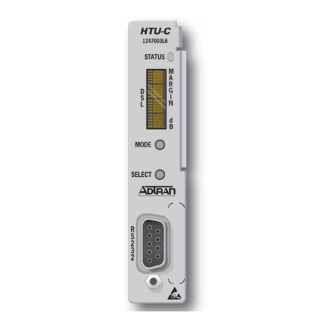
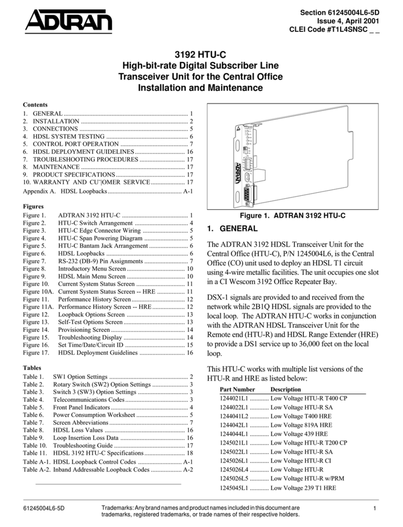
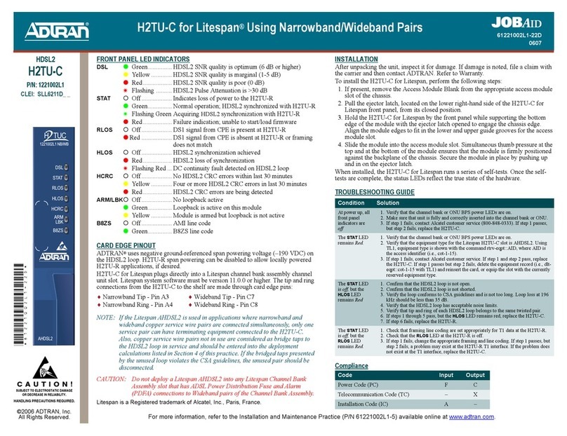
The ADTRAN DDM Plus HDSL Transceiver Unit
for the Central Office (HTU-C) (ADTRAN P N
1245003L6) is the Central Office (CO) unit used to
deploy a repeaterless T1 circuit using 4-wire
metallic facilities. The unit occupies one slot in an
AT&T DDM Plus DS1 Extension shelf. The unit is
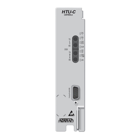
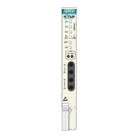
illustrated in Figure 1.
DSX-1 signals are provided to and from the network
while 2B1Q HDSL signals are provided to the local
loop. The ADTRAN HTU-C works in conjunction
with the ADTRAN HDSL Transceiver Unit for the
Remote end (HTU-R) and HDSL Range Extender
(HRE) to provide a DS1 service up to 36,000 feet on
the local loop.
This HTU-C works with multiple list versions of the
HTU-R and HRE as listed below:
• 1244021L1, Low Voltage HTU-R T400 CP
• 1244022L1, Low Voltage HTU-R SA
• 1244041LX, Low Voltage T400 HRE
• 1244042L1, Low Voltage 819A HRE
• 1244044L1, Low Voltage 439 HRE
• 1245021L1, Low Voltage HTU-R T200 CP
• 1245022L1, Low Voltage HTU-R SA
• 1245026L1, Low Voltage HTU-R CI
• 1245026L4, Low Voltage HTU-R
• 1245026L5, Low Voltage HTU-R w PRM
DDM Plus HTU-C
High-bit-rate Digital Subscriber Line
Transceiver Unit for the Central Office
Installation and Maintenance
Contents
1. GENERAL ......................................................................... 1
2. INSTALLATION............................................................... 4
3. CONNECTIONS................................................................ 6
4. HDSL SYSTEM TESTING............................................... 7
5. CONTROL PORT OPERATION...................................... 8
6. HDSL DEPLOYMENT GUIDELINES .......................... 17
7. TROUBLESHOOTING PROCEDURES ....................... 18
8. MAINTENANCE ............................................................ 18
9. PRODUCT SPECIFICATIONS ...................................... 18
10. WARRANTY AND CUSTOMER SERVICE ................ 18
Appendix A. HDSL Loopbacks........................................... A-1
Figures
Figure 1. ADTRAN DDM Plus HTU-C ............................. 1
Figure 2. DDM Plus HTU-C Option Switch Locations ..... 3
Figure 3. HTU-C Edge Connector Wiring ......................... 6
Figure 4. HTU-C Span Powering Diagram ........................ 6
Figure 5. HDSL Loopbacks ................................................ 7
Figure 6. RS-232 (DB9) Pin Assignments ......................... 8
Figure 7. Introductory Menu Screen ................................. 11
Figure 8. HDSL Main Menu Screen ................................. 11
Figure 9. Current System Status Screen ........................... 12
Figure 9A. Current System Status Screen -- HRE .............. 12
Figure 10. Performance History Screen.............................. 13
Figure 10A. Performance History Screen -- HRE................. 13
Figure 11. Loopback Options Screen ................................. 14
Figure 12. Self-Test Options Screen ................................... 14
Figure 13. Provisioning Screen ........................................... 15
Figure 14. Troubleshooting Display ................................... 15
Figure 15. Set Time Date Circuit ID .................................. 16
Figure 16. HDSL Deployment Guidelines ......................... 17
Tables
Table 1. UL CUL Telecommunications Codes .................... 3
Table 2. SW1 Rotary Switch Option Settings ...................... 4
Table 3. SW2 Option Settings .............................................. 4
Table 4. SW4 Option Settings .............................................. 4
Table 5. Power Consumption Worksheet ............................. 5
Table 6. Front Panel Indicator .............................................. 5
Table 7. Screen Abbreviations Defined................................ 8
Table 8. HDSL Loss Values ............................................... 17
Table 9. Loop Insertion Loss Data ..................................... 17
Table 10. Troubleshooting Guide ......................................... 18
Table 11. HDSL DDM Plus HTU-C Unit Specifications ... 19
Table A-1. HDSL Loopback Control Codes ........................ A-2
Table A-2. Inband Addressable Loopback Codes ................ A-3
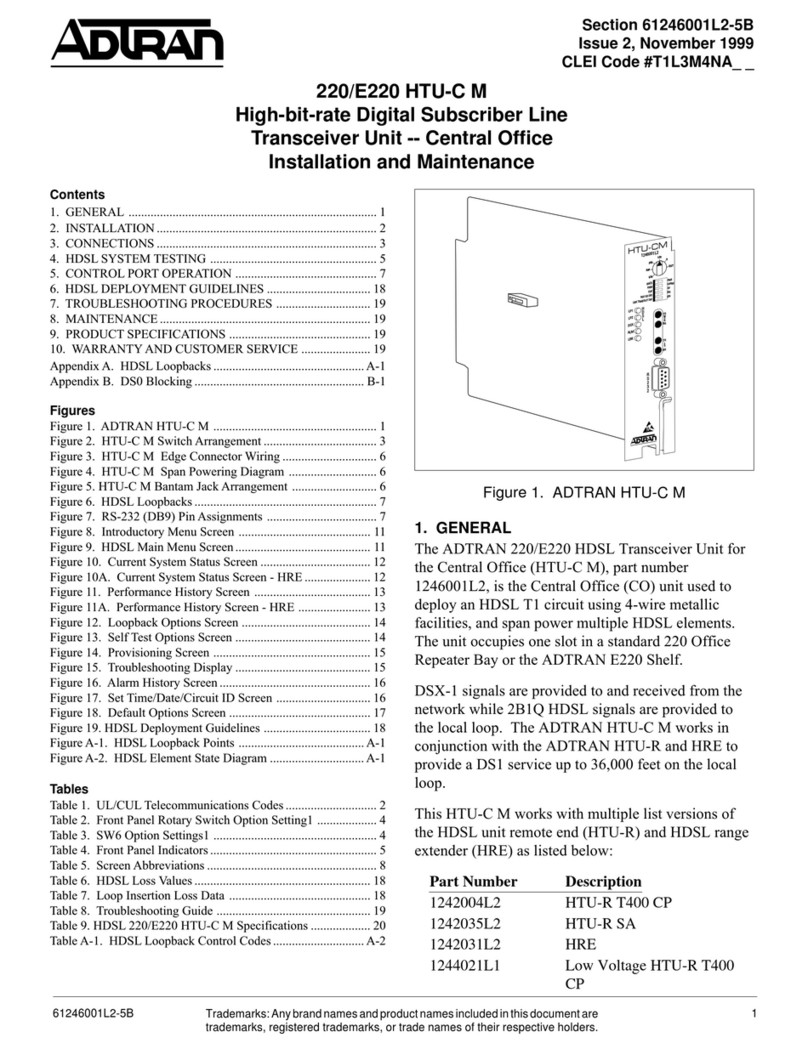
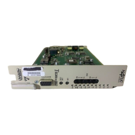
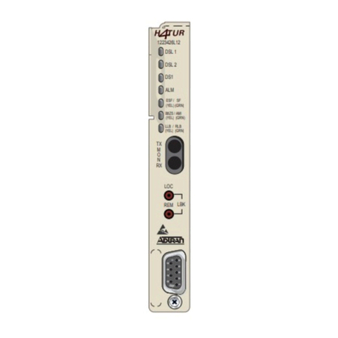
Figure 1. ADTRAN DDM Plus HTU-C
HTU-C
1245003L6
R
S
2
3
2
S
T
A
T
U
S
1
2
3
O
N
0
1
2
3
4
5
6
7
Trademarks:Anybrandnamesandproductnamesincludedinthisdocumentare
trademarks,registered trademarks,ortradenames oftheirrespoective holders.
