MITECH®srl
Uffici:
Via Roncaglia, 14
20146 Milano –Italia
Produzione:
Via Ramazzone, 23
43010 Fontevivo (PR) –Italia
Tel.: +39 02.48006383
Fax: +39 02.48025620
tech@mitech-security.com
www.mitech-security.com
MADE IN ITALY GEMINI - Rev. 07 - 10/2020- MITECH® srl si riservadi modificarei dati senza preavviso. Pagina 2 di 2
INSTALLAZIONE - ALLINEAMENTO - CAMBIO FREQUENZA - REGOLAZIONE DELLA SENSIBILITA’
1.
2.
1.
2.
3.
1.
2.
INSTALLAZIONE
Fissare le barriere in modo che siano in asse e cablare la morsettiera.
Sia sul ricevitore (RX) che sul trasmettitore (TX) verificare che tutti i dip switch siano posizionati in OFF ed alimentare i moduli.
ALLINEAMENTO (CONTROLLO LIVELLO SEGNALE)
Controllare il led rosso sul modulo ricevente, se è spento ed il cicalino non suona (per abilitare il cicalino posizionare
il dip switch 9 in ON) le barriere sono allineate. Se il led è acceso ed il cicalino suona, seguire la seguente procedura:
Sul ricevitore posizionare in ON il dip switch 8 e di seguito in ON anche il dip switch 7, NON VICEVERSA.
Nota: questa è la procedura da seguire anche se a moduli allineati si vuole solo controllare il livello segnale.
Sul display verrà visualizzato un valore di segnale, orientare quindi il gruppo ottico del ricevitore nella direzione del trasmettitore
e viceversa fino a quando il led sul modulo ricevente sarà spento ed il cicalino smetterà di suonare.
I valori sono da considerarsi ottimali se compresi tra 2,6 a 3,6 V, se il led si spegne anche sotto i 2,6 V significa che le barriere
stanno comunicando, se possibile però cercare di raggiungere comunque un valore compreso tra 2,6 e 3,6 V.
Per le regolazioni verticali agire sulla vite di regolazione, mentre per quelle orizzontali intervenire ruotando la staffa (vedere
IMMAGINE 1). Se necessario aiutarsi con il mirino (vedere IMMAGINE 2).
Una volta allineati i moduli posizionare in OFF il dip switch 8 e di seguito in OFF il dip switch 7, NON VICEVERSA.
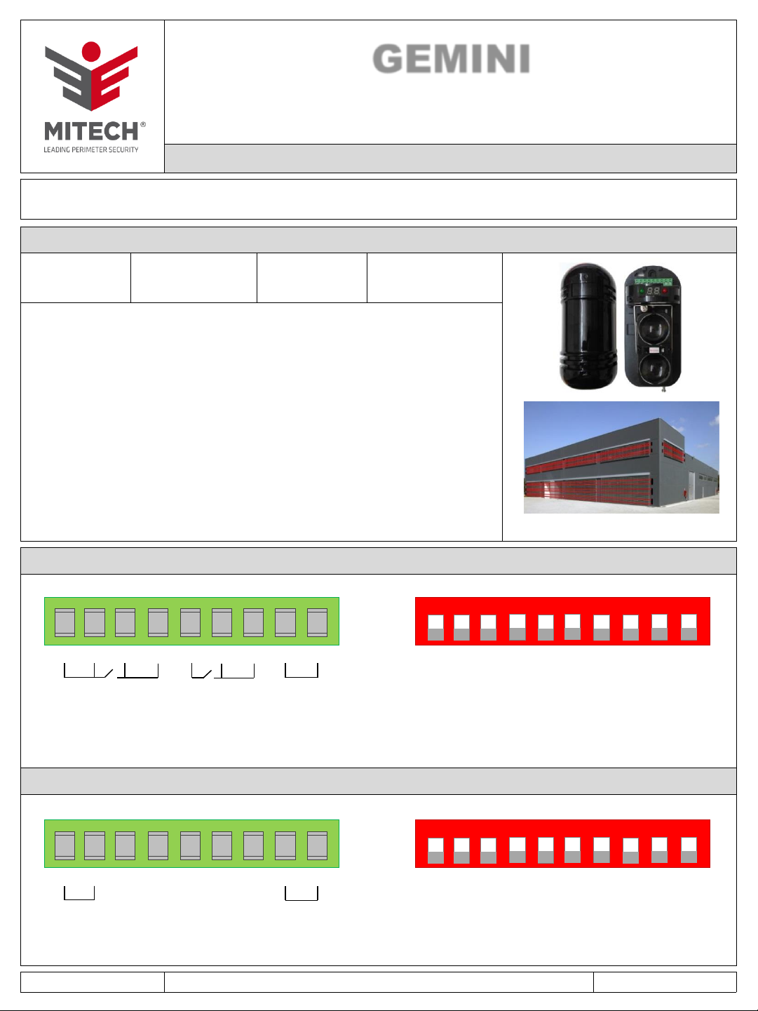
CAMBIO FREQUENZA
Per cambiare la frequenza che di default è su 1 (dip switch 1,2 e 3 in OFF),
seguire la seguente procedura:
Prima sul modulo RX e poi sul modulo TX, utilizzando i dip switch 1, 2 e 3,
settare la frequenza, vedere tabella a lato per le 8 combinazioni possibili.
Prima sul modulo RX e poi sul modulo TX confermare la frequenza posizionando
in ON il dip switch 7 e dopo un secondo riposizionandolo in OFF.
ATTENZIONE: NON LASCIARE MAI IL DIP SWITCH 7 IN ON.
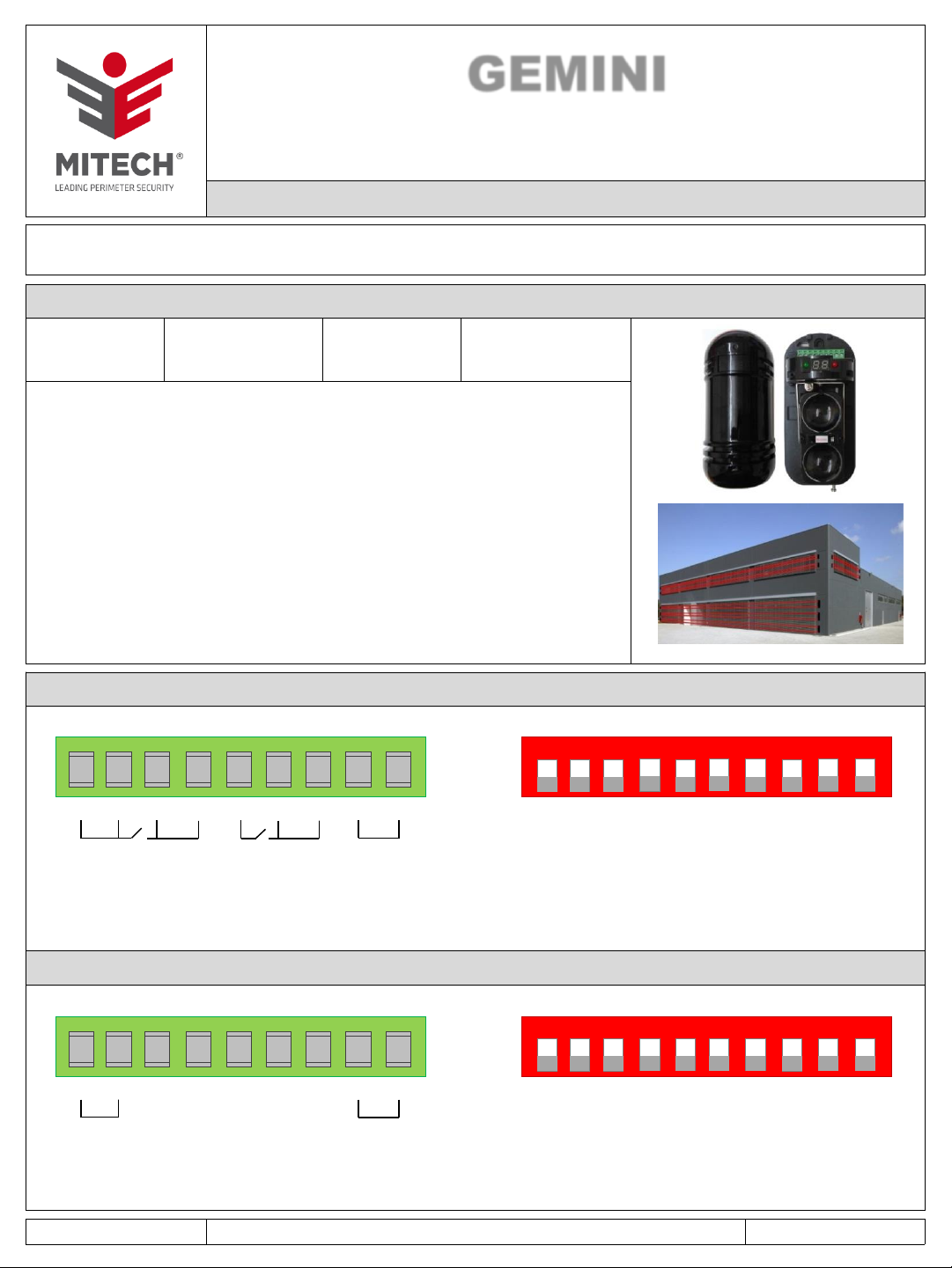
REGOLAZIONE DELLA SENSIBILITA’
Ruotare il trimmer posizionato su lato destro del ricevitore, per regolare la sensibilità.
NOTE PER L’INSTALLAZIONE
GEMINI 30
GEMINI 60
GEMINI 100
OFF ON OFF ON OFF ON OFF ON
OFF OFF ON ON OFF OFF ON ON
OFF OFF OFF OFF ON ON ON ON
NUMERO FREQUENZA (DA 1 A 8)
DIP
1
2
3
1 2 3 4 5 6 7 8
PUNTO DI OSSERVAZIONE DEL MIRINO:
porsi ad almeno 5 cm di distanza dal foro presente su entrambi i moduli
IMMAGINE 2
IMMAGINE 1
MINMAX
AVVERTENZA: IL PROGRAMMA PER IL CORRETTO FUNZIONAMENTO DELLE BARRIERE E’ LO 0.1 (IMPOSTAZIONE STANDARD)
Il programma impostato viene visualizzato in alternanza con il numero di frequenza settato. Se le barriere sono settate su un altro n° di programma (es. 0.2-0.3, ecc.), posizionare in OFF tutti i dip switch,
poi posizionare il dip switch 7 in ON e di seguito in anche il dip switch 8, NON VICEVERSA. Attendere qualche secondo poi posizionare dip switch 7 in OFF e di seguito anche il dip switch 8, NON VICEVERSA.
INSTALLAZIONE
ALLINEAMENTO (CONTROLLO LIVELLO SEGNALE)
CAMBIO FREQUENZA
REGOLAZIONE DELLA SENSIBILITA’