NC
C
NO NC
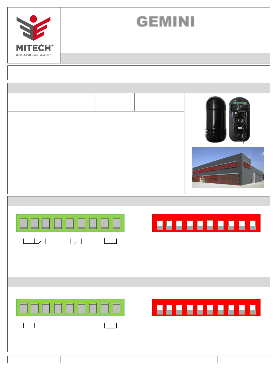
GEMINI
MINI BARRIERA ALL’INFRAROSSO ATTIVO DOPPIA LENTE
CON DISPLAY DI CONTROLLO
Disponibile in tre versioni GEMINI 30, GEMINI 60 e GEMINI 100
Istruzioni di uso ed installazione
CARATTERISTICHE TECNICHE E CONSUMI:
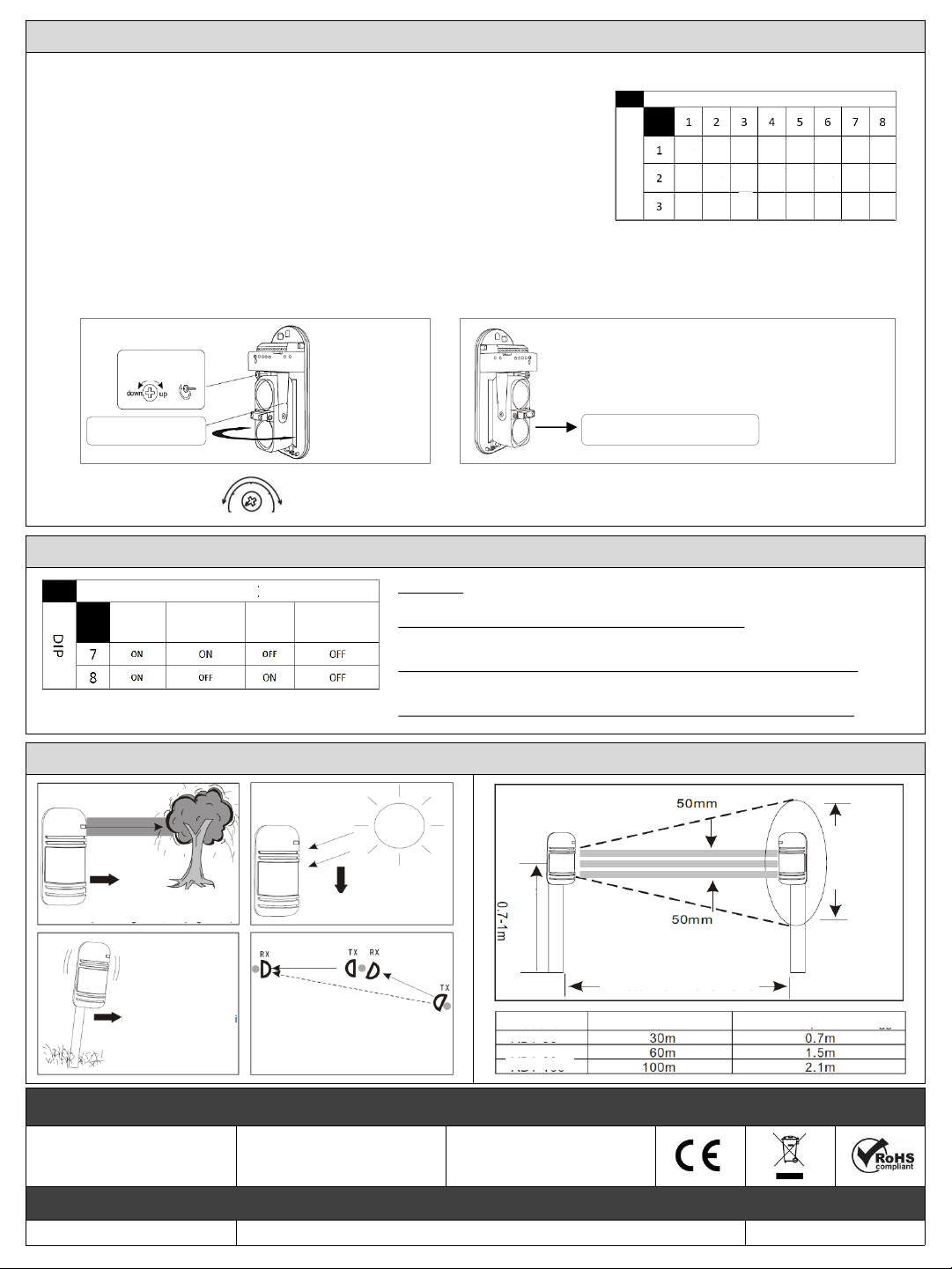
Portata massima: 100 m (GEMINI 100)
60 m (GEMINI 60)
30 m (GEMINI 30)
Portata minima:
50 m (GEMINI 100)
30 m (GEMINI 60)
15 m (GEMINI 30)
Frequenze digitali selezionabili 8
Sincronizzazione ottica
Allineamento con mirino e segnalazione a LED (il LED rosso sul profilo TX non ha alcuna funzione,
data alimentazione rimane accesso fisso fino a quando non si spegne il display agendo sul dip 10)
Angolo di rilevazione verticale 20°, orizzontale 180°
Temperatura di funzionamento da -25°C a +55°C
Disqualifica incorporata
Buzzer di allarme e di stato in fase di programmazione
Tempo di risposta regolabile tra 50 e 240m/sec.
Alimentazione da 13.8 a 24 Vdc
Assorbimento massimo 100 mA
Tensione minima di funzionamento (livello segnale) da 1,8 a 2,0 Volt (ottimale da 2,6 a 3,6)
Dimensioni 170x80x80 cm
Grado di protezione IP55
Funzionamento disqualifica: quando la potenza del segnale diminuisce lentamente fino a 0,8 V il
rilevatore attiva l'allarme anti-flog (uscita fault), quando il segnale scende a 0,4 V, allarme attivo.
MADE IN ITALY GEMINI - Rev. 05 - 01/2020- MITECH®srl si riservadi modificarei dati senza preavviso. Pagina 1 di 2
GEMINI è la mini barriera all’infrarosso attivo a doppia lente dalle dimensioni molto contenute. Precablata e pronta per l’installazione
è composta da un’unità trasmittente ed una ricevente con 8 frequenze digitali selezionabili.
DESCRIZIONE MORSETTIERA E DIP SWITCH RICEVITORE:
DESCRIZIONE MORSETTIERA E DIP SWITCH TRASMETTITORE:
9 8 7 6 5 4 3 2(-) 1(+)
NO C 1 2 3 4 5 6 7 8 9 10
ON
9 8 7 6 5 4 3 2(-) 1(+) 1 2 3 4 5 6 7 8 9 10
ON
TAMPER POWER
TAMPER FAULT ALARM POWER
1 –2: alimentazione 13,8 / 24 Vdc
3 –4 –5: uscita allarme NC o NO
6 –7 –8: uscita disqualifica (fault) NC o NO
8 –9: uscita tamper NC
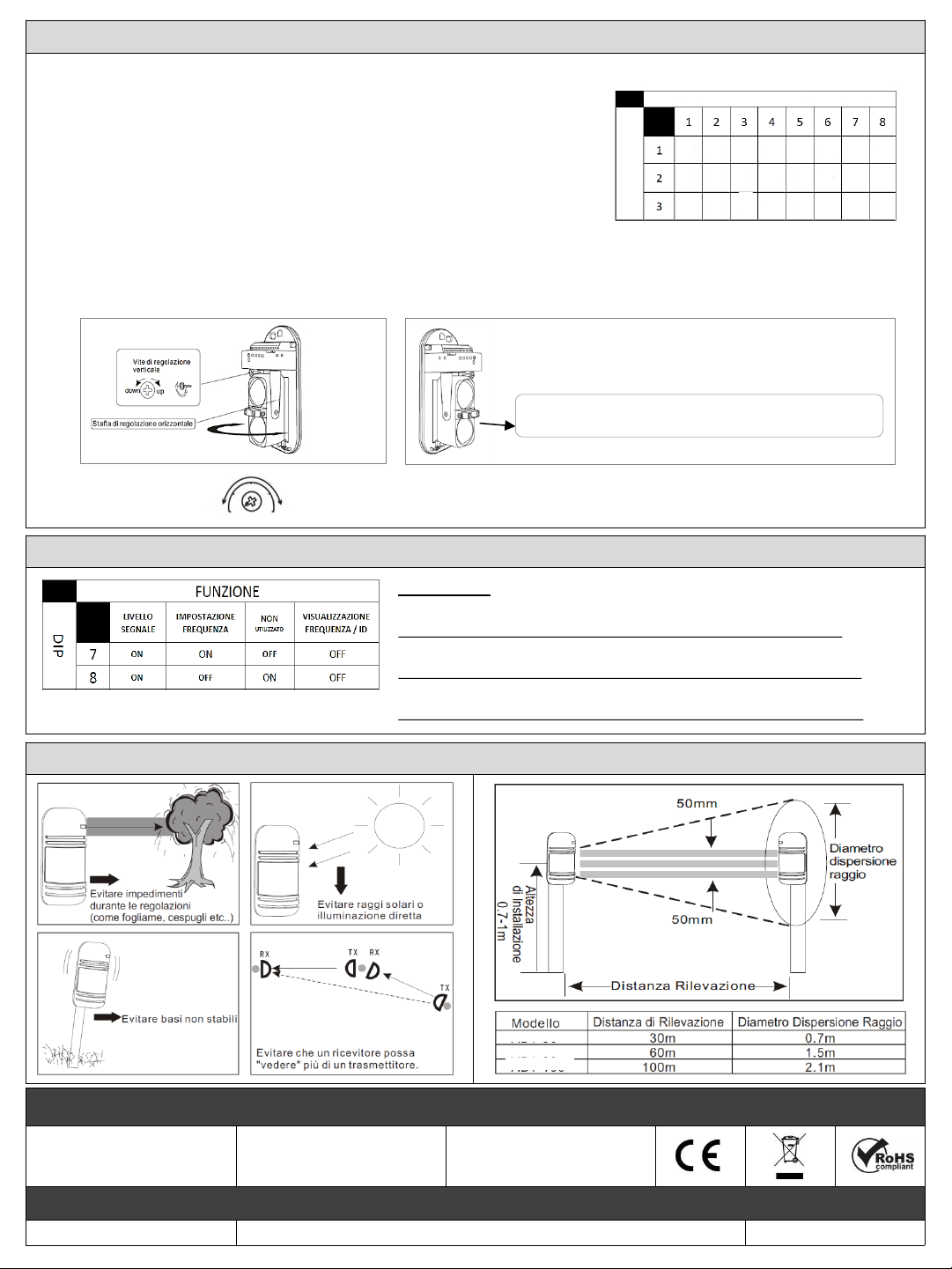
1 –2 –3: impostazione frequenza
4 –5 –6: non utilizzati
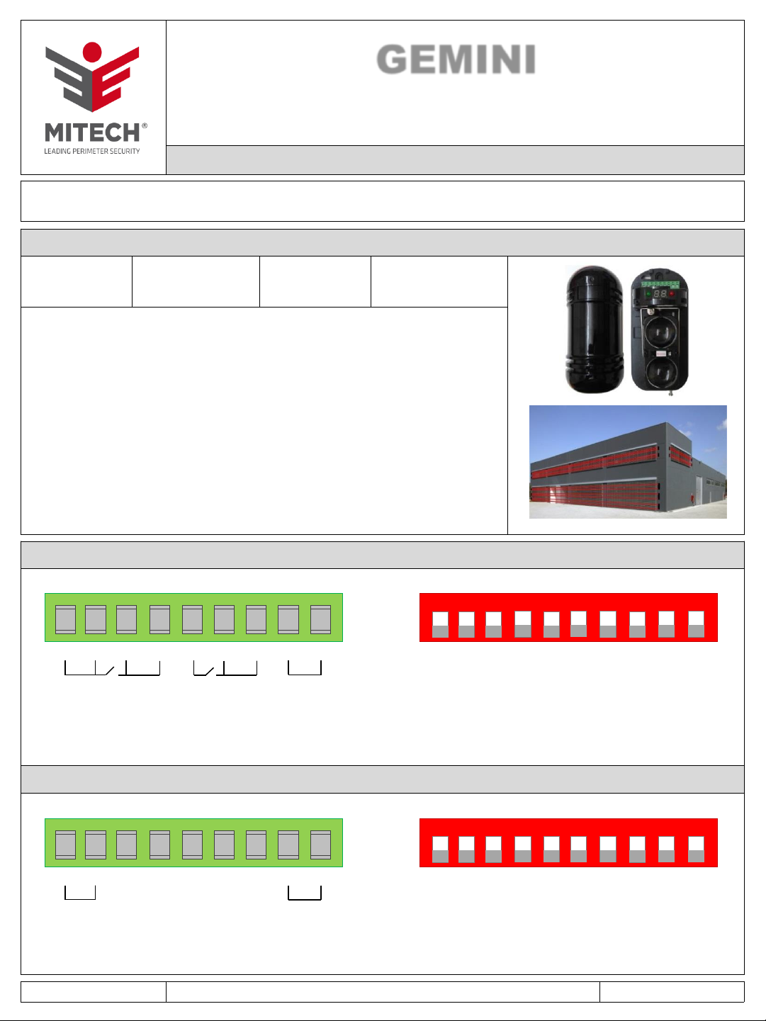
7 –8: selezione funzione (vedere TABELLA FUNZIONI a PAG.2)
9: ON/OFF cicalino
10: ON/OFF display
MORSETTIERA DIP SWITCH
MORSETTIERA DIP SWITCH
1 –2: alimentazione 13,8 / 24 Vdc
3 –4 –5 –6 –7: non utilizzati
8 –9: uscita tamper NC
1 –2 –3: impostazione frequenza
4 –5 –6: non utilizzati
7 –8: selezione funzione (vedere TABELLA FUNZIONI a PAG.2)
10: ON/OFF display