Mitsubishi Electric RD55UP12-V User manual

IoT Gateway
IBHsoftec OPC UA Server function

_________________________________________________________________________
Document: Quickstart_IoTGateway_EN Mitsubishi Electric Europe B.V.
Rev: 001G
Date: 01/02/2022 2
Table of contents
1 Relevant manuals....................................................... 4
2 Overview .................................................................... 5
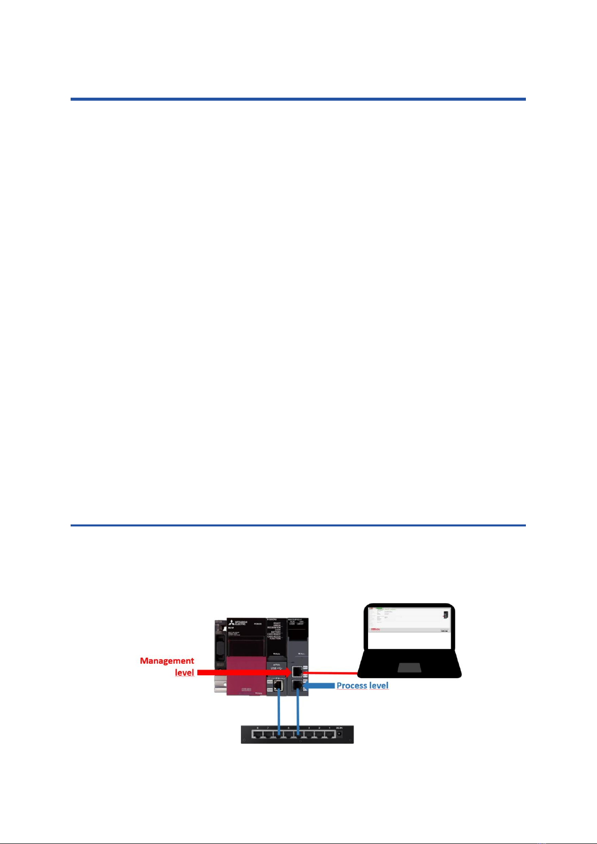
2.1 System structure...............................................................................................5
2.2 Security.............................................................................................................6
2.2.1 Encryption ..............................................................................................................................6
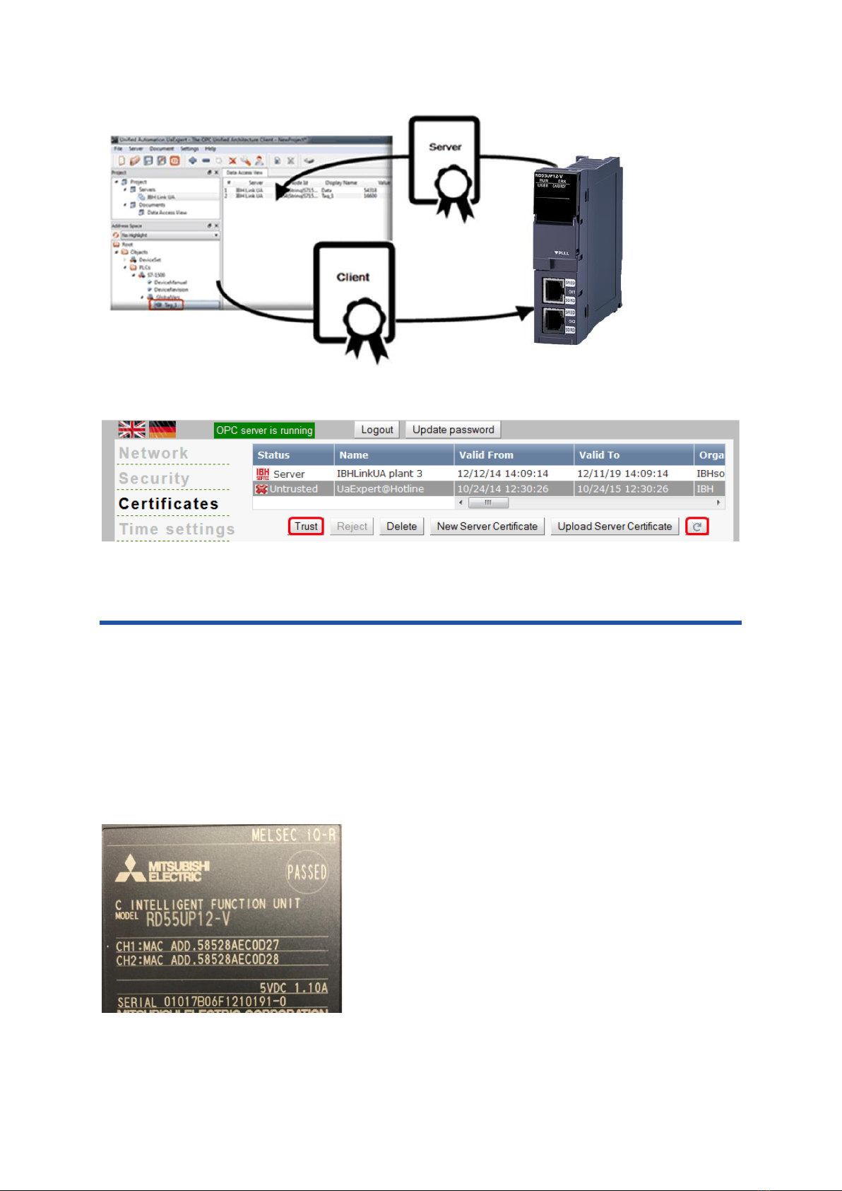
2.2.2 Certificates .............................................................................................................................6
3 Commissioning........................................................... 7
3.1 Software used...................................................................................................8
3.2 Prepare SD card...............................................................................................8
3.3 Prepare hardware .............................................................................................9
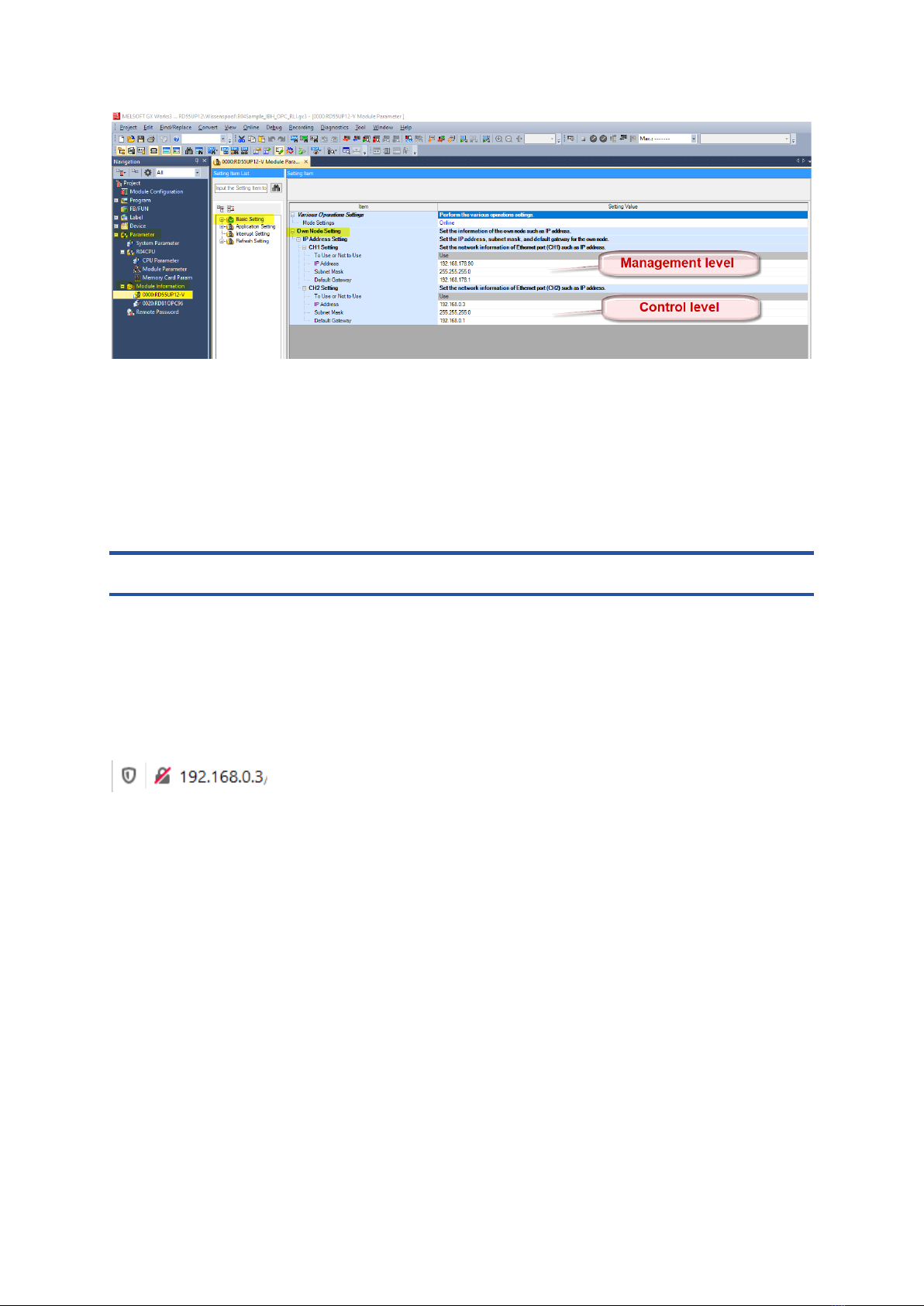
3.4 Set IP addresses for RD55UP12-V IBH............................................................9
3.5 IoT Gateway OPC UA Server Setup...............................................................10
3.5.1 Launch web interface...........................................................................................................10
3.5.2 Activate licence code ...........................................................................................................11
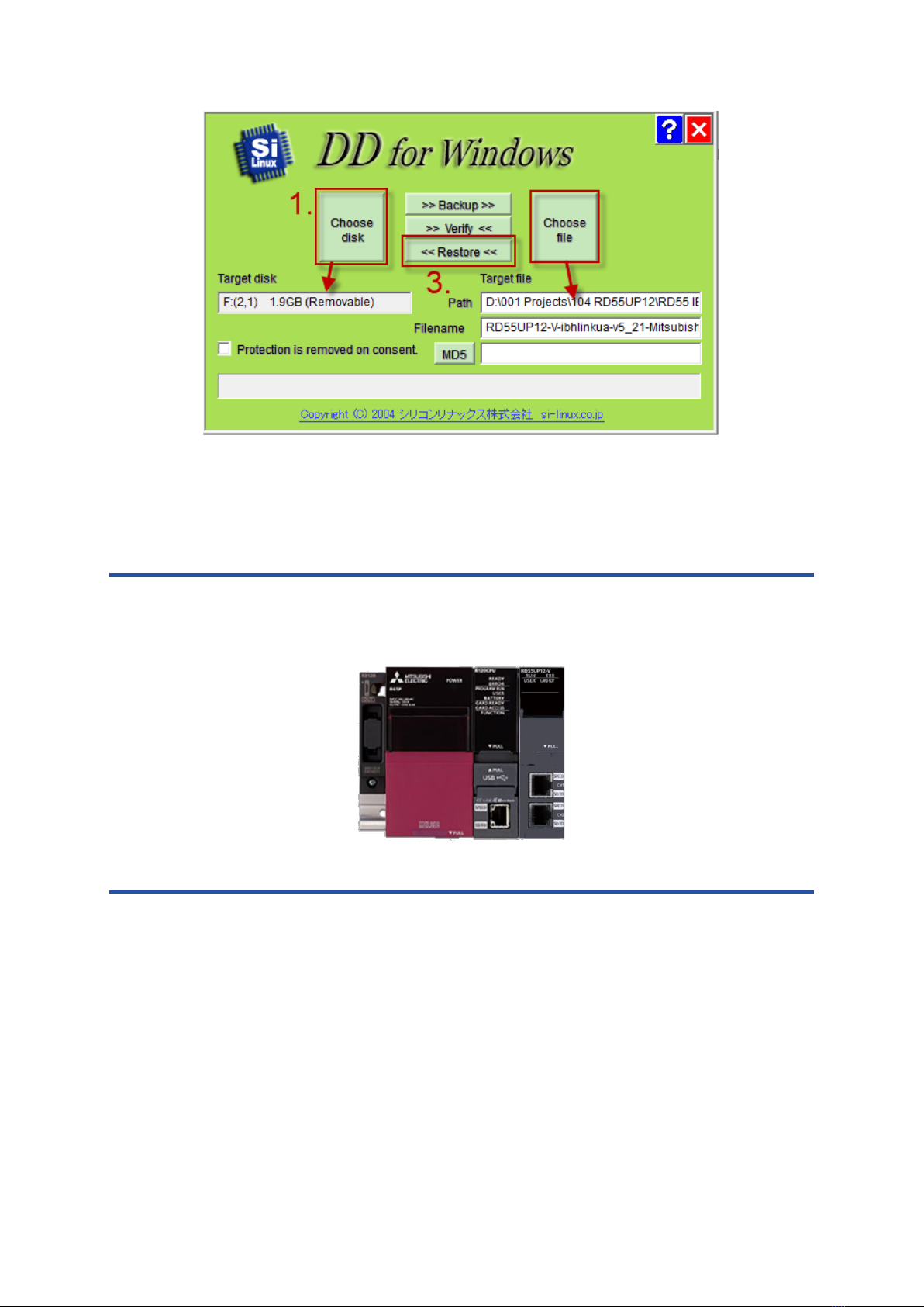
3.6 Backup / Restore of SD card...........................................................................12
3.6.1 Create Backup .....................................................................................................................12
3.6.2 Restore the SD card.............................................................................................................13
4 OPC UA server function........................................... 14
4.1 iQ-R CPU........................................................................................................14
4.1.1 Configure SLMP Connection ...............................................................................................14
4.1.2 Export global variables.........................................................................................................15
4.1.3 Add a controller via web interface........................................................................................16
4.1.4 Insert CPU............................................................................................................................16
4.1.5 Import XML file.....................................................................................................................17
4.1.6 Connect external OPC UA Client.........................................................................................19
4.2 Robot ..............................................................................................................22
4.2.1 Communication settings RT Toolbox3.................................................................................22
4.2.2 Insert robot via web interface...............................................................................................23
4.2.3 Display in the external OPC UA Client.................................................................................24
4.2.4 Add additional outputs..........................................................................................................25
4.3 Inverter............................................................................................................27
4.3.1 A800/F800............................................................................................................................30
4.3.2 E800-E .................................................................................................................................34

_________________________________________________________________________
Document: Quickstart_IoTGateway_EN Mitsubishi Electric Europe B.V.
Rev: 001G
Date: 01/02/2022 3
5 Diagnostics............................................................... 37
5.1 Controller diagnostics......................................................................................37
5.2 Client diagnostics............................................................................................37
5.3 Network diagnostics........................................................................................38
5.4 System log......................................................................................................40
6 OPC Client Function Example.................................. 43
7 MODBUS.................................................................. 45
7.1 Add MODBUS Configuration...........................................................................45
7.2 Add Variables..................................................................................................46
7.3 Usage of MODBUS-Data................................................................................48
8 MQTT Settings......................................................... 50
8.1 Create new Broker connection........................................................................50
8.2 Publish of values (Send data to Broker)..........................................................51
8.2.1 Create Topic.........................................................................................................................51
8.2.2 Create new variable (data to be sent)..................................................................................53
8.2.3 Check data in Broker............................................................................................................54
8.3 Subscription to values (receive data from broker)...........................................54
8.3.1 Create Topic.........................................................................................................................54
8.3.2 Create new variable.............................................................................................................55
8.3.3 Function test of “Subscribe” .................................................................................................56
9 Teamviewer IoT Connection..................................... 57
9.1 PC preparations - connected to the Ethernet port of the control level.............58
9.1.1 TeamViewer Software..........................................................................................................58
9.1.2 IBHNet IoT setup..................................................................................................................59
9.1.3 TeamViewer IoT Management Console ..............................................................................59
9.1.4 Connection setup.................................................................................................................63
9.2 Access to controllers (CPUs / devices) that are connected to the ports of the
control level...........................................................................................................66
9.2.1 iQ-R CPU .............................................................................................................................66
9.2.2 Robot....................................................................................................................................67
9.2.3 GOT......................................................................................................................................69

_________________________________________________________________________
Document: Quickstart_IoTGateway_EN Mitsubishi Electric Europe B.V.
Rev: 001G
Date: 01/02/2022 4
1 Relevant manuals
This "Quick Start Manual" only describes the necessary steps to put the hardware into
operation and to parameterise the corresponding functions.
Further details can be found in the relevant manuals.
Manual name [manual number]
Description
MELSEC iQ-R C intelligent function module
Linux Startup manual (Copyright© 2008-2020
Lineo Solutions, Inc. All rights reserved)
MELSEC iQ-R C Intelligent Function Module
User's Manual (Startup)
[SH-081566ENG]
Specifications, procedure before operation, wiring, and
operation examples of a C intelligent function module
MELSEC iQ-R C Intelligent Function Module
User's Manual (Application)
[SH-081567ENG]
Functions, input/output signals, buffer memory, parameter
setting, and troubleshooting of a C intelligent function
module
MELSEC iQ-R Module Configuration Manual
[SH-081222ENG]
The combination of the MELSEC iQ-R series modules,
common information on the installation/wiring in the system,
and specifications of the power supply module, base unit,
SD memory card, and battery
MELSEC iQ-R C Intelligent Function Module
Programming Manual
[SH-081568ENG]
Programming specifications and dedicated function libraries
of a C intelligent function module
MELSEC iQ-R C Controller Module/C
Intelligent Function Module Programming
Manual (Data Analysis)
[SH-081756ENG]
Programming specifications and dedicated function libraries
for analysing the data of a C controller module and a C
intelligent function module
CW Workbench/CW-Sim Operating Manual
[SH-081373ENG]
System configuration, specifications, functions, and
troubleshooting of CW Workbench/CW-Sime-Manual
GX Works3 Operating Manual
[SH-081215ENG]
System configurations, parameter settings, and operation
methods for the online function in GX Works3
GT Designer3 (GOT2000) Screen Design
Manual [SH-081220ENG]

_________________________________________________________________________
Document: Quickstart_IoTGateway_EN Mitsubishi Electric Europe B.V.
Rev: 001G
Date: 01/02/2022 5
2 Overview
Under the catchword "Industry 4.0", more and more new communication and information
technologies are finding their way into industrial automation. In order to be able to
implement these requirements efficiently and as quickly as possible, attempts must be
made to reduce the high level of complexity through modularisation and standardisation.
In this context, OPC UA has proven to be a forward-looking communication standard.
This is because OPC UA fulfils the Industry 4.0 requirement for independence from
manufacturer, industry and operating system communication.
Since OPC UA not only transmits machine data, i.e. process values and measured
values, but can also describe them semantically, OPC UA is becoming increasingly
important when it comes to transferring machine data from controllers to higher-level
systems.
One solution for reading process data from Mitsubishi Electric controllers and robots that
do not have an OPC interface as standard is the RD55UP12-V module with installed IBH
Link UA software, called IoT Gateway.
This solution is a server/client module. The OPC client function also enables OPC servers
to exchange data with each other. For example, controllers or other devices with OPC UA
from different manufacturers can exchange data via this function.
Communication with the controller is via TCP/IP.
The IoT Gateway has an Ethernet port for the machine level and an Ethernet port for the
control level.
Only OPC accesses are possible on the control level. A firewall is integrated between the
two levels. The ports are configured via the GX-Works3 programming software of the iQ-R
CPU.
2.1 System structure
As a minimum configuration, the IoT Gateway always requires a base rack, an iQ-R CPU
and the RD55UP12-V module. To establish a connection to several controllers, a switch is
required at the process level.

_________________________________________________________________________
Document: Quickstart_IoTGateway_EN Mitsubishi Electric Europe B.V.
Rev: 001G
Date: 01/02/2022 6
2.2 Security
The IoT Gateway has a certificate management for secure communication. A corresponding
software interface is supplied for this purpose, which can be displayed in any web browser.
The configuration of the security levels and the administration of the certificates are carried
out in this interface. This is based on the mechanisms defined by the OPC Foundation. OPC
UA Security includes authentication and authorisation, encryption and data integrity through
signing. In this way, the control system can be protected against uncontrolled access via a
higher-level system.
2.2.1 Encryption
There are different levels of encryption (Encrypt): None, Basic128Rsa15 and Basic256.
None
No encryption
Basic128Rsa15
128 bit encryption
Basic256
256 bit encryption
The IBH Link UA function supports the Level Sign and SignAndEncrypt
None
No security level, fastest data transmission
Sign
The messages contain signed certificates
Sign and Encrypt
The messages contain signed certificates and are encrypted
Sign + Sign and
Encrypt
The messages may contain only signed certificates, or can be
signed and are encrypted as well
2.2.2 Certificates
Another security level of OPC UA is the exchange of certificates. Communication is only
possible when both server and client have been assigned a valid certificate by the respective
partner.

_________________________________________________________________________
Document: Quickstart_IoTGateway_EN Mitsubishi Electric Europe B.V.
Rev: 001G
Date: 01/02/2022 7
3 Commissioning
Each RD55UP12-V can be started as an IoT Gateway module. For this purpose, a
corresponding image must be written to an SD card.
The image file contains the Linux operating system and the corresponding programme from
IBH for the OPC UA server function.
In order to be able to use the OPC UA server function without restriction, it must be activated
for the hardware used with a licence code created at IBH. For this purpose, the serial
number and MAC addresses from the type plate of the module are required.

_________________________________________________________________________
Document: Quickstart_IoTGateway_EN Mitsubishi Electric Europe B.V.
Rev: 001G
Date: 01/02/2022 8
3.1 Software used
Product
Description
DDWIN ( Download link: http://download.si-
linux.co.jp/dd_for_windows/DDWin_Ver0998.zip )
Program for writing the
IBHsoftec image file to
an SD card
UaExpert
( Download link: https://www.unified-
automation.com/de/downloads/opc-ua-clients.html )
Free OPC UA client
program for testing the
server function
MELSOFT GX Works3 EU version
Programming tool for
programming the iQ-R
CPU
GT Designer3
Programming tool for
HMIs of the GOT
series
RT Toolbox3
Programming tool for
robots
IBH OPCUA Edit
https://download.ibhsoftec.com/neutral/IBHOPCUAEditor749Setup.exe
Offline Configuration
tool for IoT Gateway
In addition, a web browser must be installed on the PC.
If you have received an already configured IoT Gateway from Mitsubishi Electric, the
following setup chapters 3.2 to 3.5 are not required.
For your security, we recommend that you create a backup copy of the inserted SD card, as
described in Chapter 3.6.
3.2 Prepare SD card
To write the image file with the Linux OS to an SD card, you need the programme "DDWIN"
on a Windows computer. After downloading, the ZIP file must be unpacked, an SD card
inserted into the PC and the file "DDWIN.EXE" executed as administrator.
1. Select the SD card in the PC under "Choose disk".
2. Select the Linux image file from IBHsoftec under "Choose file".
3. Select "<<Restore>>".

_________________________________________________________________________
Document: Quickstart_IoTGateway_EN Mitsubishi Electric Europe B.V.
Rev: 001G
Date: 01/02/2022 9
When writing to the SD card is finished, the "DDWIN" program can be closed and the SD
card removed from the PC and inserted into the RD55UP12-V module.
3.3 Prepare hardware
Unpack the selected iQ-R hardware, mount it to the base rack and connect it as instructed
(refer to Mitsubishi Electric hardware manuals). The control unit can now be switched on.
3.4 Set IP addresses for RD55UP12-V IBH
First, you have to create a project in GW-Works3 that matches the hardware you have
plugged in.
Under "Parameters" →"Module Information" →RD55UP12-V "→Basic Setting" →"Own node
setting" the IP addresses for the control and process level can then be set.

_________________________________________________________________________
Document: Quickstart_IoTGateway_EN Mitsubishi Electric Europe B.V.
Rev: 001G
Date: 01/02/2022 10
Once all settings have been made, the new project is transferred to the CPU. The control
unit must be switched off and on again once after the transfer.
The channel "CH1" of the RD55 module is now in the address range of the management
level and the channel "CH2" is in the range of the control level.
3.5 IoT Gateway OPC UA Server Setup
3.5.1 Launch web interface
Depending on the level via which the PC is connected to the IoT Gateway, the
parameterisation interface can be called up by entering the corresponding IP address in a
web browser.
In the following example, the PC is connected via the process level, only "192.168.0.3" is
entered in the browser.
The login screen is displayed. For a new system, the default user name and password are
both "admin".

_________________________________________________________________________
Document: Quickstart_IoTGateway_EN Mitsubishi Electric Europe B.V.
Rev: 001G
Date: 01/02/2022 11
After pressing "Log in", you are in the configuration interface.
3.5.2 Activate licence code
After you have received the license file from IBHsoftec matching the module serial number
and MAC addresses, this must be imported into the module once.
To do this, select the "System" menu in the configuration interface.

_________________________________________________________________________
Document: Quickstart_IoTGateway_EN Mitsubishi Electric Europe B.V.
Rev: 001G
Date: 01/02/2022 12
On this page, click on "Browse" at "Select licence file" to search for the corresponding file
and then click on "Upload licence file" to copy it to the SD card.
After a restart of the system, the IoT Gateway can be used without restrictions.
The basic set-up of the IoT Gateway is now complete. The individual functions are explained
in the following chapters.
3.6 Backup / Restore of SD card
After all the necessary configurations have been made and the project functions have also
been parameterized, a backup copy can be created from the SD card using the "DDWIN"
software. This backup can only be used in the RD55UP12-V module with the hardware ID
for which the IoT Gateway license was created.
3.6.1 Create Backup
To create the backup, switch off the controller with the IoT Gateway and remove the SD card
from the IoT Gateway module. Insert the SD card into the PC and run the "DDWIN.EXE"
program as administrator.
1. Select the SD card in the PC under "Choose disk"
2. Select a drive path under "Choose file" and enter the desired file name
3. Select „>>Backup>>“

_________________________________________________________________________
Document: Quickstart_IoTGateway_EN Mitsubishi Electric Europe B.V.
Rev: 001G
Date: 01/02/2022 13
The data will now be read from the SD card
The SD card can now be reinserted into the IoT Gateway and the controller can be started.
3.6.2 Restore the SD card
To load the image onto a new SD card, the "DDWIN.EXE" program must be run as an
administrator
Then insert a new SD card into the PC

_________________________________________________________________________
Document: Quickstart_IoTGateway_EN Mitsubishi Electric Europe B.V.
Rev: 001G
Date: 01/02/2022 14
1. Select the SD card in the PC under "Choose disk"
2. Select the previously created backup copy under "Choose file".
3. Select „<<Restore<<“
After the message "Writing has completed ..." the SD card can be plugged into the
corresponding RD55UP12-V module and then the controller can be switched on.
4 OPC UA server function
This chapter explains how to connect the IoT Gateway to controllers and make their global
variables available as OPC UA tags for clients.
4.1 iQ-R CPU
4.1.1 Configure SLMP Connection
In order for the Mitsubishi controller to be accessible via OPC UA, the SLMP Connection
Module must be inserted using the GX Works configuration software.
Important: In order for data to be written externally to the OPC UA tags, "Enable all (SLMP)"
must be selected!

_________________________________________________________________________
Document: Quickstart_IoTGateway_EN Mitsubishi Electric Europe B.V.
Rev: 001G
Date: 01/02/2022 15
4.1.2 Export global variables

_________________________________________________________________________
Document: Quickstart_IoTGateway_EN Mitsubishi Electric Europe B.V.
Rev: 001G
Date: 01/02/2022 16
4.1.3 Add a controller via web interface
Insert station
4.1.4 Insert CPU

_________________________________________________________________________
Document: Quickstart_IoTGateway_EN Mitsubishi Electric Europe B.V.
Rev: 001G
Date: 01/02/2022 17
4.1.5 Import XML file
The European version of GX Works 3 offers the function to export the project as an XML file.
→
The file created by this function can be uploaded to the IoT Gateway web server.

_________________________________________________________________________
Document: Quickstart_IoTGateway_EN Mitsubishi Electric Europe B.V.
Rev: 001G
Date: 01/02/2022 18
Now all global variables of the imported project are automatically available in the OPC UA
Server.

_________________________________________________________________________
Document: Quickstart_IoTGateway_EN Mitsubishi Electric Europe B.V.
Rev: 001G
Date: 01/02/2022 19
4.1.6 Connect external OPC UA Client
The free UaExpert is used here as a test client.
https://www.unified-automation.com/de/downloads/opc-ua-clients.html

_________________________________________________________________________
Document: Quickstart_IoTGateway_EN Mitsubishi Electric Europe B.V.
Rev: 001G
Date: 01/02/2022 20
Table of contents