Mitsubishi Electric MELDAS 600 Series User manual

MITSUBISHI CNC
MELD/IS
600
Series
MAINTENANCE TOOL
INSTRUCTION MANUAL
BNP-63988-001* (ENq
ADVANCED AND EVER AOVANCING
Mll’SlJBlSHl ELECTRIC

Revision History
Sub-No.
*
Date of revision
June 1999
Revision details
First edition created.

CONTENTS
1. Outline .........................................................................................................................................
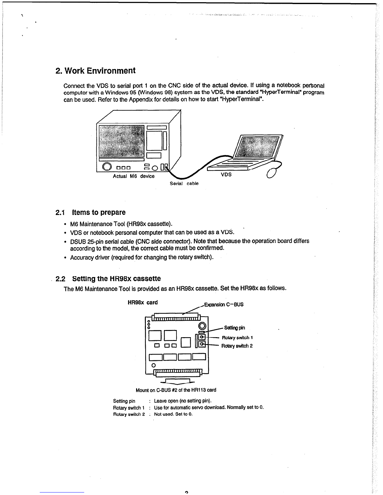
2. Work Environment ..............................................................................................................................
2.1 Items to prepare.. ........................................................................................................................
2.2 Setting the HR98x caxx$te .......................................................................................................
2.3 Mounting the maintenance tool cassette.. ..................................................................................
3. Starting and Ending the M6 Maintenance Tool ..............................................................................
3.1 Starting the tool ...........................................................................................................................
3.2 Ending the tool.............................................................................................................................
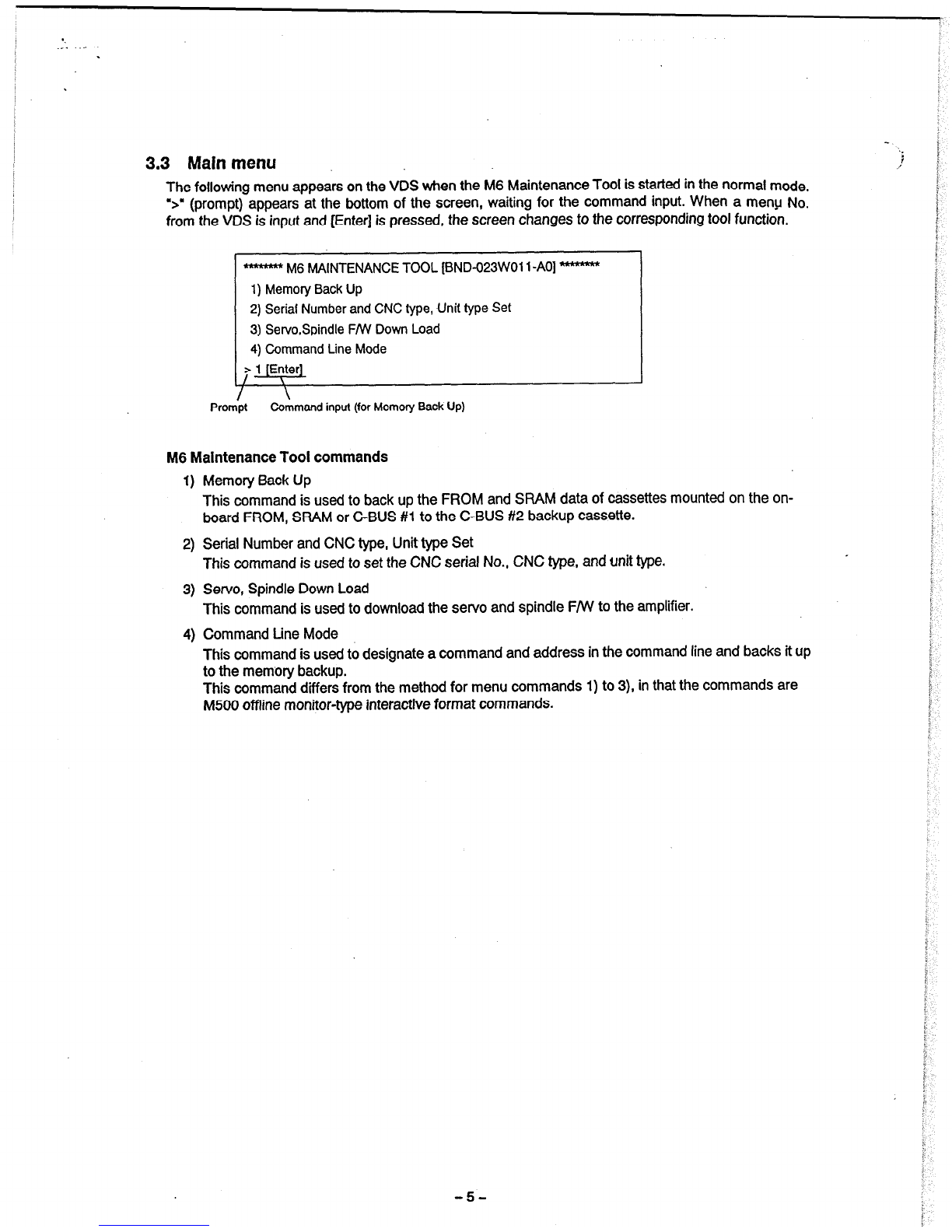
3.3 Main menu.. .................................................................................................................................
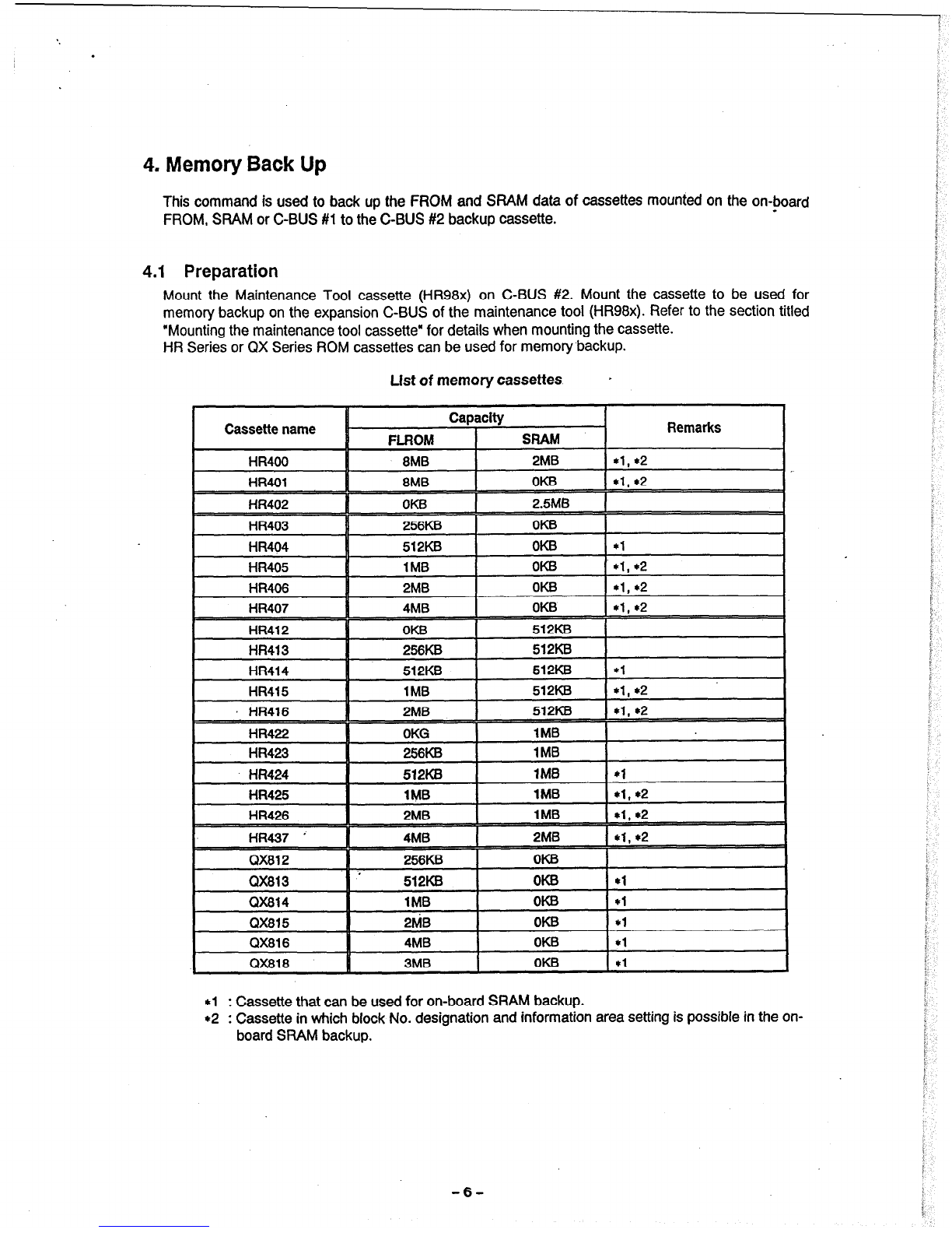
4. Memory Back Up .................................................................................................................................
4.1 Preparation ..................................................................................................................................
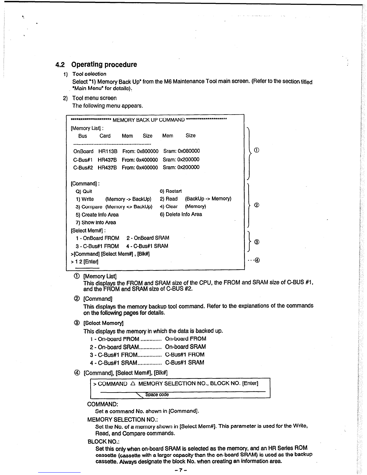
4.2 Operating procedure ...................................................................................................................
4.3 Explanation of commands ..........................................................................................................
4.4 Emr messages.. .........................................................................................................................
5. Serial Number and NC Typk, Unit type Set .....................................................................................
5.1 Preparation ..................................................................................................................................
5.2 Operating procedure ...................................................................................................................
6. Servo Spindle FNV Down Load.. ........................................................................................................
6.1 Preparation ..................................................................................................................................
6.2 Starting the tool ...................................................................................... .....................................
6.3 Operating proce&re in the normal mode.. .................................................................................
6.3.1 Initial screen .....................................................................................................................
6.3.2 Operation display.. ...........................................................................................................
6.3.3 Error information ..............................................................................................................
6.4 Operating procedure in the automatic firmware download mode .............................................
6.4.1 Operation proc&,re.. ......................................................................................................
6.4.2 List of error Nos ...............................................................................................................
6.5 Internal mnfigur&on of the M500 Maintenance Tool CaSSetk.. ...............................................
7. Command Line Mode ..........................................................................................................................
7.1 Outline ........................................................................................................................................
7.2 Memory map ....................................... .......................................................................................
7.3 l& of cammlds.. ......................................................................................................................
7.4 &mmand format.. ......................................................................................................................
7.5 Explanation of comma& ..........................................................................................................
7.5.1 End command line tool.. ..................................................................................................
7.5.2 Display help.. ....................................................................................................................
7.5.3 Display memory information ............................................................................................
7.5.4 Display memory.. .............................................................................................................
7.5.5 Modify memory.. ..............................................................................................................
7.5.6 Write FROM.. ...................................................................................................................
7.5.7 Erase FROM ...................................................................................................................
7.5.8 copy memory ..................................................................................................................
7.5.9 W&e memory.. ................................................................................................................
7.510 Clear memory.. ................................................................................................................
7.5.11 Compare memory.. ..........................................................................................................
7.5.12 meate a wpy of the M6 Maintenance Tool ....................................................................
8. Appendix 1 HyperTermlnal Starting Procedure ............................................................................
1
2
2
2
3
4
4
4
5
6
6
7
8
15
16
16
16
18
18 .
18
19
19
20
22
23
23
24
25
27
27
27
28
28
29
29
29
29
30
31
32
33
33
34
34
34
35
36

c.
:. >
1. Outline
The M6 Maintenance Tool is used when performing maintenance on a CNC shipped to the machine
maker, end user, etc. The tool has the following functions.
1) Memory Backup function
2) Serial number, CNC type and unit type setting function
3) Servo, spindle F/w download function
4) Memory backup by command line function
The M6 Maintenance Tool is provided as an HR98x cassette, and is used mounted on C-BUS #2 of the
CNC. The M6 Maintenance Tool is operated usina a VDS. Because of this, a VDS and cable that can
be connected to the CNC are required.
[Supplement]
*l : System, boot ROM upgrades
. The system and boot ROM are not upgraded by the maintenance tool. These are upgraded
using cassettes specially dedicated for upgrading.
*2 :’ PLC (ladder) upgrades
PLc’s are upgraded following the appropriate method for each model.
-l-

2. Work Environment
Connect the VDS to serial port 1
on the CNC
side of the actual device. If using a notebook personal
computer with a Windows 95 (Windows 98) system as the VDS, the standard “HyperTerminal” program
can be used. Refer to the Appendix for details on how to start “HyperTerminal”.
Serial
cable
2.1 Items to prepare
l
M6 Maintenance Tool (HR98x cassette). *
l
VDS or notebook personal computer that can be used as a VDS.
l
DSUB 25pin serial cable (CNC side connector). Note that because the operation board differs
according to the model, the correct cable must be confirmed.
l
Accuracy driver (required for changing the rotary switch).
2.2 Setting the HR98x castiette
The M6 Maintenance Tool is provided as an HR98x cassette. Set the HR98x as follows.
HR98x card ,Expa”s’l C-BUS
Mounton
C-BUS #2 of the HR113 card
Setting pin : Leave open (no setting pin).
Rotary switch 1 : Use for automatic servo download. Normally set to 0.
Rotary switch 2 : Not used. Set to 0.
-3-

2.3 Mounting the maintenance tool cassette
The following shows the cassette mounting location.
1) The maintenance tool (HR98x cassette) is mounted on C-BUS #2 of the HR113 or HRl 11 card.
2) Depending on the functions to be used, cassettes for memory backup or cassettes for copying
FROM cassettes may be mounted in addition to the maintenance tool (HR98x cassette). Mount the
cassettes using the following drawing as a reference.
(Note) Always mount/remove cassettes with the CNC power OFF
Back view of
unit
ir-segment LED \ CN6 reset
Rotary switch
I Memory cassette I
Espansion C-BUS
(EXTC-BUS)
Roteryswfich 1
Rotary switch 2
1
Mount the HR96x card on C-BUS #2
El
Memorycessette

..:
3. Starting and Ending the M6 Maintenance Tool
3.1 Starting the tool
Two types of start modes can be selected by setting the rotary switch on top of the main CPU
(HFil KM-Ml 11) (The rotary switch always returns to its original setting after the operation is completed,
so check the current setting to be sure it is correct.)
CPU rotary
switch Start mode Outline
Set the main CPU rotary switch to “B”, and turn ON the CNC power.
B Normal mode The maintenance tool menu screen will appear on the VDS. Select
the required tool from the menu and execute. The servo download
function can also be carried out in the normal mode.
Set the main CPU rotary switch to “9”. Set the HR98x rotary switch
Automatic servo 1 to the number of the module to be downloaded, and turn ON the
9 F/W download CNC power. The selected module will be automatfcaiiy~
mode downloaded. Refer to the section titled ‘Servo and spindle
downloading’ for details.
* Supplement : When starting the maintenance tool by a CNC with personal computer,
the tool will not be started if the personal computer side is in a reset status.
3.2 Ending the tool
Turn OFF the CNC power when the operation is finished. The personal computer side is not started
even for a CNC with personal computer, so there is no problem if the CNC power is turned OFF in this
state.
After turning OFF the CNC power, remove the M6 Maintenance Tool cassette and any other cassettes
used in the maintenance. Return the main CPU rotary switch to the setting it was at before carrying out
the operation.
-4-

‘.
3.3 Main menu
The following menu appears on the VDS when the M6 Maintenance Tool is started in the normal mode.
5” (prompt) appears at the bottom of the screen, waiting for the command input. When a menu No.
from the VDS is input and [Enter] is pressed, the screen changes to the corresponding tool function.
**hm** M6 MAINTENANCE TOOL [BND-O23WOll -AO] *wnHr*r\*
1)
Memory Back Up
2) Serial Number and CNC type, Unit type Set
3) Setvo,Spindle F/w Down Load
4) Command Line Mode
> 1 [Enter]
\
/ \
Prompt Command input (for Memory Back Up)
M6 Maintenance Tool commands
I) Memory Back Up
This command is used to back up the FROM and SFtAM data of cassettes mounted on the on-
board FROM, SFtAM or C-BUS #l to the C-BUS #2 backup cassette.
2) Serial Number and CNC type, Unit type Set
This command is used to set the CNC serial No., CNC type, and unit type.
3) Servo, Spindle Down Load
This command is used to download the servo and spindle F/w to the amplifier.
4) Command tine Mode
This command is used to designate a command and address in the command line and backs it up
to the memory backup.
This command differs from the method for menu commands 1) to 3), in that the commands are
M500 offline monitor-type interactive format commands.
-5-

4. Memory Back Up
This command is used to back up the FROM and SFWM data of cassettes mounted on the on-board
FROM, SRAM or C-BUS #l to the C-BUS #2 backup cassette.
4.1 Preparation
Mount the Maintenance Tool cassette (HR98x) on C-BUS #2. Mount the cassette to be used for
memory backup on the expansion C-BUS of the maintenance tool (HR98x). Refer to the section titled
“Mounting the maintenance tool cassette” for details when mounting the cassette.
HR Series or QX Series ROM cassettes can be used for memory backup.
List of memory cassettes *
Cassette name Remarks
I QX818 I 3MB I OK6 *l
*l : Cassette that can be used for on-board SRAM backup.
+2 : Cassette in which block No. designation and information area setting is possible in the on-
board SRAM backup.
-6-

4.2 Operating procedure
1) Toot selection
Select “1) Memory Back Up” from the M6 Maintenance Tool main screen. (Refer to the section titled
‘Main Menu” for details).
2) Tool menu screen
The following menu appears.
ht**m*nm****+H)L MEMORY BACK UP COMMAND p
[Memory List] :
Bus
Card Mem Size
Mem Size
__________--_______----------------------------
OnBoard HRI 138 From: 0x800000 Sram: 0x080000
C-Bus#l HR437B From: 0x400000 Sram: 0x200000
C-Bus#2 HR437B From: 0x400000 Sram: Ox200000
[Command] :
Q) Quit 0) Restart
1) Write (Memory -> Backup) 2) Read (Backup -> Memory)
3) Compare (Memory c> Backup)
4)
Clear (Memory)
5) Create Info Area 6) Delete info Area
7) Show Info Area
[Select Mem#] :
1 - OnBoard FROM 2 - OnBoard SRAM
3 - C-Bus#l FROM 4 - CBus#l SRAM
>[Command] [Select Mem#l, [Blk#1
> 1 2 [Enter]
@ [Memory List]
This displaysthe FROM and SRAM size of the CPU, the FROM
andthe FROM and SRAM size of C-BUS #2. and SRAM size of C-BUS #1,
0 [Command]
This displaysthe memory backup tool command. Refer to the explanations of the commands
on the following pagesfor details.
@I [Select Memory]
This displaysthe memory in which the data isbacked up.
1 - On-board FROM .............. On-board FROM
2 - On-board SRAM ............... On-board SRAM
3 - C-Bus#l FROM ................ C-Bus#l FROM
4 - C-Bus#l SRAM ................ C-Bus#l SRAM
@I [Command], [Select Mem#], [Blk#]
> COMMAND A MEMORY SELECTION NO., BLOCK
NO. [Enter]
COMMAND:
\ Space
code
Set a command No. shownin [Command].
MEMORY SELECTION NO.:
Set
the No. of a memory shown in [Select Mem#]. This parameter isusedfor the Write,
Read, and Comparecommands.
BLOCK NO.:
Set this only when on-boardSRAM is selected as the memory, and an HR Series ROM
cassette (cassette with a larger capacity than the on-board SFtAM) is
usedasthe backup
cassette. Always designatethe block No. when creating an information area.
-7-

4.3 Explanation of commands
a) alit
This command is used to quit the MEMORY BACK UP menu, and the screen returns to the M6
Maintenance Tool main screen.
0) Restart
This command is used to restart the memory back up tool.
1) Write
This command is used to write the data of the selected memory to the backup cassette. If the
selected memory and backup cassette sizes differ, the backup range is as follows.
Seleded memory < Badwp cassette
The data before o&h
%Z (Note) The data in tI! rem&s In thts region.
Is realon Is cleared for OX Sedes
Seleded memory > Backup cassette
[ +;g:;ta in this regbn 6 not
cassettes.
+ Backup by block deslgnation
This is only used when on-board SHAM is selected as the memory. With block designation, several
items of data can be stored in the backup cassette as one block in 512 KB units of on-board SHAM.
Note that an HR Series ROM cassette (cassette with a larger capacity than the on-board SHAM)
must be used as the backup cassette.
On-board SHAM 4
512Kbyte ,-,
\
For an HR4Ol cassette
c This is also used as an information area.
Block #2
1-1 y%%.No.ofblookdependsonthe
size of the backup cassette.
* When setting the information area
When creating an information area with “Create Info Area”, a comment (up to 15 characters) and
date (automatically set) can be added to the backup data.
After a Write command is executed, the following message is output and the program waits for
comment input.
Set Comment --, 123456789012345 fEnter1
-8-

The following shows an execution example.
>j 1 IEnter\
Warning:memorysize
0x800000
-->0x400000
OnBoard
HRI 138 From --> C-Bus#2 HR4378 From size=Ox400000
Write? [YES:Y(y)/ NO:N(n)]-->mIEnte_rl
Erase
I [>>>>>>>>>>>>>>>>I
Programming I
... f-l
[>>>>>>>>>>>>>>>>I
Compare
OK
>
a) The on-board FROM isbacked up.
b) A warning appearswhen the backup cassette memory issmallerthan the selectedmemory.
c) The selected memory and backup cassette card name, memorytype, andcopy size is
displayed.
d) This isfor confirming the execution. Writing begins if Y is selected.
e) The FROM is erased.‘[x+>]” showsthat the operation isbeingexecuted.
f) The data of the selected memory iswritten.
l
[>>X-1” showsthat the operationis being
executed.
g) The written data iscomparedwith the original data.
h) ‘OK* isdisplayed if the writing finishescorrectly.
-o-

‘.
The following shows an execution example when setting the information area in the on-board
SHAM.
>j 2.1 fEnter]
OnBoard HR113B Sram --> C-Bus#2 HR437B From size=ox60000
Write ? (YES:Y(y) I NO:N(n)] --> y lEnter1
Erase
I=1
Programming
b+l
Compare
OK
Set Comment --> 123456789012345 fEntar
Erase
bl
Programming
14,
Compare
OK
>
a) The on-board SRAM is backed up in block # 1 of the backup cassette.
b) The selected memory and backup cassette card name, memory type, and copy size is
displayed.
c) This is for confirming the execution. Writing begins if Y is selected.
d) The FROM is erased. ‘p>>>]” shows that the operation is being executed.
e) The data of the selected memory is written.
l
[D>>]* shows that the operation is being
executed.
f) The written data is compared with the original data.
g) “OK’ is displayed if the writing finishes correctly.
h) The comment is input.
i) The information area is erased. ‘[>>>>]’ shows that the operation is being executed.
j) The new information data is written to the information area. ‘[>x+>]” shows that the operation
is being executed.
k) The written data is compared with the original data.
I) ‘OK” is displayed if the writing finishes correctly.
-lO-

2)
Read
This commandisusedto restorethe datawritten to the backup
CEtSSette
inthe Sekcted memory. lf
the selected
memory
and
backup cassettesizesdiffer, the
restoration range is as
follows. -
.
Seleded memcfy < Badup cassette
The data before c$yh
% (Note) The data in remeins in this region.
tIt is region is cleared br QX Series cassettes.
+ Restoration by block designation
Desianatethe block No. when designatinga block with aWrite command and restoringthe backup
data:Refer to the Write commandexplanation for detailson block Nos.
The followingshowsan execution example.
>22 rEnterI
Warning:memorysize
Ox4OOOOO--> 0x80000
C-BusR HR437B From --> OnBoard HR113B Sram size=Ox80000
Read7 fYES:Y(y)/ NO:N(n)]-->y lEnter1
SRamWrite
OK
Compare
OK
>
... r)
***9)
a) The data on the backup cassette isrestored in the on-board SFIAM.
b) A warningappearswhen the selected memory issmallerthan the backup cassettememory.
c) The selected memory and backup cassette card name, memory type, andcopy sizeis
displayed.
d) This isfor confirming the execution. Reading beginsif Y is selected.
e) The backup data is restored inthe SM.
f) The written data is comparedwith the original data.
g) “OK” isdisplayed if the writing finishescorrectly.
-ll-

3) Compare
This command is used to compare the data in the designated memory with that on the backup
cassette. The comparison range size is the smaller of the designated memory and the backup
cassette, When
designating the block in the on-board
SRAM, the comparisonsize is
512KB of on-
board SRAM.
The followingshowsan execution example.
>3 2 [Enter1
OnBoard HR113B Sram <> C-Bus#2 HR4378 From size=Ox80000
I
Compare
OK
... a)
a-* b)
-*- c)
*-- d)
a) The on-board SRAM data iscomparedwith the data onthe backup oassette.
b) The selected memory and backup cassettecard name, memory type, and copy size is
displayed.
c) The data is beingcompared.
d) “OK” isdisplayed if the writing finishescorrectly.
4)
Clear
This command is used to completely erasethe designated memory. The memory iscleared (0 is
written) when the SRAM is designated. The memory is erased (Oxff written) when the FROM is
designated.
The followingshowsan execution example.
~4 3 rEnterI
CBus#l HR437B From size=Ox400000
Clear
7vES:Y(y) / NO:N(n)]-->y [Enter]
Erase
[>>>>>>>>>>>>>>S>]
OK
>
a) The FROM of the HR437B on C-BUS#l iserased.
b) The
card name, memory type, andclear size of the selected memory are displayed.
c) This isfor confirming the execution. Clearing beginsif Y isselected.
d) The FROM is erased. “[D>>]* showsthat the operation is being executed.
e) “OK” is displayed if the writing finishescorrectly.

5) Cre.ate Info Area
This command is used to set the information area. In this way a comment and date can now be
added to the backup data.
(Caution) The information area is assigned to the block #O region. Any data already written to
block #O will be erased by this operation, so be careful. Information areas can only be
created when backina UD the on-board SRAM. usina an HR Series (1 MB or more of
memory] cassette as the backuo cassette.
The following shows an execution example.
93 fEnter]
Create Info Area ? [YES:Y(y) / NO:N(n)] --> y fEnten
Erase
]>>I
Programming
fl
Compare
OK
... a)
... b)
... c)
- e)
,.. 9
>
a) The Create Info Area command is executed.
b) This is for confirming the execution. The Create Info Area execution begins if Y is selected.
c) ihe FROM block #0 region is erased.
d) The information data is written to the FROM block #0 region.
e) The FROM block #0 is compared with the original data.
9
“OK” is displayed if the writing finishes correctly.
6) Delete Info Area
This command is used to delete the information area. In this way the block #O can now be used for
memory backup.
The following shows an execution example.
>6 fEnter]
Delete Info Area i [yES:Y(y) / NO:N(n)] --> y=]
Programming
0
Compare
OK
>
a) The Delete Info Area command is executed.
b) This is for confirming the execution. Delete Info Area begins if Y is selected.
c) The information data is deleted.
d) The written data is compared with the original data.
e) ,‘OK” is displayed if the writing finishes correctly.
- iP

.
7) Show info Area
This command is used to display the comment and date of the backup data. The comment and
date are displayed that were added when the data was backed up with the Write command-after
setting the Create Info Area.
(Caution) Information areas can onlv be created when backina UDthe on-board SRAM. using an
HR Series (1 MB or more of memorv) cassette as the backuo cassette.
01 abcedfohiiklmno 99-02-25 20:59
1 ~;clj
The following shows an execution example.
>7
[Information Area] :
BlK#
Comment Date Time
Blk#
Comment
Date Time
__-_ - ___________________ ----------a-----------.
01
abcdefghijklmno
B-02-25 20:59 02 AAAAAAAAAAAAAAA 99-02-25 21:OO
03 BBBBBBBBBBbbbbb 99-02-25 21:m
-14-

‘.
4.4 Error messages
Error message Details
Unrecognized command The input command is not correct.
Missing parameter A parameter has not been designated.
Invalid parameter The parameter is not correct.
C-Bux#2 Card ID Error The C-BUS#2 card ID cannot be read.
Warning: memory size OxXXXX --> OxXXXX The memory size for the copy or compare operation
will change
Can’t Create Info Area on Q&xx Card An information area cannot be created when using a
QX card in the backup cassette.
Select Memory Card ID Error
No Info Area
81k#O is Information Area. Set Bl k#
The card ID of the selected memory cannot be
identified.
There is no information area.
Block #0 is being used as the information area.
Designate a block No.
Can’t use 81 k#. OnBoard SRAM Only The block No. designation cannot be carried out. Use
this block No. designation only when the on-board
SRAM is selected.
Can’t use 81 k# on ‘QXxxx’ Card
Bl k# Over
The block No. designation cannot be carried out
when a QX card is used in the backup cassette.
The designated range of the block No. has been
exceeded. The block No. designation range varies
according to the size of the backup cassette.
ERROR Compare A comparison error occurred when the Compare
command was executed.
ERROR Erase block A FROM erasure error occurred.
ERROR compare address OxXXXX = **** A comparison error occurred when the FROM was
erased.
ERROR Write address OxXXXX A FROM writing error occurred.
ERROR verify address 0xXxXx A comparison error occurred when the FROM was
written.
-15-

5. Serial Number and NC Type, Unit type Set
This command is used to write the CNC serial No., CNC type, and unit type.
5.1 Preparation
Mount the maintenance tool cassette (HR98x) on C-BUS#2. Refer to the section titled “Mounting the
maintenance tool cassette” for details when mounting the cassette.
5.2 Operating procedure
1) Tool selection
Start the maintenance tool. The M6 Maintenance Tool main screen will appear. Select the “2)
Serial Number and CNC type, Unit type Set” command. (Refer to the section titled “Main Menu” for
details).
2) Tool menu screen
The following menu appears. The operation is the same as that for the conventional serial No.
writing tool “srlmod “-en”.
################srlmodtool################
Q : Quit, E : Edit, D : Display
>
.a. Serial No. writing tool version
3) Tool operation
[Q: Quit] This is used to return to the maintenance tool menu screen after the serial No., CNC
type, and unit type writing function is finished.
I
> Q fEnter1 I
I I
[D: Display] This is used to display the serial No., CNC type, and unit type that are currently set.
Current Serial Number : 123456789

[E: Edit] This is used to write the serial No., CNC type, and unit type.
> E 1Entert
Current Serial Number : 123456789
New Serial Number : 12345678901fEnter1
Do you confirm the Serial Number c/ :Yes,N :No,C :Cancel)ylEnterl
Current Model Name : ABCDEFG
New Model Name : 12345678901fEnterl
Do you confirm the Model Name (Y :Yes,N :No,C :Cancel)ytt
Current Unit Name : UnRegistered
New Unit Name : -1
Do you confirm the Unit Name (Y :Yes,N :No,C :Cancel)yfEnterl
Do you want to write into the ROM(Y :Yes,N :No,C :Cancel)ylEnterl
@ The current serial No. is displayed.
@ Set the new serial No.
@ Select “Y” to confirm the serial No. Select ‘N” to set another serial No.
@ The current CNC type is displayed.
@ Set the new CNC type.
@ Select “Y” to confirm the CNC type. Select “N” to set another CNC type.
@ The current unit type is displayed.
@ Set the new unit type.
@I Select “Y” to confirm the unit type. Select “N” to set another unit type.
@ Select “Y” to if writing to the ROM is required. Select “N” to set the data again.
-17-
Other manuals for MELDAS 600 Series
1
Table of contents
Other Mitsubishi Electric Power Tools manuals