Mitsubishi Heavy Industries Superlink SC-WBGW256 Instruction sheet

SC-WBGW256 Configuration Manual(BACnet) Ver.1.0
Document No. ISTZ17022 June 1, 2017
1
SUPERLINK WEB & BACnet Gateway
CONFIGURATION MANUAL
(BACnet)
MODEL :
SC-WBGW256
Ver.1.0
June 1, 2017
MITSUBISHI HEAVY INDUSTRIES THERMAL SYSTEMS, LTD.

SC-WBGW256 Configuration Manual(BACnet) Ver.1.0
Document No. ISTZ17022 June 1, 2017
2
Table of contents
1Scope.................................................................................................................................................................................................................................3
2Configuration Tool Computer ..................................................................................................................................................................................3
2.1 Connection Diagram ....................................................................................................................................................................................................3
2.2 Computer .........................................................................................................................................................................................................................3
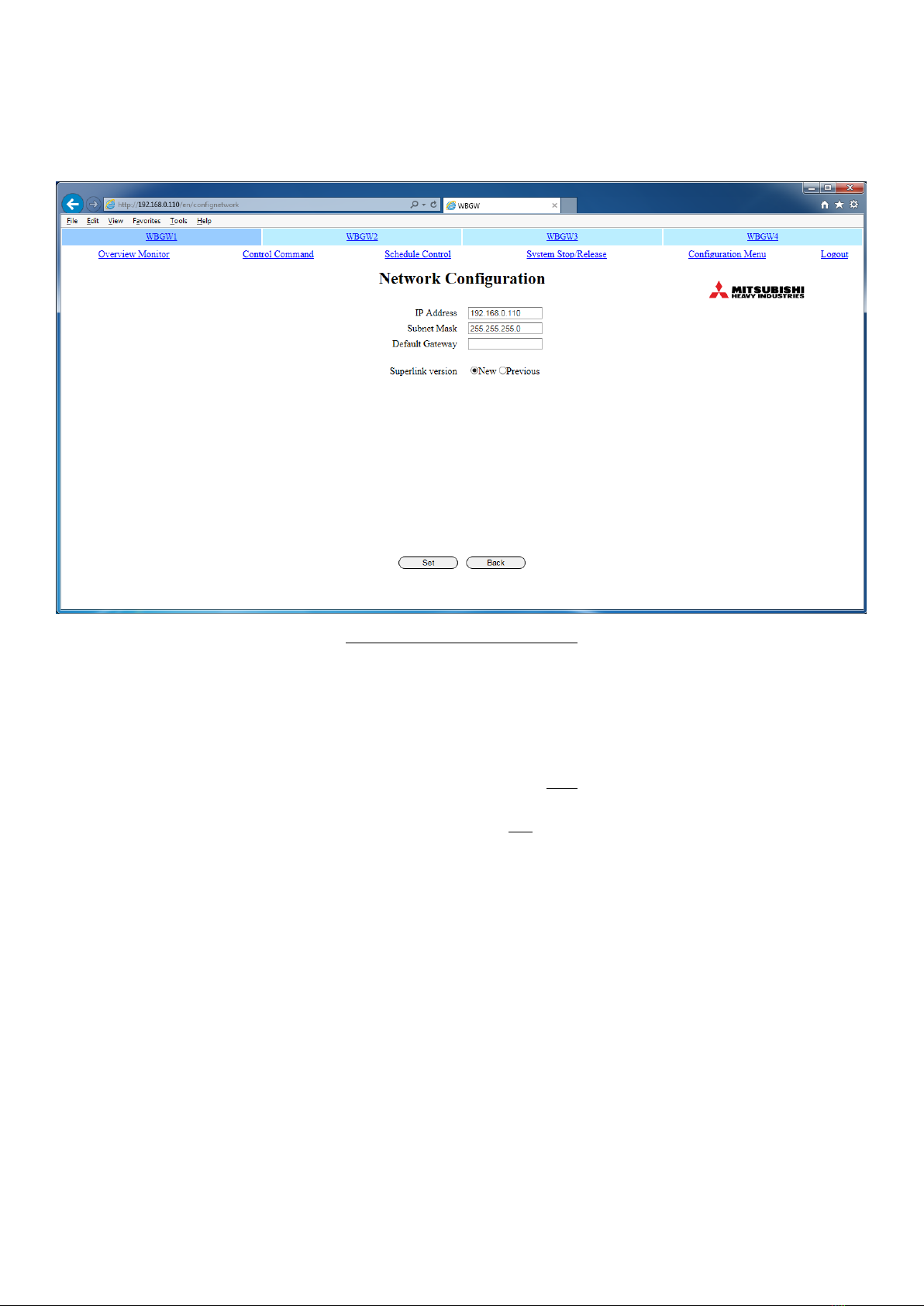
2.3 IP Network Configuration ..........................................................................................................................................................................................4
3Superlink setting ...........................................................................................................................................................................................................7
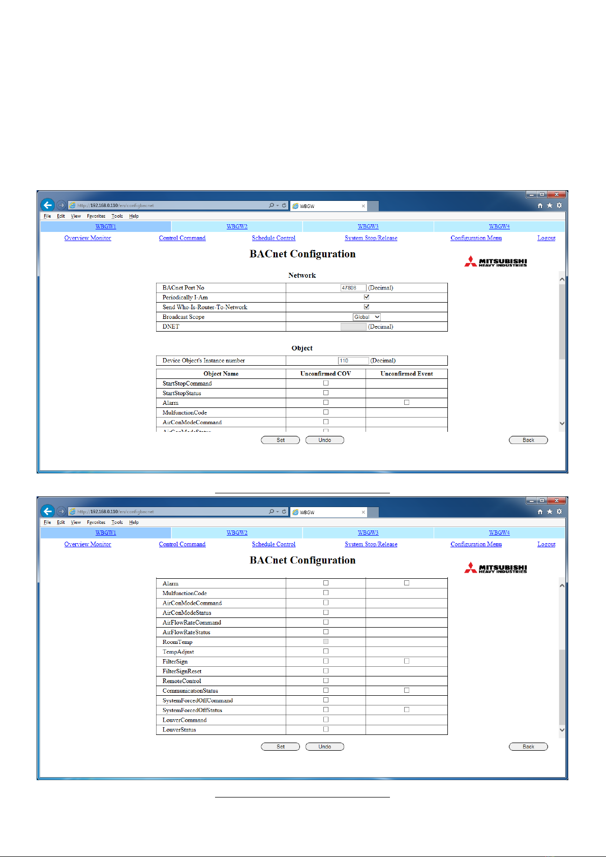
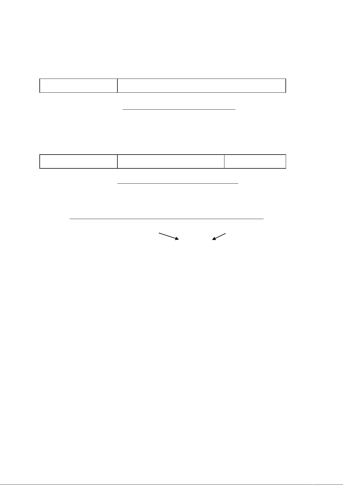
4BACnet Configuration.................................................................................................................................................................................................8
5OBJECT INSTANCE NO. ALLOCATION............................................................................................................................................................9
6BACnet service Startup Configuration..............................................................................................................................................................12
7Air-con CELL Configuration ..................................................................................................................................................................................13
7.1 Air-conditioner Cell Configuration ......................................................................................................................................................................13
7.1.1 SL System Number (SL Sys No) ....................................................................................................................................................................13
7.1.2 Superlink Address (SL Address) .....................................................................................................................................................................13
7.1.3 Air-con Cell Number (CELL No.) ....................................................................................................................................................................17
7.1.4 Air-conditioner Cell name..................................................................................................................................................................................17
7.1.5 Description...............................................................................................................................................................................................................17
7.1.6 Accounting Type....................................................................................................................................................................................................17
7.1.7 Indoor Unit Capacity (Capacity)......................................................................................................................................................................17
7.1.8 Information of Indoor units to connected meter(P1~P8).................................................................................................................17
7.1.9 Meter(P1~P8)......................................................................................................................................................................................................17
7.1.10 Calculation interval..........................................................................................................................................................................................17
7.2 PACinfo256.csv (PACinfo256.xml) File..............................................................................................................................................................18
7.3 Upload / Download of Air-conditioner Cell Configuration File................................................................................................................19
8Date Time Set..............................................................................................................................................................................................................20
9Security Configuration..............................................................................................................................................................................................21
10 Authentication Configuration.................................................................................................................................................................................22
11 Language Configuration............................................................................................................................................................................................23
12 Pulse count & DI status Check screen.............................................................................................................................................................24

SC-WBGW256 Configuration Manual(BACnet) Ver.1.0
Document No. ISTZ17022 June 1, 2017
3
1Scope
This manual is applied to the configuration setting of the " WEB & BACnet Gateway", Model SC-WBGW256.
Any contents of this document may be changed without prior notification.
2Configuration Tool Computer
2.1 Connection Diagram
Fig. 1 shows connection diagram of the Configuration Tool Computer. The following diagram is an example.
The required condition is feasibility of accessing from the Configuration Tool Computer by web browser.
Fig. 1 Configuration Tool Computer Connection Diagram
2.2 Computer
Please check that the computer meets the following specifications.
CPU 500MHz or higher
Memory 512MB or higher
Screen size 1366 x 768 or higher
The combination of the OS and Web browser of the computer is as follows.
Internet Explorer 10
Internet Explorer 11
Windows 7
OK
OK
Windows 8.1
NG
OK
Windows 10
NG
NG
OK: Can be used, NG: Cannot be used
Indoor
Unit IU-2
Indoor
Unit IU-1
Indoor
Unit IU-0
Indoor
Unit IU-2
Indoor
Unit IU-1
Indoor
Unit IU-0
Gateway
(SC- WBGW256)
)
R
R
Building Management System
Host Computer
SUPERLINK No.1 Network
SUPERLINK No.2 Network
R
R
Remote Control
Configuration Tool Computer
must be able to access the
gateway by web browser
Ethernet IP network
Default IP address : 192.168.0.110
Default Subnet mask : 255.255.255.0

SC-WBGW256 Configuration Manual(BACnet) Ver.1.0
Document No. ISTZ17022 June 1, 2017
4
2.3 IP Network Configuration
(0) At the factory, the gateway has been set the default network configuration as follows;
IP address : 192.168.0.110
Subnet mask : 255.255.255.0
Default Gateway : 192.168.0.1
WEB Server URL : http://192.168.0.110/en/
(1) Access web server of the gateway with a web browser of a computer.
WEB Server URL: http://192.168.0.110/en/
In the case the IP address has been changed to be XXX.XXX.XXX.XXX, the URL will be the following;
WEB Server URL : http://XXX.XXX.XXX.XXX/en/
The login screen of the web server will appear as shown in Fig. 2.。
Fig. 2 Login screen
(2) Login to the WEB Server using following UserID and Password to get the main menu screen.
UserID : Admin
Password : 123456
The Overview Monitor screen will appear.
“Configuration Menu” is clicked from the menu at the top of the screen. The Configuration Menu screen will
appear as shown in Fig. 3.

SC-WBGW256 Configuration Manual(BACnet) Ver.1.0
Document No. ISTZ17022 June 1, 2017
5
Fig. 3 Configuration Menu screen

SC-WBGW256 Configuration Manual(BACnet) Ver.1.0
Document No. ISTZ17022 June 1, 2017
6
(3) To get the IP Network Configuration screen, In the Basic Configuration Menu screen in the Configuration Menu,
click “Network Configuration”.
Fig. 4 shows the Network Configuration screen.
Fig. 4 Network Configuration screen
(4) Fill in each field to be changed and click set button. After confirmation, the gateway will be rebooted automatically.
Attention:
・IP address 0.*.*.*, 127.*.*.*, 224.*.*.* to 255.*.*.*
can't be used due to reservations.
・Don't input more than a four-digit number for each octet.
Ex: Correct:192.8.100.110 Incorrect:192.8.0100.110
・Subnet mask must contain only binary bit"1" from left side.
Ex: Correct:255.255.255.0 Incorrect:192.255.255.0
(5) After the gateway restarts, the gateway will work as the new configuration as follows;
IP address : XXX.XXX.XXX.XXX
Subnet mask : YYY.YYY.YYY.YYY
Default Gateway : ZZZ.ZZZ.ZZZ.ZZZ
WEB Server URL : http://XXX.XXX.XXX.XXX/en/

SC-WBGW256 Configuration Manual(BACnet) Ver.1.0
Document No. ISTZ17022 June 1, 2017
7
(6) You can set the Network Configuration (IP address, the subnet mask and default Gateway), Security
Configuration , login ID setting (user ID and password) to the factory default status by the following procedure.
1. Connect the DI3 and COM terminals with the harness and turn on the power.
2. Turn the power off after 5 minutes, disconnect the harness, then turn on the power again.
Be sure to remove the harness and then turn on the power again.
3Superlink setting
In the Basic Configuration Menu screen in the Configuration Menu, click “Network Configuration”.
Set the Superlink communication system setting according to the situation of the site.
Gateway
Harness

SC-WBGW256 Configuration Manual(BACnet) Ver.1.0
Document No. ISTZ17022 June 1, 2017
8
4BACnet Configuration
BACnet configuration such as the Device Instance No., BACnet Port No., or etc. can be changed.
(1) In the BACnet Configuration Menu screen in the Configuration Menu screen, click the “BACnet Configuration”.
The BACnet Configuration screen will appear as shown in Fig. 5 and 6.
(2) To change configuration, enter fields and check boxes. The indoor temperature COV is displayed on the screen,
but can not be specified.
(3) Press Set button to reflect the setting.
Fig. 5 BACnet Configuration screen (1/2)
Fig. 6 BACnet Configuration screen (2/2)

SC-WBGW256 Configuration Manual(BACnet) Ver.1.0
Document No. ISTZ17022 June 1, 2017
9
5OBJECT INSTANCE NO. ALLOCATION
The BACnet standard defines the format of the BACnet Object Identifier as shown in the following diagram. That is,
the 32 bits of the BACnet Object Identifier consists of the higher 10 bits of the BACnet Object Type and the lower 22
bits of the Instance No.
Fig. 7 Format of the BACnet Object Identifier
In this gateway, the 22 bits of the Instance No. shown above are divided into the higher 14 bits and the lower 8bits
as corresponding with the Air-con CELL No. and its Object Member No. as shown in the following diagram. This
structure comes from the concept that each Air-con CELL has a number of Object Members.
Fig. 8 Format of the Instance No. in this gateway
For example, the Instance No. of the Mode command Object(Member No. is 5) of the Air-con CELL No.010 is to be
defined as follows.
Air-con CELL No. Object Member No.
Meaning CELL No. = 010 Object Member No. = 5
Bits of CELL & Member 00000000001010 00000101
Instance No. bit string 00000000001010 00000101 = X’0A05’= 2565
Calculation method 10 x 256 + 5 = 2565
In the case of the System Stop command Object which is only one for this gateway, the Instance No. of the System
Stop command object is defined so as to be the Object Member No.21 of the Air-con CELL No.000.
BACnet Object Type
Air-con CELL No.
Object Member No.
31
22
21
8
7
0
BACnet Object Type
Instance No.
31
22
21
0

SC-WBGW256 Configuration Manual(BACnet) Ver.1.0
Document No. ISTZ17022 June 1, 2017
10
Object ID Allocation (1/2)
A
I
R
・
C
O
N
C
E
L
N
O
.
FunctionMember
M
e
m
b
e
r
C
o
d
e
ObjectName
Object
Type
Instance
Number
ObjectIdentifier
N
A
M
E
C
O
D
E
D
E
C
I
M
A
L
H
e
x
a
d
e
c
i
m
a
l
Decimal
Hexadecimal
0
0
0
On/Off command
1
StartStopCommand_000
BO
4
1
X '000001'
16777217
X '01000001'
On/Off status
2
StartStopStatus_000
BI
3
2
X '000002'
12582914
X '00C00002'
Alarm status
3
Alarm_000
BI
3
3
X '000003'
12582915
X '00C00003'
Error Code
4
MulfunctionCode_000
MI
13
4
X '000004'
54525956
X '03400004'
Mode command
5
AirConModeCommand_000
MO
14
5
X '000005'
58720261
X '03800005'
Mode status
6
AirConModeStatus_000
MI
13
6
X '000006'
54525958
X '03400006'
Fan Speed command
7
AirFlowRateCommand_000
MO
14
7
X '000007'
58720263
X '03800007'
Fan Speed status
8
AirFlowRateStatus_000
MI
13
8
X '000008'
54525960
X '03400008'
Room Temperature
9
RoomTemp_000
AI
0
9
X '000009'
9
X '00000009'
Set Temperatuer
command
10
TempAdjust_000
AV
2
10
X '00000A'
8388618
X '0080000A'
Filter Sign status
11
FilterSign_000
BI
3
11
X '00000B'
12582923
X '00C0000B'
Filter Sign Reset
command
12
FilterSignReset_000
BV
5
12
X '00000C'
20971532
X '0140000C'
Remocon Lock/Unlock
command
13
RemoteControl_000
BV
5
13
X '00000D'
20971533
X '0140000D'
Gasmeter
18
Gasmeter_000
AC
23
18
X '000012'
96469010
X '05C00012'
Wattmeter
19
Wattmeter_000
AC
23
19
X '000013'
96469011
X '05C00013'
Communication status
20
CommunicationStatus_000
BI
3
20
X '000014'
12582932
X '00C00014'
SystemForcedOff
command
21
SystemForcedOff
BV
5
21
X '000015'
20971541
X '01400015'
NonDivisionGasmeter
22
NonDivisionGasmeter
AC
23
22
X '000016'
96469014
X '05C00016'
NonDivisionWattmeter
23
NonDivisionWattmeter
AC
23
23
X '000017'
96469015
X '05C00017'
Louver command
24
AirLouverCommand_000
MO
14
24
X '000018'
58720280
X '03800018'
Louver status
25
AirLouverStatus_000
MI
13
25
X '000019'
54525977
X '03400019'
SystemForcedOff status
26
SystemForcedOffStatus
BI
3
26
X '00001A'
12582938
X '00C0001A'

SC-WBGW256 Configuration Manual(BACnet) Ver.1.0
Document No. ISTZ17022 June 1, 2017
11
Object ID Allocation (2/2)
A
I
R
・
C
O
N
C
E
L
N
O
.
FunctionMember
M
e
m
b
e
r
C
o
d
e
ObjectName
Object
Type
Instance
Number
ObjectIdentifier
N
A
M
E
C
O
D
E
D
E
C
I
M
A
L
H
E
X
A
D
E
C
I
M
A
L
Decimal
Hexadecimal
0
0
1
On/Off command
1
StartStopCommand_001
BO
4
257
X '000101'
16777473
X '01000101'
On/Off status
2
StartStopStatus_001
BI
3
258
X '000102'
12583170
X '00C00102'
Alarm status
3
Alarm_001
BI
3
259
X '000103'
12583171
X '00C00103'
Error Code
4
MulfunctionCode_001
MI
13
260
X '000104'
54526212
X '03400104'
Mode command
5
AirConModeCommand_001
MO
14
261
X '000105'
58720517
X '03800105'
Mode status
6
AirConModeStatus_001
MI
13
262
X '000106'
54526214
X '03400106'
Fan Speed command
7
AirFlowRateCommand_001
MO
14
263
X '000107'
58720519
X '03800107'
Fan Speed status
8
AirFlowRateStatus_001
MI
13
264
X '000108'
54526216
X '03400108'
Room Temperature
9
RoomTemp_001
AI
0
265
X '000109'
265
X '00000109'
Set Temperatuer
command
10
TempAdjust_001
AV
2
266
X '00010A'
8388874
X '0080010A'
Filter Sign status
11
FilterSign_001
BI
3
267
X '00010B'
12583179
X '00C0010B'
Filter Sign Reset
command
12
FilterSignReset_001
BV
5
268
X '00010C'
20971788
X '0140010C'
Remocon Lock/Unlock
command
13
RemoteControl_001
BV
5
269
X '00010D'
20971789
X '0140010D'
Gasmeter
18
Gasmeter_001
AC
23
274
X '000112'
96469266
X '05C00112'
Wattmeter
19
Wattmeter_001
AC
23
275
X '000113'
96469267
X '05C00113'
Communication status
20
CommunicationStatus_001
BI
3
276
X '000114'
12583188
X '00C00114'
Louver command
24
AirLouverCommand_001
MO
14
280
X '000118'
58720536
X '03800118'
Louver status
25
AirLouverStatus_001
MI
13
281
X '000119'
54526233
X '03400119'
Instance Number Allocation Rule
Object_Identifier = ObjectType * X'400000' + InstanceNumber(Hex)
= ObjectType * 4194304 + InstanceNumber(Dec)
InstanceNumber = Cell * X'100' + Member(Hex)
= Cell * 256 + Member(Dec)
BACnet standard
ObjectType
(10bits)
InstanceNumber
(22bits)
Air-Con Cell No
(14bits)
Member
(8 ビット)
Gateway's definition
31
22
21
0

SC-WBGW256 Configuration Manual(BACnet) Ver.1.0
Document No. ISTZ17022 June 1, 2017
12
6BACnet service Startup Configuration
BACnet configuration such as the BACnet transmission start delay can be selected.
About 1 minute later, BACnet transmission starts (Factory setting) or about 3 minute later, BACnet transmission starts
(select the check box) can be selected.
(1) In the BACnet Configuration Menu screen in the Configuration Menu screen, click the “BACnet service Startup
Configuration”.
The BACnet service Startup Configuration screen will appear as shown in Fig. 9.
(2) To set startup delay, Select the check box and click the Set button. After confirmation, the gateway will be rebooted
automatically.
(3) After the gateway restarts, the gateway will work as the new configuration.
Fig. 9 BACnet service Startup Configuration screen

SC-WBGW256 Configuration Manual(BACnet) Ver.1.0
Document No. ISTZ17022 June 1, 2017
13
7Air-con CELL Configuration
Each BACnet objects are linked to a logical unit named “Air-con Cell”. The Air-con Cell configuration, that is the
relationship between the Superlink address and the Cell No., can be set by accessing the WEB Server embedded in the
gateway.
7.1 Air-conditioner Cell Configuration
At the factory, all the 256 Cells from Cell000 to Cell255 have been set as the default setting. The default setting
should be changed so as to match the actual Superlink address allocation at the site.
(1) To get the Air-conditioner Cell Configuration, click the “Air-conditioner Cell Configuration” in the Basic
Configuration Menu screen in the Configuration Menu screen. The Air-conditioner Cell Configuration screen will
appear as shown in Fig. 10.
(2) Using the pull-down menu, set a Cell No. for which each Air-conditioner belongs. To see all the rows, use the
scroll bar at the right side.
(3) Click the "Set" button to activate the new setting.
Fig. 10 Air-conditioner Cell Configuration screen
7.1.1 SL System Number (SL Sys No)
Two SL system numbers for the gateway are written as S1 and S2.
7.1.2 Superlink Address (SL Address)
The SL Address of an indoor unit is written as U000~U127.
SL system number and SL Address are shown in ascending order. For Prev. SL, use U000~U047.

SC-WBGW256 Configuration Manual(BACnet) Ver.1.0
Document No. ISTZ17022 June 1, 2017
14
Table.1 The Cell configuration at the factory (1/3)
Superlink Address
S1
S2
U000
C000
C128
U001
C001
C129
U002
C002
C130
U003
C003
C131
U004
C004
C132
U005
C005
C133
U006
C006
C134
U007
C007
C135
U008
C008
C136
U009
C009
C137
U010
C010
C138
U011
C011
C139
U012
C012
C140
U013
C013
C141
U014
C014
C142
U015
C015
C143
U016
C016
C144
U017
C017
C145
U018
C018
C146
U019
C019
C147
U020
C020
C148
U021
C021
C149
U022
C022
C150
U023
C023
C151
U024
C024
C152
U025
C025
C153
U026
C026
C154
U027
C027
C155
U028
C028
C156
U029
C029
C157
U030
C030
C158
U031
C031
C159
U032
C032
C160
U033
C033
C161
U034
C034
C162
U035
C035
C163
U036
C036
C164
U037
C037
C165
U038
C038
C166
U039
C039
C167
U040
C040
C168
U041
C041
C169
U042
C042
C170
U043
C043
C171
U044
C044
C172

SC-WBGW256 Configuration Manual(BACnet) Ver.1.0
Document No. ISTZ17022 June 1, 2017
15
Table.2 The Cell configuration at the factory (2/3)
Superlink Address
S1
S2
U045
C045
C173
U046
C046
C174
U047
C047
C175
U048
C048
C176
U049
C049
C177
U050
C050
C178
U051
C051
C179
U052
C052
C180
U053
C053
C181
U054
C054
C182
U055
C055
C183
U056
C056
C184
U057
C057
C185
U058
C058
C186
U059
C059
C187
U060
C060
C188
U061
C061
C189
U062
C062
C190
U063
C063
C191
U064
C064
C192
U065
C065
C193
U066
C066
C194
U067
C067
C195
U068
C068
C196
U069
C069
C197
U070
C070
C198
U071
C071
C199
U072
C072
C200
U073
C073
C201
U074
C074
C202
U075
C075
C203
U076
C076
C204
U077
C077
C205
U078
C078
C206
U079
C079
C207
U080
C080
C208
U081
C081
C209
U082
C082
C210
U083
C083
C211
U084
C084
C212
U085
C085
C213
U086
C086
C214
U087
C087
C215
U088
C088
C216
U089
C089
C217

SC-WBGW256 Configuration Manual(BACnet) Ver.1.0
Document No. ISTZ17022 June 1, 2017
16
Table.3 The Cell configuration at the factory (3/3)
Superlink Address
S1
S2
U090
C090
C218
U091
C091
C219
U092
C092
C220
U093
C093
C221
U094
C094
C222
U095
C095
C223
U096
C096
C224
U097
C097
C225
U098
C098
C226
U099
C099
C227
U100
C100
C228
U101
C101
C229
U102
C102
C230
U103
C103
C231
U104
C104
C232
U105
C105
C233
U106
C106
C234
U107
C107
C235
U108
C108
C236
U109
C109
C237
U110
C110
C238
U111
C111
C239
U112
C112
C240
U113
C113
C241
U114
C114
C242
U115
C115
C243
U116
C116
C244
U117
C117
C245
U118
C118
C246
U119
C119
C247
U120
C120
C248
U121
C121
C249
U122
C122
C250
U123
C123
C251
U124
C124
C252
U125
C125
C253
U126
C126
C254
U127
C127
C255

SC-WBGW256 Configuration Manual(BACnet) Ver.1.0
Document No. ISTZ17022 June 1, 2017
17
7.1.3 Air-con Cell Number (CELL No.)
The gateway performs monitoring and control by the cell number.
The cell numbers C000~C255 are assigned to the indoor units specified by the SL system number and SL
Address. Attach a cell number to the indoor unit connected to the SUPERLINK.
It is not necessary to attach a cell number to indoor units that are not connected.
Cell number C000~C255 can be freely assigned to the indoor units. Assign cell numbers to the desired
display order in the Overview Monitor screen.
Moreover, a cell number can set up the indoor unit remote control group. When two or more indoor units are
specified as a remote control group, attach the same cell number to these indoor units to define the group.
Maximum number of the indoor units that form a group is 16. In case of groups, only the indoor unit having
the smallest SL system number or SL address (SL system number being the priority) will be assigned the
“Air-con Cell Name” and “Description” explained in the following clause.
7.1.4 Air-conditioner Cell name
Assign an understandable name to a particular cell number. The length of the character string can be up to 16
characters.
7.1.5 Description
A description more detailed than the cell name can be assigned to a cell number. The length of the character
string can be up to 64 characters. Leave it blank in case recording a detailed description is not necessary.
7.1.6 Accounting Type
Choose from the following the calculating method for the indoor unit.
Type
Calculating Method
MULTI1
Calculating according to the amount of refrigerant flow.
Applicable to KX Series.
MULTI2
Calculating according to the thermo ON/OFF.
Applicable to KX Series.
RUN/STOP
Calculating according to the unit operating time.
Applicable to Multi-indoor unit PAC, Single PAC, PAC for equipment
(with I/F) and Superlink Adapter.
・Select same type for same meter.
・When you select MULTI1 or MULTI2, fan mode units are out of calculation.
To calculate the fan mode units, please select RUN/STOP.
7.1.7 Indoor Unit Capacity (Capacity)
Choose the nominal capacity (Cooling capacity) of the indoor unit.
(0.0/1.5/2.0/2.2//・・・//50.0/56.0/84.0//・・・//224.0 kW)
7.1.8 Information of Indoor units to connected meter(P1~P8)
Set to check box for “v”, the connected meter (P1 to P8) for each indoor unit. The meter, is possible to set
more than one meter.
7.1.9 Meter(P1~P8)
Choose the type of meter (GAS/WATT). Choose blank for not connect the meter terminals.
Choose the meter’s 1 pulse per unit volume (0 - 300). The gas meter’s unit is ” m3”, the electric meter’s unit is
“kWh”.
7.1.10 Calculation interval
Choose (1 / 4 / 8 / 12 or 24 hours) for calculation interval. Run the calculation to specify hourly to starting
from 00: 00. If you choose 8 hours, it calculates at 00: 00, 08: 00, 16: 00.

SC-WBGW256 Configuration Manual(BACnet) Ver.1.0
Document No. ISTZ17022 June 1, 2017
18
7.2 PACinfo256.csv (PACinfo256.xml) File
PACinfo256.csv and PACinfo256.xml are exclusive to the gateway.
The setting information in the Air-con Cell Configuration screen can be downloaded from the Air-conditioner Cell
Configuration File Upload/Download screen and the file can be saved to the computer. This file is called
PACinfo256.csv or PACinfo256.xml. Aside from being a backup file, PACinfo256.csv or PACinfo256.xml can also be
edited using Notepad or EXCEL applications. Edited PACinfo256.csv or PACinfo256.xml can be uploaded from the
Air-conditioner Cell Configuration File screen and can be set as the cell setting.
When opening PACinfo256.csv file with a text editor, it will be displayed as follows.
Fig. 11 PACinfo256.csv file opened using text editor (example)
The CSV file is stored where a comma separates each item. The first line expresses the title of each item to show
the order of the items (Air-con Cell Number(CELL_NO), Description(PLACE), Air-conditioner Cell Name(PLACE_
SHORT), SL System No.(SL_LINE), SL Address(SL_ADDRESS), Accounting Type(KAKIN_TYPE), Capacity(ABILITY),
Information of Indoor units to connected meter(P1), P1 Type(T1), P1 Pulse Constant(C1),・・・,P8 Type(T8), P8
Pulse Constant(C8), Calculation .Interval(INTERVAL)). The second and succeeding lines show the data from the
Air-conditioner Cell Configuration File screen. Since each item is separated by commas, a comma cannot be
inputted into the contents of each item. If a comma is inputted, the gateway will not be able to recognize it
correctly.
Attention:
Do not use ", & < > " '" for each input item. If you enter these characters and upload the file, the screen may not
be displayed correctly. In this case, turn off the power of this gateway, turn on the power again, and upload the file
without ", & < > " '".
CELL_NO,PLACE,PLACE_SHORT,SL_LINE,SL_ADDRESS,KAKIN_TYPE,ABILITY,P1,T1,C1,P2,T2,C2,P3,T3,C3,P4,T4,C4,P5,T5,C5
,P6,T6,C6,P7,T7,C7,P8,T8,C8,INTERVAL
C000,This room is Cell 000.,Room 000,S1,U000,RUN/STOP,10,OFF,,,OFF,,,OFF,,,OFF,,,OFF,,,OFF,,,OFF,,,OFF,,,1
C001,This room is Cell 001.,Room 001,S1,U001,RUN/STOP,20,OFF,,,OFF,,,OFF,,,OFF,,,OFF,,,OFF,,,OFF,,,OFF,,,1
C001,This room is Cell 001.,Room 001,S1,U002,RUN/STOP,10,OFF,,,OFF,,,OFF,,,OFF,,,OFF,,,OFF,,,OFF,,,OFF,,,1
C001,This room is Cell 001.,Room 001,S1,U003,RUN/STOP,10,OFF,,,OFF,,,OFF,,,OFF,,,OFF,,,OFF,,,OFF,,,OFF,,,1
C001,This room is Cell 001.,Room 001,S1,U004,RUN/STOP,0,OFF,,,OFF,,,OFF,,,OFF,,,OFF,,,OFF,,,OFF,,,OFF,,,1
lines
1
2
3
4
5
6

SC-WBGW256 Configuration Manual(BACnet) Ver.1.0
Document No. ISTZ17022 June 1, 2017
19
7.3 Upload / Download of Air-conditioner Cell Configuration File
The Air-conditioner Cell Configuration file can be uploaded and downloaded as a CSV format.
(1) To get the Air-conditioner Cell Configuration File Upload/Download screen, click the “Air-conditioner Cell
Configuration File Upload/Download” in the Basic Configuration Menu screen in the Configuration Menu screen.
The Air-conditioner Cell Configuration File Upload/Download screen will appear as shown in Fig. 12.
(2) Click the "Download" button to download Air-conditioner Cell Configuration file and follow the Windows guidance.
(3) Click the " Browse" button to upload Air-conditioner Cell Configuration file and follow the Windows guidance.
Fig. 12 Air-conditioner Cell Configuration File Upload/Download screen

SC-WBGW256 Configuration Manual(BACnet) Ver.1.0
Document No. ISTZ17022 June 1, 2017
20
8Date Time Set
(1) To get the Date and Time Configuration screen, click the “Date and Time Configuration” in the Basic Configuration
Menu screen in the Configuration Menu screen. Fig.13 shows the Date and Time Configuration screen.
(2) Select, or fill in the fields to set date and time, and click the "Set" button.
The System time of the gateway will be set to the date and time.
Fig. 13 Date and Time Configuration screen
Note: When a BACnet device, which sends TimeSynchronization Service periodically, is connected to the network,
SC-WBGW256 adjusts date and time itself automatically.
Other manuals for Superlink SC-WBGW256
2
Table of contents
Other Mitsubishi Heavy Industries Gateway manuals
Popular Gateway manuals by other brands

ZyXEL Communications
ZyXEL Communications USG310 Specifications

Pathport
Pathport PWPP DIN P4 manual

turck
turck BL67-4DI-P user manual

Lucent Technologies
Lucent Technologies PacketStar PSAX Series quick start guide

Rainforest Automation
Rainforest Automation EAGLE quick start guide

RTA
RTA 460ETCWI-NNA1 Product user guide