Mitsubishi MOTORS M.U.T.-III User manual

MITSUBISHI MOTORS
Multi Use Tester III
MUT-
III Owner’s Manual
< Ver. 3.0 >
H
He
ea
ar
rt
t-
-B
Be
ea
at
t
M
Mo
ot
to
or
rs
s
MITSUBISHI MOTORS

Foreword
This manual explains MUT-III: functions, operating procedures, and other related information.
By reading this manual you will obtain a basic understanding of MUT-III and Vehicle Communication
Interface (hereafter abbreviated as V.C.I.) functions and methods of operation. Because there are
differences in MUT-III methods of operation due to the vehicle electronic control system, be sure to
read this manual and Online Help prior to operation.
This manual was written based on the December 2004 version of the MUT-III system.
Please note that the information herein may not always agree with your version of the MUT-III
system due to system specification changes and version upgrades.
Please take good care of this manual along with your MUT-III product.
MUT-III User's Manual

Table of Contents
Chapter 1 Product Overview........................................................................................ 1
1-1. Precautions...............................................................................................................................1
1-2. V.C.I. Outline Drawing and Component Names........................................................................2
1-3. MUT-III Components Explanations ...........................................................................................3
1-4. Harness Connection Method ....................................................................................................5
1-5. Combination Chart of Harness and Vehicle ..............................................................................6
Chapter 2 MUT-III Functions ........................................................................................ 8
2-1. Basic Functions ........................................................................................................................8
2-2. V.C.I. Functions ........................................................................................................................9
Chapter 3 Operating MUT-III....................................................................................... 10
3-1. Starting and Shutting the MUT-III System ..............................................................................10
3-2. Screen Explanations...............................................................................................................12
3-3. Basic Flow to Start Diagnosis .................................................................................................14
3-4. Option Settings .......................................................................................................................16
3-5. Useful Functions.....................................................................................................................17
Chapter 4 Diagnosis Function ................................................................................... 18
4-1. Diagnostic Code .....................................................................................................................18
4-2. Data List (Service Data monitor).............................................................................................19
4-3. Actuator Test...........................................................................................................................22
Chapter 5 Special Function (Calibration & Setting) ................................................. 26
5-1. Steering Angle Sensor Calibration ..........................................................................................26
5-2. Lateral G sensor Calibration ...................................................................................................28
Chapter 6 Drive Recorder........................................................................................... 29
6-1. How to Record the Data .........................................................................................................29
6-2. Recorded Data Handling ........................................................................................................41
6-3. Display and Analysis of the Recorded Data............................................................................46
Chapter 7 SWS Monitor .............................................................................................. 52
7-1. SWS Monitor Operation..........................................................................................................52
Chapter 8 Coding Function........................................................................................ 61
8-1. VIN Writing Function...............................................................................................................61
Chapter 9 CAN Bus Diagnosis................................................................................... 63
9-1. Diagnosing the CAN Bus ........................................................................................................63
MUT-III User's Manual

Chapter 10 ECU Reprogramming .............................................................................. 64
10-1. Process Flow Chart ..............................................................................................................64
10-2. Equipments...........................................................................................................................65
10-3. Data preparation on PC from Update CD-ROM....................................................................66
10-4. Reprogramming Operation ( VCI alone )............................................................................67
10-5. Reprogramming Operation ( VCI - PC connected )............................................................74
10-6. Reprogramming by CAN communication (for Colt:Z30#)......................................................77
10-7. Troubleshooting of Reprogramming......................................................................................79
Chapter 11 Measurement Functions ......................................................................... 82
11-1. Injector-Type Fuel Consumption Measurement ....................................................................82
11-2. Fuel pressure, Voltage, Ohmmeter, Oscilloscope .................................................................84
Chapter 12 Troubleshooting Procedures.................................................................. 87
12-1. Individual Troubleshooting Procedures.................................................................................87
Chapter 13 Maintenance and Support....................................................................... 89
13-1. Maintenance .........................................................................................................................89
13-2. Support .................................................................................................................................89
Chapter 14 Reference Material .................................................................................. 90
14-1. V.C.I. Electrical Properties ....................................................................................................90
Appendix ..................................................................................................................... 91
<< Terminology >> .........................................................................................................................91
<< Screen Button Explanations >> ................................................................................................93

For Your Safety
To ensure proper use of this product and prevent personal injury and property damage, various graphic
displays are used in the user’s manual. The graphic displays and respective meanings are described
below.
Warning
Warning messages alert you to a procedure or practice
which, if not followed correctly, could lead to death or serious
injury.
Caution
Caution messages alert you to a procedure or practice which, if
not followed correctly, could lead to serious injury and/or
property damage.
Icon
Examples
The symbol alerts you to a prohibited action.
The symbol alerts you to an action that must be enforced.
Drivers should not operate the unit while driving.
• Operating the unit while driving may result in
a traffic accident.
Do not plug in or unplug the power AC adapter with
wet hands.
• Doing so results in the risk of electric shock.
When using the cigarette lighter plug to supply
power to the V.C.I. unit, be sure the power
voltage supplied is DC32V or less.
• Applying a voltage greater than DC32V results
in the risk of fire.
• MUT-III as provided to dealers includes 12V
accessory / cigarette lighter plug adapter to
power MUT-III during extended test drives.
Maximum voltage the V.C.I. can withstand is 40V.
Do not use the V.C.I. on systems greater than the
32-volt system mentioned previously.
• Violating this requirement results in the risk of a
ground fault, damage and/or electric shock.
For Your Safety
Warning

The V.C.I. screen is liquid crystal display or
LCD. In the unlikely event that the display
breaks due to impact, do not let your skin
come in contact with the LCD fluid.
• If your skin comes in contact with the LCD
fluid, wash your skin thoroughly with water.
If skin rash or abnormality occurs seek
medical attention from a doctor.
Do not use the unit if the power AC adapter plug
or cord is damaged or plugging into the outlet is
loose.
• Use under such conditions may result in
electric shock, an electric short and/or fire.
Be sure to hold the harness connector when
disconnecting from the vehicle. Do not
disconnect the harness by pulling on the cord.
• Pulling the cord rather than the connector
may result in damage to the lead wire inside
the cord, thereby causing a short and possibly
starting a fire.
Unplug the power AC adapter from the outlet
when the unit is not in use.
• Failure to do so may result in injury, burns,
electric shock caused by insulation
deterioration, or fire due to a short circuit.
When the harness is connected to the V.C.I., be sure to check the top and bottom of the
connector and connect the harness perpendicularly to the connector of the V.C.I.
Connecting at an angle may result in bending of the pins of the connector.
Check for the secure connection of the harness before tightening of the screw locks.
• The bent pin may contact the connector case, thereby causing an electric short which
leads to damage to the V.C.I.
Warning
Warning
For Your Safety

Please Note
Do not expose the PC or V.C.I. to direct sunlight or high temperatures, or leave the unit in
sun-heated cars. Such action may result in system failure.
Store the PC and V.C.I. in a dry environment at room temperatures.
Moving the PC and V.C.I. to a location with a very different temperature and humidity than that of
the previous location may result in external or internal condensation. Caution is required.
Protect the PC and V.C.I. from exposure to elements such as rain, dirt, dust, food and liquids.
Be careful when handling the PC and V.C.I. Dropping the units may result in damage.
Do not expose either unit to engine oil, gasoline, antifreeze or battery acid. Also, do not clean the
PC or V.C.I. case using solutions such as thinner or benzene. Doing so may result in deterioration
of the case surface.
Prior to connecting the MUT-III main harness between the V.C.I. and vehicle, turn the IG switch to
OFF.
• Connecting the V.C.I. harness with the IG switch ON may damage the V.C.I. programming.
Use only the power AC adapter included with the PC (or approved replacement), power cigarette
plug, other probes, main harness and other cables.
• Use of unspecified parts may result in damage or malfunction due to excess voltage or
insufficient contact.
The LCD display of this unit turns off when the supplied voltage is less the DC 8V. This is not an
error.
The power supplied should be from 8VDC to 32VDC.
Keep all V.C.I. connectors and openings away from dirt and static electricity. Exposure to dirt and
static electricity may result in malfunction and damage.
For Your Safety

1
Chapter 1 Product Overview
1-1. Precautions
Service Work Precautions
• Be sure to follow all basic service work precautions when using MUT-III during vehicle
inspection and service work.
• For detailed information regarding service work precautions, refer to the service instruction
manual of each vehicle.
Work Precautions
• When performing vehicle inspection work at the work site with the engine running, either use an
exhaust gas discharger or ventilate the area sufficiently.
• When working on a vehicle, be sure to apply the parking brake and set wheel chocks in place to
prevent the car from moving.
Driving Precautions
• If you wish to use MUT-III while driving the target vehicle, first verify that all parts are properly
assembled.
• While driving, always have an assistant operate MUT-III.
• Be sure that the MUT-III main harness and other cables will not interfere with driving.
• Install and remove the PC and V.C.I. with the vehicle parked, IG switch OFF.
PC Usage Limitations
Do Not Install Software on the PC
• The MUT-III PC is a special service tool. Do not install any software other than MUT-III software
onto the unit. Installation of other software results in the risk of MUT-III system failure.
• Any unauthorized software will not be supported. Technical support for units with
unauthorized software will be charged additional technical support fees to return the unit to its
authorized state of operation.
• All unauthorized software will be erased with each new upgrade.
Precautions
2
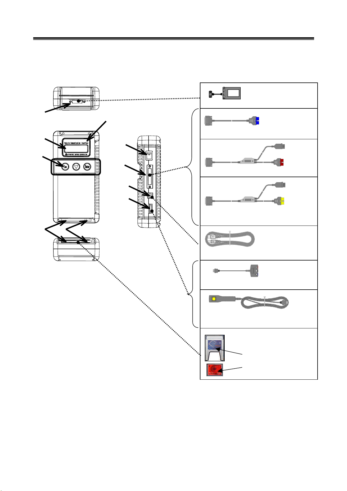
1-2. V.C.I. Outline Drawing and Component Names
The names of the V.C.I. components are indicated in the figure below.
<<Component Names>>
1. I/F cartridge terminal
2. LCD screen
3. Indicator lamp
4. Operation button
(Used with V.C.I. functions)
5. Memory card removal lever
6. Memory card insertion port
7. Power switch
8. Main harness terminal
9. USB terminal
10. Trigger terminal
V.C.I. Outline Drawing and Component Names
Trigger harness (MB991826)
(Not available in US)
CF memory card
&adapter
(MB991853)
(MB991939)
I/F cartrid
g
es
MUT-III main harness A (MB991910)
MUT-III main harness B (MB991911)
USB cable (MB991827)
Measurement adapter (MB991825)
6
1
8
9
10
3
4
5
2 7
MUT-III main harness C (MB991914)
(For US only)

3
1-3. MUT-III Components Explanations
(1) Vehicle Communication Interface (V.C.I.) (MB991824)
A communication interface used to connect the vehicle
ECUs and the PC.
1. When connected with the PC
• Vehicle diagnosis (Interactive fault diagnosis)
• SWS communication & CAN communication support
• Drive recorder
• ECU reprogramming
• Volt, Ohm, measurement
• Fuel pressure measurement (Not available in US)
2. When used with the V.C.I. unit (disconnected from PC)
• Drive recorder
• ECU reprogramming
• Volt, Ohm measurement
• Belt Tension measurement
(2) Memory Card
Stores data for ECU reprogramming, drive recorder, etc.
This is a standard, off-the-shelf memory card. The one
provided (with reprogramming data) is a Compact Flash
memory card (MB991853) inserted into the CF card adapter
(MB991939).
(3) MUT-III Main Harness A (MB991910)
Used when connecting the V.C.I. with vehicles that have
only one 16-pin diagnosis connector.
• Supports fault diagnosis and ECU updating on the
above-described vehicles
• Supports the CAN communication system
(4) MUT-III Main Harness B (MB991911)
Used to connecting V.C.I. with vehicles that have a 16-pin +
12-pin or 16-pin + 13-pin diagnosis connector.
-For models equipped with a 12-pin (or 12-pin + 12-pin)
diagnosis connector, connect the MUT-II adapter harness
(MB991498) to the end of this harness in the same as
MUT-II, and power is supplied from the cigarette lighter
socket.
MUT-III Components Explanations

4
(5) MUT-III Main Harness C (MB991914) (For US only)
Used when connecting the V.C.I. with vehicles that have the
420A engine and F4AC1 transaxle.
(6) USB Cable (MB991827)
Used to connect the PC to the V.C.I.
(7) Trigger Harness (MB991826) (Not available in US)
A harness with a trigger button used to manually insert a
trigger point for data acquisition from the drive recorder
function during data recording.
(8) Measurement Adapter (MB991825)
An adapter used to connect the V.C.I. and measurement
probe for voltmeter and ohmmeter readings.
Or used when outputting Simulated Vehicle Speed with a
vehicle whose diagnosis-connecter cannot receive vehicle
speed signal.
(9) Measurement Test Leads (MB991499)
Test leads used for voltage and / or resistance
measurement.
Test leads MB991499 acquire quality replacement test
leads from Radio Shack or similar electronics stores.
(10) I/F Cartridge
Used to implement special functions that cannot be
implemented with the V.C.I. unit alone. The following I/F
cartridges used with MUT-II can be used with MUT-III as
well:
• SWS I/F cartridge
• Daimler-Chrysler Corporate I/F cartridge
MUT-III Components Explanations
5
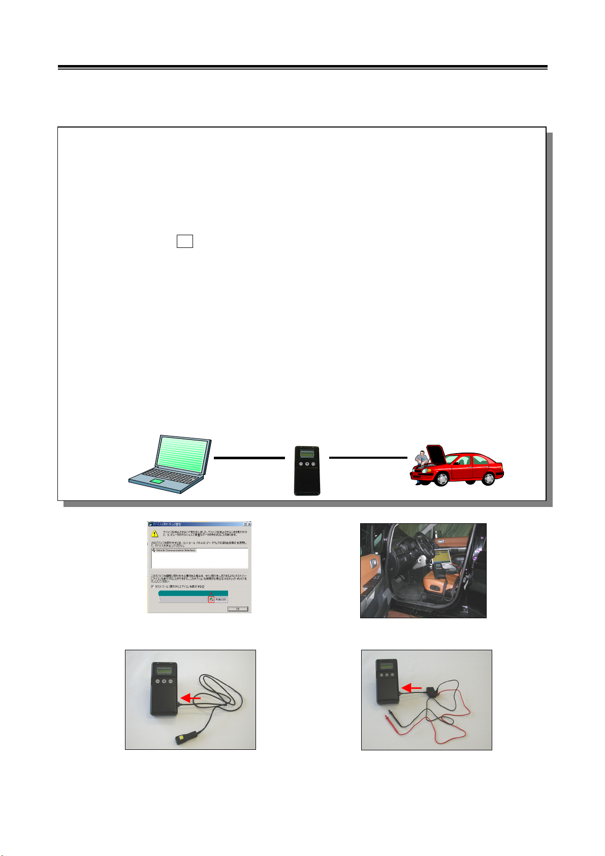
1-4. Harness Connection Method
Harness Connection Method
Recommended harness connection sequence
[1] Start the PC.
[2] While the PC is starting, connect the USB cable to the V.C.I.
[3] After the PC boots to the MUT-III main screen, connect the USB cable to the PC.
Note: Disconnect the USB cable from the V.C.I. after the PC has shut down. However, if the
USB cable is disconnected during use, a warning message indicating device
disconnection such as that shown in Figure 1 appears. Close the message display by
pressing the OK button.
[4] Select the appropriate MUT-III main harness. Connect it to the V.C.I.
[5] Connect the MUT-III main harness to the vehicle diagnosis connector. See Figure 2.
Note: Disconnect the harnesses by performing the above steps in the reverse order.
[6] Turn the V.C.I. power switch ON and verify that the indicator lamp located in the upper right area
of the LCD screen is green.
[7] From the MUT-III system menu, turn the vehicle ignition switch ON and begin the diagnostic
process.
Note: When the version of V.C.I. and the firmware version of V.C.I., which are, mismatch, the
V.C.I. version upgrade process begins. This upgrade typically only occurs once pe
r
MUT-III system upgrade. Normal V.C.I. upgrades take about 1 minute. If a version
upgrade error occurs, restart the V.C.I. by turning V.C.I. power OFF then, while pressing
the Esc button, turn the V.C.I. power switch ON and begin the diagnostic process again.
[5][2][3] [4]
[6] [7]
[1]
<Fig. 1>
Connect the trigger harness to the
V.C.I. trigger terminal.
(Not available in US)
<Connecting the Trigger Harness>
Connect the measurement adapter to the V.C.I.
trigger terminal. Insert the measurement leads to
the adapter. For best results, match the test lead
colors with those on the ada
p
te
r
.
<Connecting the Measurement Adapte
r
and Measurement Probe >
<Fig. 2>

6
1-5. Combination Chart of Harness and Vehicle
Use of the MUT-III main harness A, B or C (US only) is determined by the type of diagnosis
connector installed in the vehicle.
The main harness, indicated with “O”, is used in combination with another harness indicated with
“” depending on the vehicle and work to be performed. ECU update used below means ECU
reprogramming.
01 02 03 04 05
Harness Name
Vehicle
Diagnosis
Connector
MUT-III Main
Harness A
MUT-III Main
Harness B
MUT-III Main
Harness C
Conventional
Vehicle Inspection
Adapter Harness
ECU Update
Adapter Harness
Fault diagnosis O
16Pin ECU update O
Fault diagnosis O
16Pin&12Pin ECU update O
Fault diagnosis O
12Pin ECU update - - - - -
Fault diagnosis O
16Pin&13Pin ECU update O
Fault diagnosis O
Vehicle with
420A Engine and
F4AC1 Transaxle ECU update - - -
Harness Name Illustration
01 MUT-III Main Harness A
MB991910
02 MUT-III Main Harness B
MB991911
03 MUT-III Main Harness C
MB991914
(For US only)
04 Conventional Vehicle Inspection
Adapter Harness (MUT-II adapter harness)
MB991498
05 ECU Update Adapter Harness
MB991855
Combination Chart of Harness and Vehicle
Diagnostic
Function

7
Vehicle diagnostic connector - 16pin type
to 16pin diagnosis connector
Vehicle diagnostic connector - 16pin type + 12 pin type
to 12pin diagnosis connector
to 16pin diagnosis connector
Vehicle diagnostic connector - 12pin type
to 12pin diagnosis connector
to cigarette lighter
Vehicle diagnostic connector - 16pin type + 13 pin type
to 13pin diagnosis connector
to 16pin diagnosis connector
Main harness A
(MB991910)
Main harness B
(MB991911)
Main harness B
(MB991911)
Main harness B
(MB991911)
Conventional Vehicle Inspection Adapter harness
(MUT-II Adapter Harness)
(MB991498)
ECU update
adapter harness
(MB991855)
Combination Chart of Harness and Vehicle

8
Chapter 2 MUT-III Functions
2-1. Basic Functions
Can be used with all vehicle installed electronic control systems (with built-in diagnostic functions)
from model year 1984.
Function Synopsis
DTC readout
Reads various diagnostic codes and displays the codes by name and
number.
Data List
Reads RAM data inside ECU and displays the data in digital and graphic
form. (Available with ECUs that support serial communication only)
Actuator tests
Permits forced operation or shutdown of various types of actuators that is
required for service.
(Available with ECUs that support serial communication only)
Simulated
vehicle speed
Outputs vehicle speed signal to appropriate ECUs facilitating diagnosis
without travel.
Drive Recorder
Permits recording and displaying arbitrary service data that is determined
for an arbitrarily specified time.
Voltmeter
Permits measurement of DC voltage within the range of 0- ±40V using
the voltage measurement function.
Ohmmeter
Permits measurement of resistance within the range of 0-100KΩusing
the resistance measurement function.
SWS Diagnosis Permits SWS diagnosis using the SWS monitor kit (MB991806).
CAN Bus Diagnosis
Identifies CAN bus failures that occur in vehicle that is subject to the
diagnosis and narrows down a cause.
ECU Reprogramming Permits updating programs in ECU for system version upgrade.
Electronic service
information
Displays with Service manual data.
In addition, the system supports interactive fault diagnosis. The Interactive
Diagnosis permits user to use both the scan tool viewing functions and
service manual troubleshooting procedures.
(Not available in US and Australia)
Tension meter
Permits measurement of belt tension using Belt tension meter set
(MB991668).
Fuel pressure meter
Permits measurement of fuel pressure using a pressure gauge set
(MB991637 / MB991981), and displays it on PC. (Not available in US)
Fuel consumption
measurement
Permits more precise measurement of fuel consumption by measuring
injection quantity of fuel injector.
Basic Functions

9
2-2. V.C.I. Functions
<When V.C.I. and PC are connected>
2-2-1. Fault Diagnosis
The system diagnoses faults by receiving instructions from
the PC and communicating with the vehicle-installed ECU.
When the system is connected to the PC, VCI keys are
disabled.
[Start Screen]
*When the USB cable is connected to the system, the
screen illustrated on the left appears.
The screen indicates the flow of signals between the PC (P)
and V.C.I. (V) using “P V” and “P V”.
2-2-2. Fuel Pressure measurement
The system analyzes faults by measuring fuel pressure
using the Pressure gauge set (MB991637 or MB991981).
the pressure gauge for LP: MB991655 or MB991979
for HP: MB991708 or MB992007
The V.C.I. reads the fuel pressure, which is converted into
voltage value by the pressure gauge. Then the system
converts it back to pressure value and displays it as text or
graph on PC screen. (refer to 11-2-1.)
<With the V.C.I. only>
2-2-3. Measurement Function 1: Voltmeter / Ohmmeter
The system reads the voltage/resistance value from the trigger
terminal and displays the value on the V.C.I. LCD screen.
1. Connect the measurement adapter to the V.C.I., connect the
test leads to the adapter.
2. Connect the appropriate main harness to the V.C.I., and then
to the vehicle diagnostic leak connector and turn the V.C.I.
power switch ON.
3. Press button to select Voltmeter or Ohmmeter in the
Main Menu (see the illustration on the left), and press the
button to begin measurement.
Note:
• Permits measurement of DC voltage within the range of 0-
±40V.
• Permits measurement of resistance within the range of
0-100KΩ.
• Permits displaying the value as text or graph on PC screen
by connecting the V.C.I. to PC. (refer to 11-2-2.)
V.C.I. Functions

10
Chapter 3 Operating MUT-III
3-1. Starting and Shutting the MUT-III System
3-1-1. Starting the MUT-III System
[Starting the PC]
1. Please turn on the power of MUT-III PC.
(Refer to the instructions of MUT-III PC for
details.)
[To start up MUT-III System]
2. Double-click the MUT-III icon displayed on the
desktop to start up the system.
Trademarks
• Microsoft®, Windows 2000® and Internet Explorer® are trademarks or registered trademarks of
Microsoft Corporation in the United States and/or other countries.
• Adobe, the Adobe logo, Adobe Acrobat and the Adobe Acrobat logo are trademarks of Adobe
Systems Incorporated.
Starting PC and MUT-III System
[MUT-III icon]

11
3-1-2. Shutting Down the MUT-III System
[Close the MUT-III System]
1. Press button on each diagnostic screen to return to the
STV start menu screen (illustrated on the left).
Then press button on this screen to go to the MUT-III
Start screen.
2. Press Exit button displayed in the lower right portion of
the screen. The MUT-III system will close.
[Shutting down the PC]
3. Click the Windows Start button (lower left portion of the
screen), and select “Shut Down”.
4. Select “Shut down” by pressing button, and press the
OK button.
Shutting Down MUT-III System and PC

12
3-2. Screen Explanations
Screen Explanations
To set option settings, e.g. displaying
language. (refer to 3-4.)
< MUT-III Start Screen >
Starts “Scan Tool Viewe
r
” system.
This manual contains information fo
r
proper operation of this system.
Press this button first to start various
interactive diagnoses.
Exit the MUT-III system.
For detailed operation procedure
(refer to 3-1-2.)
< Start Menu Screen >
-Displaying saved data
(Drive recorder, SWS monitor)
-ECU reprogramming (Chapter 10)
-Measurement Function (Chapter 11)
To diagnose vehicles by selecting
each system (ECU).
e.g.
-Reading diagnostic code
-Actuator test -Drive recorder
For detailed operation procedure,
refer to 3-3-1.
Starts the CAN bus diagnosis.
Refer to Chapter 9.
Starts “Service Manual Viewe
r
”.
For detailed operation procedure,
click the SMV MANUAL bookmark
on the left screen of Adobe Reader.
Shows “MUT-III Owner’s Manual”.
(refer to 3-5-2.)

13
<S
y
stem Selection Screen>
<Dia
g
nostic Screen>
The diagnostic screen displays
three titles in layer format,
informing you what is being
implemented on each system.
The screen does not allow you
to switch systems by selecting
the upper title areas.
Screen Explanations
The system selection screen
allows you to switch between
major system categories by
selecting the tabs located on the
upper part of the screen.
Other manuals for M.U.T.-III
1
Table of contents
Popular Diagnostic Equipment manuals by other brands


Launch
Launch X-431 PAD VI user manual

Launch
Launch X-431 EURO TURBO user manual

Launch
Launch Creader Professional 129i user manual

ACS
ACS AUTOMOTIVE DIAGNOSTIC TOOL instruction manual

MAHA Maschinenbau Haldenwang
MAHA Maschinenbau Haldenwang MBT Series Original operating instructions

Space
Space PFB035 Series NSTRUCTION OPERATION AND MAINTENANCE MANUAL


