Space PFB035 Series Installation guide

User Manual
SPACE s.r.l.
Soc.a socio unico
PFB035 SERIES –PFB040 SERIES
PFB045 SERIES –PFB060 SERIES
SPRT102/4 SERIES –SPRT102/5 SERIES
SPRT102/6 SERIES –SPRT102/7 SERIES
Code M0247 - Ver.1.4
(09/2016)
SPACE s.r.l. –10090 TRANA (TO) Via Sangano, 48
Tel. (+39) 011/ 934 40 300 –Fax (+39) 011/ 933 88 64
BRAKE TESTER –TEST LANE
CONTROL UNIT:
PFC750
PFC800
PFC750/WALL
ROLLER BRAKE TESTERS:
PFB035 SERIES –PFB040 SERIES
PFB045 SERIES –PFB060 SERIES
SPRT102/4 SERIES –SPRT102/5 SERIES
SPRT102/6SERIES –SPRT102/7 SERIES
INSTRUCTION OPERATION
AND MAINTENANCE MANUAL
COMPOSIZIONE
COMPOSITION
ZUSAMMENSETZUNG
COMPOSITION
COMPOSICIÓN
70 pagine (copertine
comprese)
70 pages (including
cover pages)
70 Seiten (inkl.
Deckblätter)
70 pages (pages de la
couverture incluses)
70 páginas (incluidas
las portadas)
68 pagine numerate
68 numbered pages
68 numerierte Seiten
68 pages numérotées
68 páginas numeradas
• Per eventuali chiarimenti interpellare il più vicino rivenditore oppure rivolgersi direttamente a:
• For any further information please contact your local dealer or call:
• Im Zweifelsfall ober bei Rückfragen wenden Sie sich bitte an den nächsten Wiederverkäufer oder direkt an:
• Pour tout renseignement complémentaire s’adresser au revendeur le plus proche ou directement à:
• En caso de dudas, para eventuales aclaraciones, póngase en contacto con el distribuidor más próximo ó diríjase
directamente a:
User Manual
SPACE s.r.l.
Soc.a socio unico
PFB035 SERIES –PFB040 SERIES
PFB045 SERIES –PFB060 SERIES
SPRT102/4 SERIES –SPRT102/5 SERIES
SPRT102/6 SERIES –SPRT102/7 SERIES
Code M0247 - Ver.1.4
(09/2016)
SPACE s.r.l. –10090 TRANA (TO) Via Sangano, 48
Tel. (+39) 011/ 934 40 300 –Fax (+39) 011/ 933 88 64
SIMBOLOGIA UTILIZZATA NEL MANUALE
SYMBOLS USED IN THE MANUAL
IN DER BETRIEBSANLEITUNG VERWENDETE ZEICHEN
SYMBOLES UTILISES DANS LA NOTICE
SIMBOLOGÍA UTILIZADA EN EL MANUAL
SIMBOLI
SYMBOLS
ZEICHEN
SYMBOLES
SÍMBOLOS
VIETATO!
FORBIDDEN!
VERBOTEN
INTERDIT!
PROHIBIDO!
Obbligo!
Operazioni o
interventi da
eseguire
obbligatoriamente
Mandatory!
Operations or jobs
to be performed
compulsorily
Vorschirift
Obligatorisch
auszuführende
Arbeitsvorgänge
oder Eingriffe
Obligation.
Opérations ou
interventions
obligatoires
Obigación.
Operaciones o
intervenciones que
hay que realizar
obligatoriamente
Pericolo!
Prestare particolare
attenzione
Hazard!
Be especially
careful
Gefahr!
Äusserste Vorsicht
ist geboten
Dager!
Faire trés
attention
Peligro!
Prestar especial
atención
Pericolo: scariche
elettriche
Shock hazard
Gefahr! elektrische
Entladungen
Danger
d’électrocution
Peligro de
descargas
eléctricas

User Manual
SPACE s.r.l.
Soc.a socio unico
PFB035 SERIES –PFB040 SERIES
PFB045 SERIES –PFB060 SERIES
SPRT102/4 SERIES –SPRT102/5 SERIES
SPRT102/6 SERIES –SPRT102/7 SERIES
Code M0247 - Ver.1.4
(09/2016)
SPACE s.r.l. –10090 TRANA (TO) Via Sangano, 48
Page 1/68
Tel. (+39) 011/ 934 40 300 –Fax (+39) 011/ 933 88 64
TABLE OF CONTENTS
0. CAUTION .......................................................................................................................3
0.1. Preliminary safety information..........................................................................................3
1. INTENDED USE.............................................................................................................4
2. PERSONNEL TRAINING ...............................................................................................4
2.1. General preventive measures..........................................................................................4
2.2. Indication of outstanding risks..........................................................................................5
2.3. Emergency devices .........................................................................................................5
2.4. Safety devices .................................................................................................................5
2.5. Emergency situations.......................................................................................................5
2.6. Operating precautions......................................................................................................6
3. EQUIPMENT COMPOSITION ........................................................................................7
3.1. Roller assembly...............................................................................................................8
3.1.1. Roller brake tester PFB035 series....................................................................................................9
3.1.2. Roller brake testers SPRT102/4, SPRT102/5, SPRT102/6 and SPRT102/6 series
with weighing equipment: .............................................................................................................. 10
3.1.3. Roller brake testers SPRT102/4, SPRT102/5, SPRT102/6 and SPRT102/7 series
without weighing equipment: ......................................................................................................... 11
3.1.4. Roller brake testers PFB040 series:.............................................................................................. 12
3.1.5. Roller Brake Testers PFB045 series ............................................................................................. 13
3.1.6. Roller brake testers PFB060 series:.............................................................................................. 14
3.2. Console PFC750E000...................................................................................................15
3.3. Console PFC800E000...................................................................................................16
3.4. Console PFC750/WALL.................................................................................................17
3.5. Remote control ..............................................................................................................18
3.6. Control keyboard ...........................................................................................................18
3.7. Pressure-meter pedal SRT047BTH ...............................................................................19
3.8. Brake lever pressure meter with remote control (optional)
only for 3 wheels vehicle and quadricycles ....................................................................19
3.9. Set of carriageable covers (optional) only for the test with 3 wheels vehicles.................20
3.10. Adherence tester (optional)............................................................................................20
3.11. Side-slip test (optional) ..................................................................................................20
4. INSTALLATION OF THE BTS2 SOFTWARE ..............................................................21
4.1. Part 1: Launcher installation...........................................................................................21
4.2. Part 2: Pre-required software installation .......................................................................21
4.3. Parts 3: Installation of the main software........................................................................22
4.4. Update the SW (ONLY for MCTC-Net2 in Italy) .............................................................23
4.5. System Info view............................................................................................................25
5. OPERATING INSTRUCTIONS.....................................................................................26
5.1. Starting and stopping the appliance...............................................................................26
5.2. Smart Card to protect the software ................................................................................27
5.3. Program configuration....................................................................................................28
5.3.1. Inspections (Checks)..................................................................................................................... 29
5.3.2. Test line layout............................................................................................................................... 34
5.3.3. Environnemental conditions .......................................................................................................... 35
6. MCTCNet 2 PROGRAM (ONLY for MCTC-Net2 in Italy). ...........................................36
6.1. RETE mode...................................................................................................................36
6.2. DIR mode ......................................................................................................................37

User Manual
SPACE s.r.l.
Soc.a socio unico
PFB035 SERIES –PFB040 SERIES
PFB045 SERIES –PFB060 SERIES
SPRT102/4 SERIES –SPRT102/5 SERIES
SPRT102/6 SERIES –SPRT102/7 SERIES
Code M0247 - Ver.1.4
(09/2016)
Page 2/68
SPACE s.r.l. –10090 TRANA (TO) Via Sangano, 48
Tel. (+39) 011/ 934 40 300 –Fax (+39) 011/ 933 88 64
7. CARS MEASUREMENTS CYCLE................................................................................38
7.1. Enter data......................................................................................................................38
7.1.1. Selecting the type of test ............................................................................................................... 38
7.1.2. Choosing the vehicle category ...................................................................................................... 38
7.2. Side slip procedure........................................................................................................40
7.3. Measuring the weight of the axle or entering the vehicle weight.....................................41
7.4. Adherence test procedure..............................................................................................42
7.5. Brake test procedure......................................................................................................44
8. THREE AND FOUR WHEELS VEHICLES AND
LIGHT QUADRICYCLE MEASUREMENT CYCLE ......................................................49
8.1. Data enter......................................................................................................................49
8.1.1. Select the vehicle........................................................................................................................... 49
8.1.2. Select the category for a tricycle ................................................................................................... 49
8.1.3. Type of three wheels vehicle......................................................................................................... 50
8.1.4. Service commands for the front and the rear axle ........................................................................ 50
8.1.5. Type of braking system: SERVICE and PARKING ....................................................................... 51
8.1.6. Action of the PARKING brake ....................................................................................................... 51
8.1.7. Type of vehicle and entry of the weight of the vehicle for freight transport................................... 52
8.2. Brake test on the front axel............................................................................................53
8.3. Brake test on the rear axel.............................................................................................56
8.4. Parking brake test..........................................................................................................57
8.5. Test graph and final summary........................................................................................57
9. DATA PRINT................................................................................................................59
10. CUSTOMER DATABASE.............................................................................................63
11. BACK-UP and RESTORE............................................................................................64
12. TROUBLESHOOTING..................................................................................................65
13. MAINTENANCE ...........................................................................................................66
14. STORING AND SCRAPPING.......................................................................................66
15. IDENTIFICATION PLATE.............................................................................................67

User Manual
SPACE s.r.l.
Soc.a socio unico
PFB035 SERIES –PFB040 SERIES
PFB045 SERIES –PFB060 SERIES
SPRT102/4 SERIES –SPRT102/5 SERIES
SPRT102/6 SERIES –SPRT102/7 SERIES
Code M0247 - Ver.1.4
(09/2016)
SPACE s.r.l. –10090 TRANA (TO) Via Sangano, 48
Page 3/68
Tel. (+39) 011/ 934 40 300 –Fax (+39) 011/ 933 88 64
0. CAUTION
Any damage caused by failure to follow the instructions in this manual or improper machine use
shall relieve SPACE S.R.L. of all liability.
0.1. Preliminary safety information
Before starting the machine:
Read this manual carefully before using the brake tester. This manual forms an integral part
of the product, its purpose is to provide the user with instructions on how to operate the brake
tester.
Keep it throughout the working life of the machine in a well-known and easily-accessible place
where it can be referred to every time doubts arise. All product operators must be in a position
to read this manual.
Assembly and setting instructions, reserved for the fitter (specialized technical staff) are
contained in the specific manual. Masonry works and details on system specifications are
shown on specific drawings available from your SPACE S.R.L. dealer.
Make sure the power supply is in conformity with the specifications shown on the plate.
Make sure the machine is properly positioned on the floor.
Suitably position the machine power cables.
On starting the machine:
During operating program loading, position the vehicle close to the line but not move the front
axle onto the roller, as the system is busy checking the correct operation of these devices.
In emergency conditions and before performing any maintenance:
Isolate the machine from any power sources by means of the machine master switch.
Work environment and machine cleaning:
The work environment must be kept clean and dry and must not be exposed to atmospheric
agents. It must also be well lighted.
Do not clean the machine using strong jets of water and compressed air.
To clean plastic panels or tops, use alcohol (always avoid liquids containing solvents).
SPACE S.R.L. can modify in any moment the models described in this manual for technical or
commercial reasons.

User Manual
SPACE s.r.l.
Soc.a socio unico
PFB035 SERIES –PFB040 SERIES
PFB045 SERIES –PFB060 SERIES
SPRT102/4 SERIES –SPRT102/5 SERIES
SPRT102/6 SERIES –SPRT102/7 SERIES
Code M0247 - Ver.1.4
(09/2016)
Page 4/68
SPACE s.r.l. –10090 TRANA (TO) Via Sangano, 48
Tel. (+39) 011/ 934 40 300 –Fax (+39) 011/ 933 88 64
1. INTENDED USE
The product is designed to perform braking tests on front and rear axles of vehicles weighing under
4000 kg when fully loaded.
The model featuring adherence test device is designed to perform tests on the front and rear axles
of vehicles weighing under 4000 kg when fully loaded.
The max acceptable roller assembly and suspension test load per axle is 2500 daN.
Important! Failure to comply with the weight restrictions indicated above could
permanently damage system parts.
Any damage ensuing from failure to comply with the instructions given in this manual or incorrect
machine use shall relieve SPACE S.R.L. of all liability.
2. PERSONNEL TRAINING
The machine must only be used by specially trained and authorized persons. To ensure the
machine is operated in the best possible manner and measurements are properly made, operators
must be correctly trained and be in possession of all necessary information in order to achieve
operating standards in line with the indications provided by the manufacturer. In case of any
doubt concerning use and maintenance of the machine, refer to the instruction manual; if doubts
still remain, contact an authorized after-sales center or the SPACE S.R.L. technical department.
2.1. General preventive measures
During operation and maintenance of this machine, always abide by the safety and
accident-prevention regulations in force.
The machine must only be used by adequately trained and authorized persons.
This machine must only be used for the purpose for which it was expressly intended.
SPACE S.R.L. declines all liability for injury or damage to persons, animals and things
caused by improper machine use.
Accessories and spare parts must be fitted by persons authorized by SPACE S.R.L. and
only original spare parts and accessories must be used
The machine must only be operated in places where there is no danger of explosions or
fire.
Removal or changes made to safety devices, or warning signals on the machine can cause
serious hazards and represents a violation of European safety regulations.
Before doing any maintenance jobs on the system, always disconnect the power supply.
In case of doubt, do not interpret, but contact SPACE S.R.L. technical assistance in order
to obtain instructions suitable for performing operations in total safety.
Do not allow unauthorized personnel to come near the brake tester during the cycle.
Only one operator must work inside the test area and must not exit from the vehicle near
the roller tester. In the event of the operator, for any reason, not being able to exit from
the vehicle, he should ask for the assistance of a second operator who may access the
test area only after operating the emergency device
The workspace must be clean and dry with particular reference to substances made up
of that oil can cause danger; the atmosphere must sufficiently be illuminated.

User Manual
SPACE s.r.l.
Soc.a socio unico
PFB035 SERIES –PFB040 SERIES
PFB045 SERIES –PFB060 SERIES
SPRT102/4 SERIES –SPRT102/5 SERIES
SPRT102/6 SERIES –SPRT102/7 SERIES
Code M0247 - Ver.1.4
(09/2016)
SPACE s.r.l. –10090 TRANA (TO) Via Sangano, 48
Page 5/68
Tel. (+39) 011/ 934 40 300 –Fax (+39) 011/ 933 88 64
2.2. Indication of outstanding risks
The machine was designed and manufactured in compliance with applicable regulations. The risks
connected to the use of the machine have been eliminated as far as possible. Other outstanding
risks are described in this manual; the machine also features self-adhesive pictograms (chap 0
and 0 on page 15 and 16) indicating hazard areas. In the event pictograms become illegible, please
order them from a dealer or directly from SPACE S.R.L. and replace them. Please refer to Spare
Parts manuals.
2.3. Emergency devices
In case of an emergency, operate the special device on the rear of the cab as shown at Figure 7
and Figure 6 page 15 and 16 at ref. 8.
2.4. Safety devices
-Safety button: stops and prevents roller start (Button on the front of the cab shown at Figure
7 and Figure 6 on page 15 and 16 at ref. 3).
-Vehicle sensor rollers: these enable the start of the rollers only when they are both pressed.
-Slip/speed control sensor rollers: these stop roller rotation when an anomalous wheel speed
is detected of the vehicle being tested.
-Stop/F1 key: on the functional keyboard and remote control. For stopping roller rotation and
the test under way.
-Cab access doors: these prevent access to energized parts. These must only be opened by
professional and authorized personnel (Figure 7 and Figure 6 at ref. 9).
2.5. Emergency situations
ATTENTION!: In the event of emergency situations, the special device behind the console will
have to be operated (see Figure 7 and Figure 6 on page 15 and 16, at ref. 8), and
consequently, the console should be installed so the emergency device is easily
accessible. The user is responsible for inspecting and maintaining access to the
emergency device free of obstacles or impediments and for periodically checking
its efficiency.
ATTENTION!: Unauthorized persons must not be allowed to enter the test area. Only one
operator must work inside the test area and must not exit from the vehicle near
the roller tester. In the event of the operator, for any reason, not being able to
exit from the vehicle, he should ask for the assistance of a second operator who
may access the test area only after operating the emergency device.
ATTENTION!: The equipment also features a safety device on the front (Figure 7 and Figure 6
on page 15 and 16, at ref. 3); this prevents the rollers starting. This must be
disengaged, by turning clockwise, only after checking that no risk situations
exist. The disconnecting operation must be only executed after to have verified
that the conditions of emergency inside of the test area are respected. The rollers
are normally prevented from being started if the vehicle axle is not on the roller
assembly. Press the STOP key on the remote control or the red key on the
keyboard to stop the rollers; this is necessary if the vehicle brakes are not
working properly and do not allow automatic roller stoppage.

User Manual
SPACE s.r.l.
Soc.a socio unico
PFB035 SERIES –PFB040 SERIES
PFB045 SERIES –PFB060 SERIES
SPRT102/4 SERIES –SPRT102/5 SERIES
SPRT102/6 SERIES –SPRT102/7 SERIES
Code M0247 - Ver.1.4
(09/2016)
Page 6/68
SPACE s.r.l. –10090 TRANA (TO) Via Sangano, 48
Tel. (+39) 011/ 934 40 300 –Fax (+39) 011/ 933 88 64
2.6. Operating precautions
IMPORTANT!: During brake testing, the vehicle is sometimes reactively pushed off the
rollers. To prevent this occurring, pull the handbrake, when this does not
affect the axle being tested.
IMPORTANT!: The vehicle must be tested with the motor running so the servo brake
expansion box is loaded. It is important to have the motor running especially
when a vehicle is being tested with hydropneumatic compensation type
suspensions.
The steering lock of the vehicle being tested must not be engaged.
IMPORTANT!: Vehicles with permanent four-wheel drive can only be tested on the REVERSE
version brake tester with 4WD program switched on. This enables the wheels
to be turned in the opposite direction so as to uncouple the differential and
prevent transmitting driving torque to the axle not being tested.
IMPORTANT!: Before performing a test, make sure the brakes are dry and that tire pressure
is correct.
User Manual
SPACE s.r.l.
Soc.a socio unico
PFB035 SERIES –PFB040 SERIES
PFB045 SERIES –PFB060 SERIES
SPRT102/4 SERIES –SPRT102/5 SERIES
SPRT102/6 SERIES –SPRT102/7 SERIES
Code M0247 - Ver.1.4
(09/2016)
SPACE s.r.l. –10090 TRANA (TO) Via Sangano, 48
Page 7/68
Tel. (+39) 011/ 934 40 300 –Fax (+39) 011/ 933 88 64
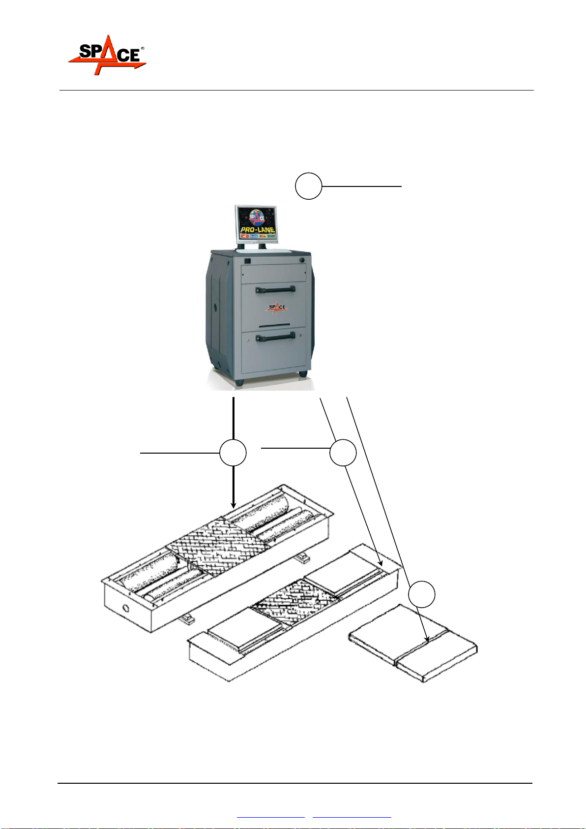
3. EQUIPMENT COMPOSITION
1
CONSOLE
(par.
3.2, 3.3 and 3.4)
2
ROLLER
BENCH
(par. 3.1)
4
Side-slip test
(optional)
par. 3.11
Adherence test
(optional)
Par. 3.10
3

User Manual
SPACE s.r.l.
Soc.a socio unico
PFB035 SERIES –PFB040 SERIES
PFB045 SERIES –PFB060 SERIES
SPRT102/4 SERIES –SPRT102/5 SERIES
SPRT102/6 SERIES –SPRT102/7 SERIES
Code M0247 - Ver.1.4
(09/2016)
Page 8/68
SPACE s.r.l. –10090 TRANA (TO) Via Sangano, 48
Tel. (+39) 011/ 934 40 300 –Fax (+39) 011/ 933 88 64
3.1. Roller assembly
The roller assemblies of the SPACE brake tester consist of a folded metal (plate) frame with
reinforcements and “C” sections for supporting and housing the operation and measurement
devices.
The roller drive system consists of a gear motor (one for each pair of rollers) constrained to a load
cell secured to the frame.
During braking, a tangential force is applied on the rollers which creates a torque resistant to the
action of the gear motor. In these conditions, the gear motor would tend to turn around the roller
rotation axis if it were not secured to the load cell.
In actual fact, the resistant torque generated by braking is unloaded on the cell.
The load cell sends a signal to the console which is used to manage result calculation and display.
Each pair of rollers features a proximity switch (called CAR-ON sensor) which indicates the
presence of a vehicle. If the support on which this is mounted is lowered, the sensor no longer
detects the support, the contact closes and an electric signal is sent to the console; this is the
signal for the motors to start.
In the event of even only one of the proximity switches not closing the contact, the console fails to
receive the signal and consequently the test is interrupted. It follows that testing is only possible
with both “rollers” lowered by the axle of the vehicle being tested.
Each pair of rollers also features a proximity switch (called TACHO sensor) that detects roller
speed and consequently vehicle wheel speed. This quantity, which is continuously measured,
when compared with the initial wheel speed, determines the slip condition that causes test stop.
Roller stoppage at the end of the test is therefore determined by the set slide threshold having
been reached. This normally coincides with detection of maximum braking force of the axle being
measured.
In the case of emergencies or special needs, the test can also be stopped by the operator, by the
remote control or keyboard.

User Manual
SPACE s.r.l.
Soc.a socio unico
PFB035 SERIES –PFB040 SERIES
PFB045 SERIES –PFB060 SERIES
SPRT102/4 SERIES –SPRT102/5 SERIES
SPRT102/6 SERIES –SPRT102/7 SERIES
Code M0247 - Ver.1.4
(09/2016)
SPACE s.r.l. –10090 TRANA (TO) Via Sangano, 48
Page 9/68
Tel. (+39) 011/ 934 40 300 –Fax (+39) 011/ 933 88 64
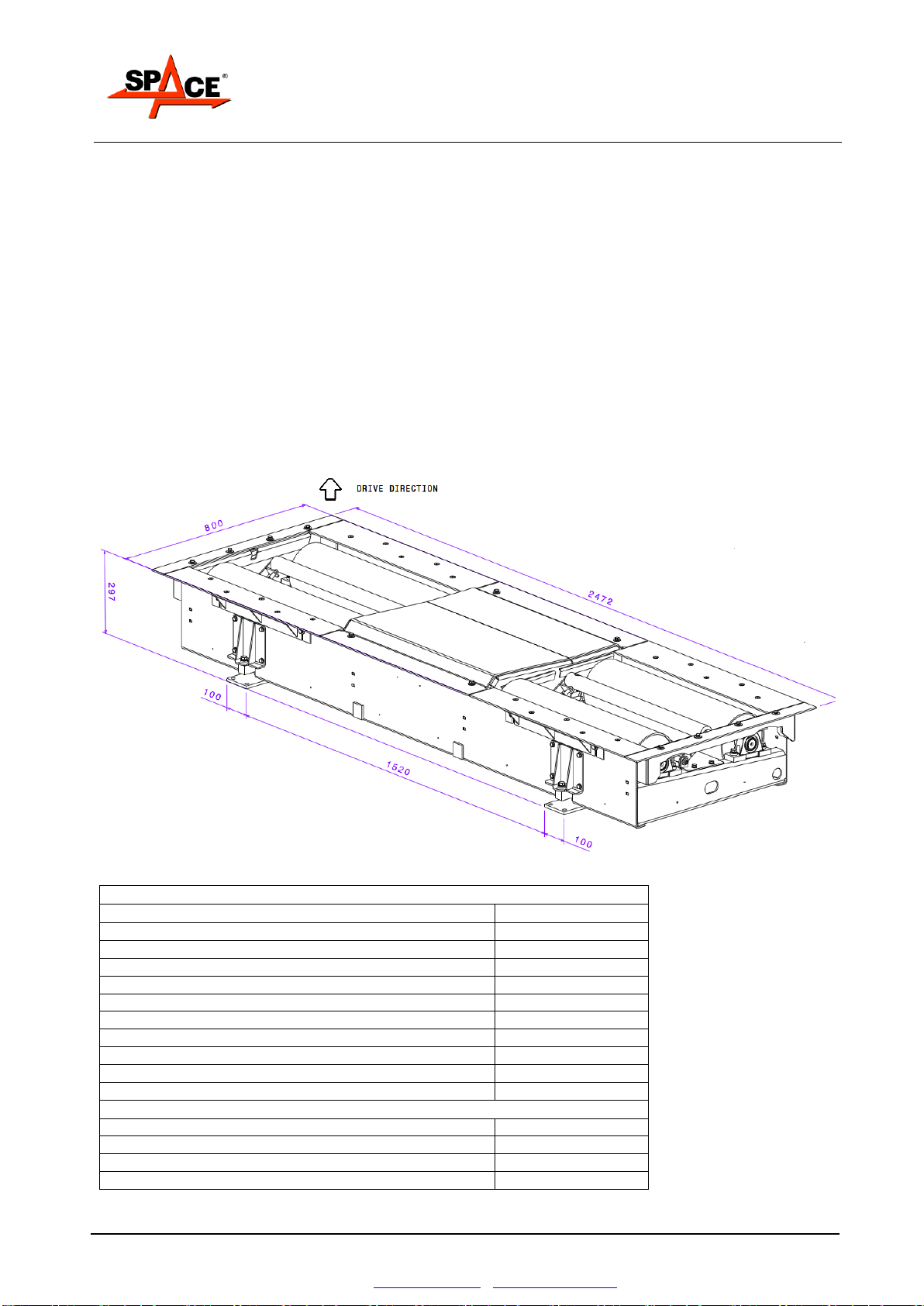
3.1.1. Roller brake tester PFB035 series
The roller brake tester PFB035 series consists of:
roller brake tester PFB035 0000 (can be used together with suspension tester code APF110);
roller brake tester with weighing equipment PFB035 2000 (2 sensor weighing equipment)
The tester is physically separate from the console; the only connections are power connections (to
power the motors) and electronic connections (signaling cables, vehicle presence, rolling speed
and measurement cables).
Figure 1
TECHNICAL SPECIFICATIONS PFB035
Roller dimensions
700 - 205
Roller internal wire distance
800 mm
Roller external wire distance
2200 mm
Max. transit weight per axle
4000 daN
Max measurable braking force
5000 N
Motors
M90 4kW
Empty roller tip speed
5,2 km/h
Grip coefficient
>0,7
Precision measuring chain
≤ ±1%
Weight
382 kg
WEIGHING FRAME TECHNICAL SPECIFICATIONS
Max. transit weight per axle
4000 daN
Max. test weight per axle
2500 daN
Precision measuring chain (2 sensor)
≤ ±3%
Weight
30kg
E.g. Roller brake tester
with weighing equipment:
PFB035 2000
E.g. Roller brake tester
without weighing equipment:
PFB035 0000
User Manual
SPACE s.r.l.
Soc.a socio unico
PFB035 SERIES –PFB040 SERIES
PFB045 SERIES –PFB060 SERIES
SPRT102/4 SERIES –SPRT102/5 SERIES
SPRT102/6 SERIES –SPRT102/7 SERIES
Code M0247 - Ver.1.4
(09/2016)
Page 10/68
SPACE s.r.l. –10090 TRANA (TO) Via Sangano, 48
Tel. (+39) 011/ 934 40 300 –Fax (+39) 011/ 933 88 64
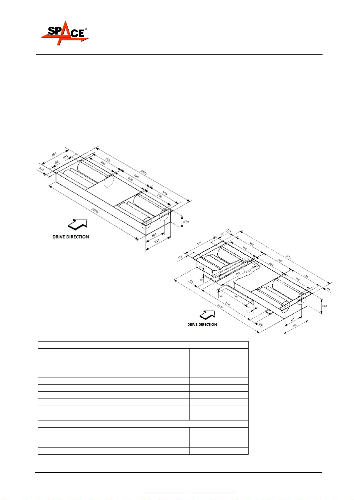
3.1.2. Roller brake testers SPRT102/4, SPRT102/5, SPRT102/6 and SPRT102/6
series with weighing equipment:
The roller brake tester SPRT102/4, SPRT102/5, SPRT102/6 and SPRT102/6 series with weighing
equipment consists of:
roller brake testers SPRT102/4P, SPRT102/5P, SPRT102/6P or SPRT102/7P with weighing
equipment;
roller brake testers SPRT102/4P4, SPRT102/5P4, SPRT102/6P4 or SPRT102/7P4 with 4
sensors weighing equipment;
roller brake testers SPRT102/4PF, SPRT102/5PF, SPRT102/6PF or SPRT102/7PF with
weighing equipment and self-braking motors;
roller brake testers SPRT102/4P4F, SPRT102/5P4F, SPRT102/6P4F or SPRT102/7P4F with
4 sensors weighing equipment and self-braking motors.
The tester is physically separate from the console; the only connections are power connections (to
power the motors) and electronic connections (signaling cables, vehicle presence, rolling speed
and measurement cables).
Figure 2
TECHNICAL SPECIFICATIONS
Roller dimensions
700 - 205
Roller internal wire distance
800 mm
Roller external wire distance
2200 mm
Max. transit weight per axle
4000 daN
Max measurable braking force RT102/4 series
4000 N
Max measurable braking force RT102/5 series
5000 N
Max measurable braking force RT102/6 series
6000 N
Max measurable braking force RT102/7 series
7500 N
Empty roller tip speed
5,4 km/h
Grip coefficient a
>0,7
Weight
385 kg
WEIGHING FRAME TECHNICAL SPECIFICATIONS
Max. transit weight per axle
4000 daN
Max. test weight per axle
2500 Kg
Precision
±2 %
Weight
30kg

User Manual
SPACE s.r.l.
Soc.a socio unico
PFB035 SERIES –PFB040 SERIES
PFB045 SERIES –PFB060 SERIES
SPRT102/4 SERIES –SPRT102/5 SERIES
SPRT102/6 SERIES –SPRT102/7 SERIES
Code M0247 - Ver.1.4
(09/2016)
SPACE s.r.l. –10090 TRANA (TO) Via Sangano, 48
Page 11/68
Tel. (+39) 011/ 934 40 300 –Fax (+39) 011/ 933 88 64
3.1.3. Roller brake testers SPRT102/4, SPRT102/5, SPRT102/6 and SPRT102/7
series without weighing equipment:
The roller brake tester SPRT102/4, SPRT102/5, SPRT102/6 and SPRT102/7 series without
weighing equipment consists of:
roller brake testers SPRT102/4, SPRT102/5, SPRT102/6 or SPRT102/7 without weighing
equipment;
roller brake testers SPRT102/4F, SPRT102/5F, SPRT102/6F or SPRT102/7F with self-
braking motors and without weighing equipment;
The tester is physically separate from the console; the only connections are power connections (to
power the motors) and electronic connections (signaling cables, vehicle presence, rolling speed
and measurement cables).
Figure 3
TECHNICAL SPECIFICATIONS
Roller dimensions
700 - 205
Roller internal wire distance
800 mm
Roller external wire distance
2200 mm
Max. transit weight per axle
4000 daN
Max measurable braking force RT102/4 series
4000 N
Max measurable braking force RT102/5 series
5000 N
Max measurable braking force RT102/6 series
6000 N
Max measurable braking force RT102/7 series
7500 N
Empty roller tip speed
5,4 km/h
Grip coefficient a
>0,7
Weight
385 kg
User Manual
SPACE s.r.l.
Soc.a socio unico
PFB035 SERIES –PFB040 SERIES
PFB045 SERIES –PFB060 SERIES
SPRT102/4 SERIES –SPRT102/5 SERIES
SPRT102/6 SERIES –SPRT102/7 SERIES
Code M0247 - Ver.1.4
(09/2016)
Page 12/68
SPACE s.r.l. –10090 TRANA (TO) Via Sangano, 48
Tel. (+39) 011/ 934 40 300 –Fax (+39) 011/ 933 88 64
3.1.4. Roller brake testers PFB040 series:
The roller brake tester PFB040 series consists of:
roller brake testers PFB040 0000 without weighing equipment;
roller brake testers PFB040 2000 with four sensors weighing equipment;
roller brake testers PFB040 1000 with self-braking motors and without weighing equipment;
roller brake testers PFB040 3000 with self-braking motors and four sensors weighing
equipment;
The tester is physically separate from the console; the only connections are power connections (to
power the motors) and electronic connections (signaling cables, vehicle presence, rolling speed
and measurement cables).
Figure 4
TECHNICAL SPECIFICATIONS PFB040 SERIES
Roller dimensions
700 - 205
Roller internal wire distance
800 mm
Roller external wire distance
2200 mm
Max. transit weight per axle
4000 daN
Max measurable braking force
6000 N
Motors
M100 4,7kW
Empty roller tip speed
5,2 km/h
Grip coefficient
>0,7
Weight PFB040 2000
415 kg
Weight PFB040 0000
385 kg
WEIGHING FRAME TECHNICAL SPECIFICATIONS
Max. transit weight per axle
4000 daN
Max. test weight per axle
2500 Kg
Precision
±2 %
Weight
30kg
E.g. Roller brake tester
with weighing equipment:
PFB040 2000
E.g. Roller brake tester
without weighing equipment:
PFB040 0000

User Manual
SPACE s.r.l.
Soc.a socio unico
PFB035 SERIES –PFB040 SERIES
PFB045 SERIES –PFB060 SERIES
SPRT102/4 SERIES –SPRT102/5 SERIES
SPRT102/6 SERIES –SPRT102/7 SERIES
Code M0247 - Ver.1.4
(09/2016)
SPACE s.r.l. –10090 TRANA (TO) Via Sangano, 48
Page 13/68
Tel. (+39) 011/ 934 40 300 –Fax (+39) 011/ 933 88 64
3.1.5. Roller Brake Testers PFB045 series
The roller brake testers PFB045 series consist of:
roller brake testers PFB045 0000 without weighing equipment;
roller brake testers PFB045 2000 with four sensors weighing equipment;
roller brake testers PFB045 1000 with self-braking motors and without weighing equipment;
roller brake testers PFB045 3000 with self-braking motors and four sensors weighing
equipment;
The tester is physically separate from the console; the only connections are power connections (to
power the motors) and electronic connections (signaling cables, vehicle presence, rolling speed
and measurement cables).
Figure 5
TECHNICAL SPECIFICATIONS PFB045
Roller dimensions
700 - 205
Roller internal wire distance
800 mm
Roller external wire distance
2200 mm
Max. transit weight per axle
4000 daN
Motors
M112 5kW
Empty roller tip speed
5,2 km/h
Grip coefficient
>0,7
Weight PFB045 0000
385kg
Weight PFB045 2000
415 kg
WEIGHING FRAME TECHNICAL SPECIFICATIONS
Max. transit weight per axle
4000 daN
Max. test weight per axle
2500 Kg
Precision
±2 %
Weight
30kg
E.g. Roller brake tester
with weighing equipment:
PFB045 2000
E.g. Roller brake tester
without weighing equipment:
PFB045 0000

User Manual
SPACE s.r.l.
Soc.a socio unico
PFB035 SERIES –PFB040 SERIES
PFB045 SERIES –PFB060 SERIES
SPRT102/4 SERIES –SPRT102/5 SERIES
SPRT102/6 SERIES –SPRT102/7 SERIES
Code M0247 - Ver.1.4
(09/2016)
Page 14/68
SPACE s.r.l. –10090 TRANA (TO) Via Sangano, 48
Tel. (+39) 011/ 934 40 300 –Fax (+39) 011/ 933 88 64
3.1.6. Roller brake testers PFB060 series:
The roller brake tester PFB060 series consists of:
roller brake tester PFB060 0000 without weighing equipment;
roller brake tester PFB060 1000 with self-braking motors and without weighing equipment;
roller brake tester PFB060 2000 with two sensors weighing equipment;
roller brake tester PFB060 3000 with self-braking motors and two sensors weighing
equipment.
TECHNICAL SPECIFICATIONS PFB060
Roller dimensions
1000 - 205
Roller internal wire distance
800 mm
Roller external wire distance
2800 mm
Max. transit weight per axle
5000 daN
Motors
M112 5,5kW
Empty roller tip speed
2,5 km/h
Grip coefficient
>0,7
Precision measuring chain (2
sensor)
≤ ±3%
Weight
485 kg
WEIGHING FRAME TECHNICAL SPECIFICATIONS
Max. transit weight per axle
5.000 daN
Max. test weight per axle
4.000 daN
Precision measuring chain
≤ ±3%
Weight
30kg
Figure 6
User Manual
SPACE s.r.l.
Soc.a socio unico
PFB035 SERIES –PFB040 SERIES
PFB045 SERIES –PFB060 SERIES
SPRT102/4 SERIES –SPRT102/5 SERIES
SPRT102/6 SERIES –SPRT102/7 SERIES
Code M0247 - Ver.1.4
(09/2016)
SPACE s.r.l. –10090 TRANA (TO) Via Sangano, 48
Page 15/68
Tel. (+39) 011/ 934 40 300 –Fax (+39) 011/ 933 88 64
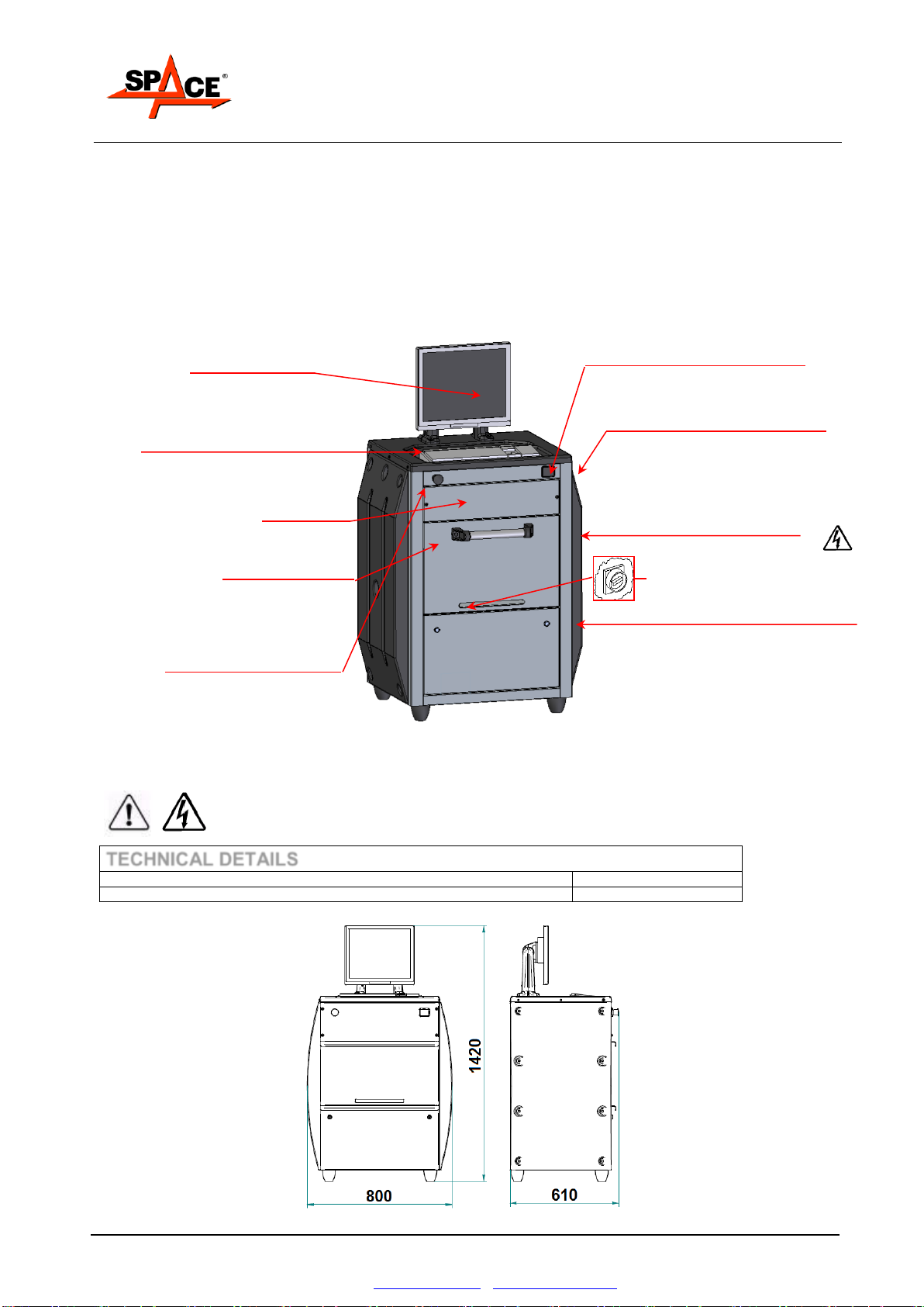
3.2. Console PFC750E000
All brake tester and suspension tester operations expect the use of a console, featuring electronic
and electric components for the processing and management of signals from the tester sensors.
Figure 7
IMPORTANT!: The rear door leading to the switchboard and the front panel leading to the CPU
board and power board can only be opened by authorized personnel; these
compartments contain high-voltage components which can prove hazardous to
unskilled operators.
TECHNICAL DETAILS
Power supply
400V 3ph + neutral
Weight
110kg
1) Monitor for displaying the choice
and sequence of test stages, initial
setting, real-time display of the test
and of the results; monitor size 19”.
Correct luminosity and contrast are
factory set.
2) 102-key PC type keyboard
4) Remote-control infrared receiver
8) Main switch/emergency device
(in the backside)
5) Printer housed behind the central door.
The test results are printed on an ink jet
printer for A4 format sheets.
.
7) On the front is a panel with a lock to key.
Inside the door is a shelf with the CPU board
for managing the signals from the different
measurement devices and the power
supply board.
6) Pictograms affixed to the machine:
Shock hazard
9) On the rear is a door with a lock to key
on which the main switch is present, (part.
8) Inside of which the switchboard is
housed for the powering of the entire
system and the starter of the motors.
3) Roller stop button. Once this has been
pressed, to reset operation, it must be
turned clockwise.
10) An IBM compatible PC can be
accessed featuring HD, an SVGA
graphic card, an RS232 serial port
User Manual
SPACE s.r.l.
Soc.a socio unico
PFB035 SERIES –PFB040 SERIES
PFB045 SERIES –PFB060 SERIES
SPRT102/4 SERIES –SPRT102/5 SERIES
SPRT102/6 SERIES –SPRT102/7 SERIES
Code M0247 - Ver.1.4
(09/2016)
Page 16/68
SPACE s.r.l. –10090 TRANA (TO) Via Sangano, 48
Tel. (+39) 011/ 934 40 300 –Fax (+39) 011/ 933 88 64
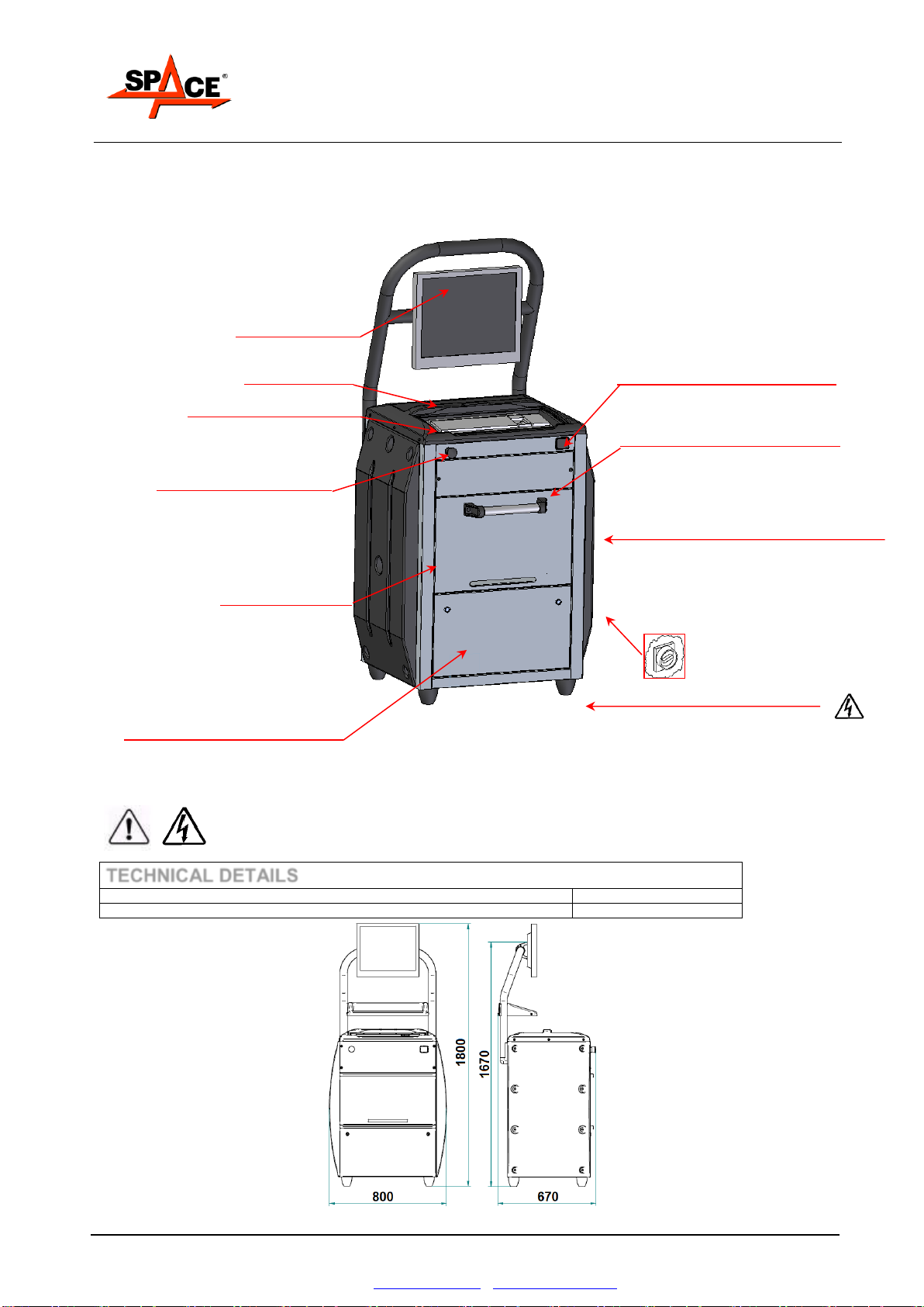
3.3. Console PFC800E000
Figure 8
IMPORTANT!: The rear door leading to the switchboard and the front panel leading to the CPU
board and power board can only be opened by authorized personnel these
compartments contain high-voltage components which can prove hazardous to
unskilled operators.
TECHNICAL DETAILS
Power supply
400V 3ph + neutral
Weight
155kg
1) Monitor for displaying the choice and
sequence of test stages, initial setting,
real-time display of the test and of the
results; monitor size 22”.
Correct luminosity and contrast are
factory set.
2) 102-key PC type keyboard
10) Remote-control infrared receiver
6) Pictograms affixed to the machine:
Shock hazard
9) On the rear is door with a lock to key on
which the main switch is present, (part. 8)
Inside of which the switchboard is housed
for the powering of the entire system and
the starter of the motors.
4) Glove compartment
7) On the front is a panel with a lock to key.
Inside the door is a shelf with the CPU board
for managing the signals from the different
measurement devices and the power
supply board.
8) Main switch / emergency device (in
the back side)
11) An IBM compatible PC can be
accessed featuring HD, an SVGA
graphic card, an RS232 serial port
3) Roller stop button. Once this has been
pressed, to reset operation, it must be
turned clockwise.
5) Printer housed behind the central door.
The test results are printed on an ink jet
printer for A4 format sheets.

User Manual
SPACE s.r.l.
Soc.a socio unico
PFB035 SERIES –PFB040 SERIES
PFB045 SERIES –PFB060 SERIES
SPRT102/4 SERIES –SPRT102/5 SERIES
SPRT102/6 SERIES –SPRT102/7 SERIES
Code M0247 - Ver.1.4
(09/2016)
SPACE s.r.l. –10090 TRANA (TO) Via Sangano, 48
Page 17/68
Tel. (+39) 011/ 934 40 300 –Fax (+39) 011/ 933 88 64
3.4. Console PFC750/WALL
Space saver control unit wall mounted.
It is available with PC, keyboard, 19 SVGA monitor and printer included or not.
Figure 9
IMPORTANT!: The door leading to the switchboard, the CPU board and power board can only be
opened by authorized personnel; these compartments contain high-voltage
components which can prove hazardous to unskilled operators.
TECHNICAL DETAILS
Power supply
400V 3ph + neutral
Precision
±0,5%
Weight
40 kg
User Manual
SPACE s.r.l.
Soc.a socio unico
PFB035 SERIES –PFB040 SERIES
PFB045 SERIES –PFB060 SERIES
SPRT102/4 SERIES –SPRT102/5 SERIES
SPRT102/6 SERIES –SPRT102/7 SERIES
Code M0247 - Ver.1.4
(09/2016)
Page 18/68
SPACE s.r.l. –10090 TRANA (TO) Via Sangano, 48
Tel. (+39) 011/ 934 40 300 –Fax (+39) 011/ 933 88 64
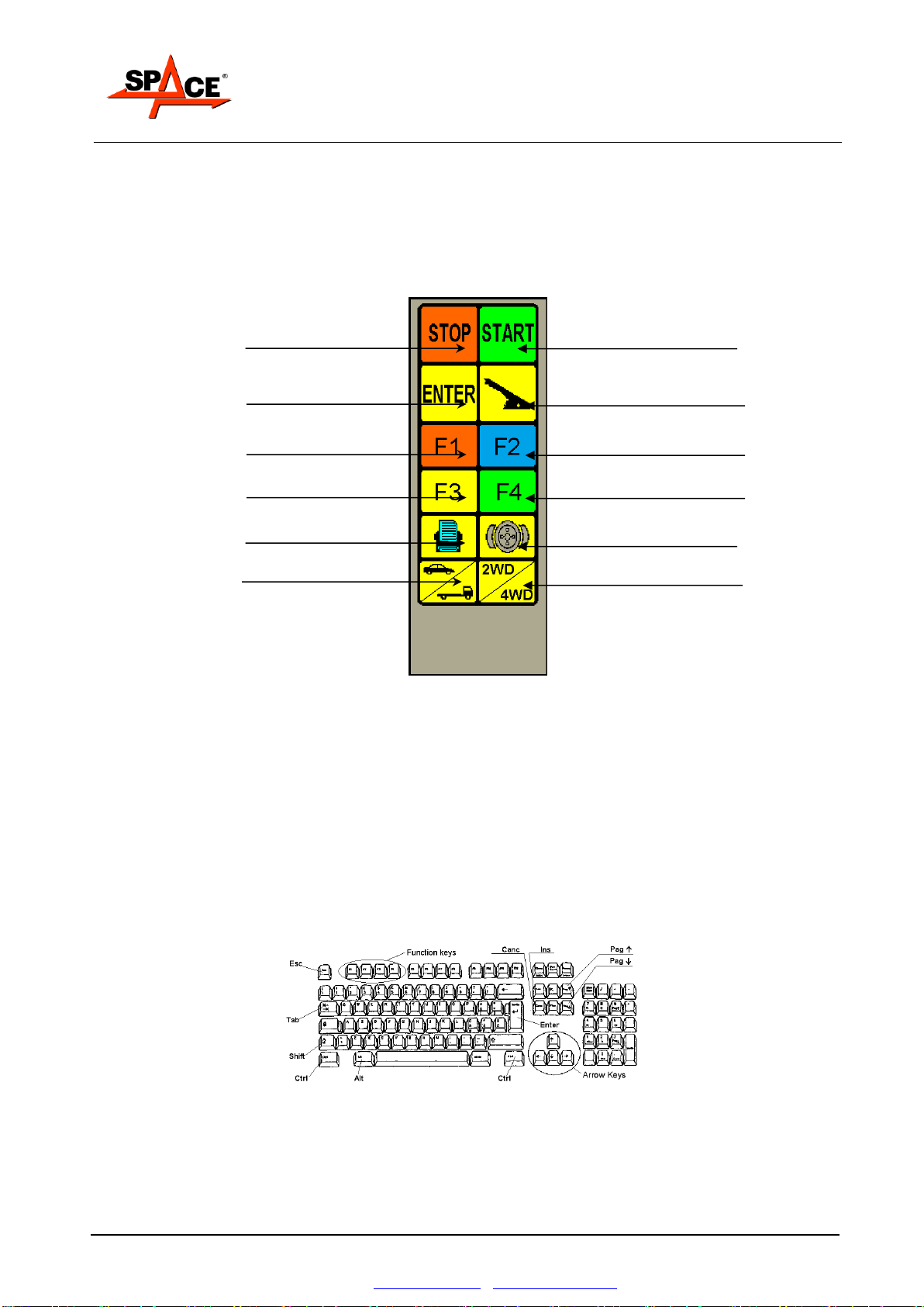
3.5. Remote control
The control interface with the console consists mainly of the 12-key infrared beam remote control.
The entire test procedure can be conducted from the remote control. Thanks to the icons, the keys
are easy to distinguish during the test.
The function keys (F1, F2, F3 and F4) take on different meanings from time to time. Reference
must be made to the graphic representation of such keys on the lower part of the monitor.
Interruption or end of test key
Test start key
Test storage key
Parking brake selection key
Function key F1
Function key F2
Function key F3
Function key F4
Print request key
Brake ovality (out-of-roundness)
procedure selection key
Car /Truck procedure selection
key
2WD / 4WD procedure selection key
Figure 10
3.6. Control keyboard
All models feature a standard 102-key keyboard connected to the PC.
The PC keyboard acts as an interface for entering details of the car, for headings, for first
configuration setting and for entering the maximum parameters acceptable for the measured
quantities.
These parameters can only be changed by qualified users according to acceptability criteria which
can change according to reference norms, specific analyses and studies, etc.
In case of faulty operation of the remote control, the test can be fully performed through the PC
keyboard on the function keys.
Figure 11
This manual suits for next models
33
Table of contents


