ACS AUTOMOTIVE DIAGNOSTIC TOOL User manual

AUTOMOTIVE
DIAGNOSTIC TOOL
Instruction Manual

02 Introduction
Introduction
The Automotive Diagnostic Tool can be used during the
installation of an alcohol interlock to determine the function
(power, ignition, start) of the wires in the vehicle main harness,
measure tach signal or locate the best position for the Digital
Tach Sensor (DTS), or simulate a tach signal to perform tests when
an alcohol interlock registers a “Tach Fault”.
WARNING!
• Do not attempt to use device to measure amperage or
AC voltage
• Do not attempt to measure voltage that may be over
+50V DC
• Failure to follow these warnings can result in damage to
the device and personal injury

Contents
Automotive Diagnostic Tool
03
Contents
Introduction......................................................................02
Contents...........................................................................03
Parts included...................................................................04
Handset function ...............................................................05
Basic function...............................................................05
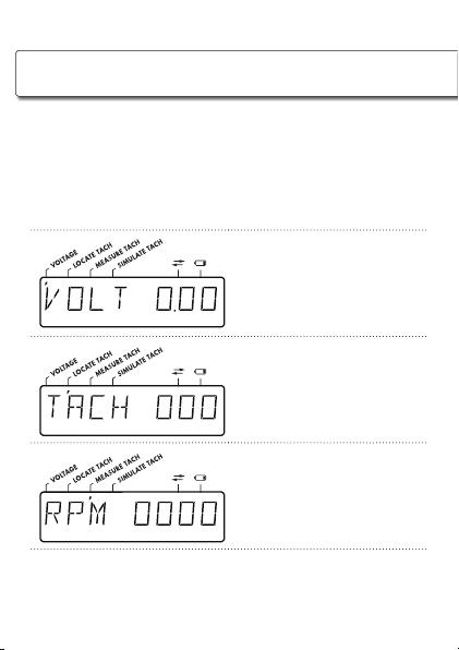
Display........................................................................06
Functions .................................................................06
Other indicators .......................................................07
Batteries ......................................................................07
Testing wire voltage...........................................................08
Determining wire function ..................................................09
Locating tach signal on alternator .......................................10
Measuring tach signal........................................................ 11
Simulating tach signal........................................................12
Troubleshooting ................................................................13
Contact information ......................................................13
Replacement parts.............................................................14
Notes ..............................................................................15

04 Parts included
Parts included
Handset
Black receptor
Display screen
FUNCTION button
ON/OFF button
USB port
Red receptor
2 x Multimeter probes
(red and black)
2 x Test leads
(red and black)
Black alligator grounding clamp Tach sensor

Handset function
Automotive Diagnostic Tool
05
Handset function
Basic function
• To turn on handset, press and hold ON/OFF (left) button for
three seconds
• When on, pressing the ON/OFF button without hold will turn
a back light on/off
• Use the FUNCTION (right) button to scroll to the desired
function
• To turn off, press and hold ON/OFF button for three seconds
NOTE:
The device has an auto-off feature that will shut it down after
it has been left idle for five minutes.

06 Handset function
Handset function
Display
Functions
Functions are shown on the display with text and comma
indicators that line up with function names on the label:
VOLTAGE
Indicated by VOLT X.XX
and comma position 1
LOCATE TACH
Indicated by TACH XXX
and comma position 2
MEASURE TACH
Indicated by RPM XXXX
and comma position 3

Handset function
Automotive Diagnostic Tool
07
SIMULATE TACH
Indicated by OUT 0900
or OUT 2250 and
comma position 4
Other indicators
Indicates RS232
communication is active
on USB connector
Indicates low battery
Batteries
The device takes two AA, 1.5V alkaline batteries.

08 Testing wire voltage
Testing wire voltage
CAUTION!
Before performing any test, it is important to ground the
Automotive Diagnostic Tool to avoid sustaining electrical
shock. To ground the diagnostic tool, insert the alligator
grounding clamp or black multimeter probe via black test lead
into black receptor on handset, then connect the clamp to
ground source or the probe to grounding wire.
1.
Turn on handset and press FUNCTION button until reaching
VOLTAGE function, indicated on display by “VOLT 0.00”
and comma position 1.
2.
Connect red multimeter probe to handset via red test lead.
Press base of probe to expose contact. Insert wire to be
tested against exposed contact and release base. This
should pinch the wire.
NOTE:
It is important to make sure the probe has sufficiently pinched
the wire in order to get a reading. If voltage is not displayed
on the device, wiggle the probe or attempt pinch again.

Determining wire function
Automotive Diagnostic Tool
09
Determining wire function
In the vehicle main wire harness, individual wire function may be
determined based on the following readings:
0
I
I
I
I
I
I
L
O
C
K
A
C
C
O
N
S
T
A
R
T
The POWER wire (continuous un-
switched source wire) will register at
approximately +12 or +24 volts in any
key position
0
I
I
I
I
I
I
L
O
C
K
A
C
C
O
N
S
T
A
R
T
The IGNITION wire (non-continuous
switched source wire) will register at
approximately +12 or +24 volts only
when the key is in the “ON” or
“START” position
0
I
I
I
I
I
I
L
O
C
K
A
C
C
O
N
S
T
A
R
T
The START wire will register at +12 or
+24 volts only when the key is in the
“START” position
Ground wire will not register any volts
under any circumstances

10 Locating tach signal on alternator
Locating tach signal on alternator
If a tach signal wire cannot be found or signal is weak, it may be
necessary to determine the best location to fasten the permanent
Digital Tach Sensor (DTS) on the alternator:
1.
Turn on handset and press FUNCTION button until reaching
the LOCATE TACH function, indicated on display by
“TACH 000” and comma position 2.
2.
Insert tach sensor into USB port on top of device.
3.
Place (DTS) sensor on the top of the alternator to determine
where the strongest signal is and move sensor around if it
is still showing a weak or no signal at all. This will be the
point that the permanent DTS needs to be fastened.

Measuring tach signal
Automotive Diagnostic Tool
11
Measuring tach signal
To determine if there is a good signal from the tach signal wire,
perform the following steps:
1.
Turn on handset and press FUNCTION button until reaching
MEASURE TACH function, indicated on display by
“RPM 000” and comma in position 3.
2.
Connect alligator clamp to black receptor and red
multimeter probe to red receptor on handset. Under the
hood, attach alligator clamp to ground source.
3.
With vehicle running, pinch tach wire with red multimeter
probe.
4.
The tach reading will be given on the display. (Make sure
to rev engine over 1000 RPM to see if tach signal is rising
and signal does not drop)

12 Simulating tach signal
Simulating tach signal
In the case that the alcohol interlock registers a “Tach Fault”, this
function is used to determine if there is a problem with the tach
signal (either in the wiring or digital tach signal) or the ECU itself.
1.
If a tach fault occurs, cut the tach signal wire and connect
red multimeter probe to wire leading to ECU.
2.
Press the FUNCTION button on the handset until
“OUT 0900” or “OUT 2250” appears on display.
3.
OUT 0900 will simulate a tach signal as if the engine
was idling. OUT 2250 will simulate a tach signal as if the
engine was revving. To switch between the two, press the
ON/OFF button while in this mode.
4.
If the ECU registers the simulated tach signal, the problem
is with the vehicle’s tach signal. If the ECU does not register
the simulated tach signal, the problem is with the ECU.

Troubleshooting
Automotive Diagnostic Tool
13
Troubleshooting
If the Automotive Diagnostic Tool is malfunctioning, send back to
ACS for maintenance or replacement.
Contact information
For assistance, contact your jurisdictional program manager.
Alcohol Countermeasure Systems Corp
60 International Boulevard
Toronto, Ontario M9W 6J2
CANADA

14 Replacement parts
Replacement parts
To order a new device or replacement parts, contact ACS and
refer to the appropriate part number(s) below:
Part name Part number
Handset 15-000408
Multimeter probe (red) 22-000827
Multimeter probe (black) 22-000826
Test lead (red) 27-000144
Test lead (black) 27-000143
Black alligator grounding clamp 13 - 0 0112 2
Tach sensor assembly with mini USB connector 13 - 0 01121

Notes
Automotive Diagnostic Tool
15
Notes

IRM-EN-60-000196-A
Copyright © 2012
ALCOHOL COUNTERMEASURE SYSTEMS, ACS and The Molly are trademarks of
Alcohol Countermeasure Systems (International) Inc. and are used under license.
Alcohol Countermeasure Systems is trading style of Alcohol Countermeasure Systems Corp.
acs-corp.com
Table of contents