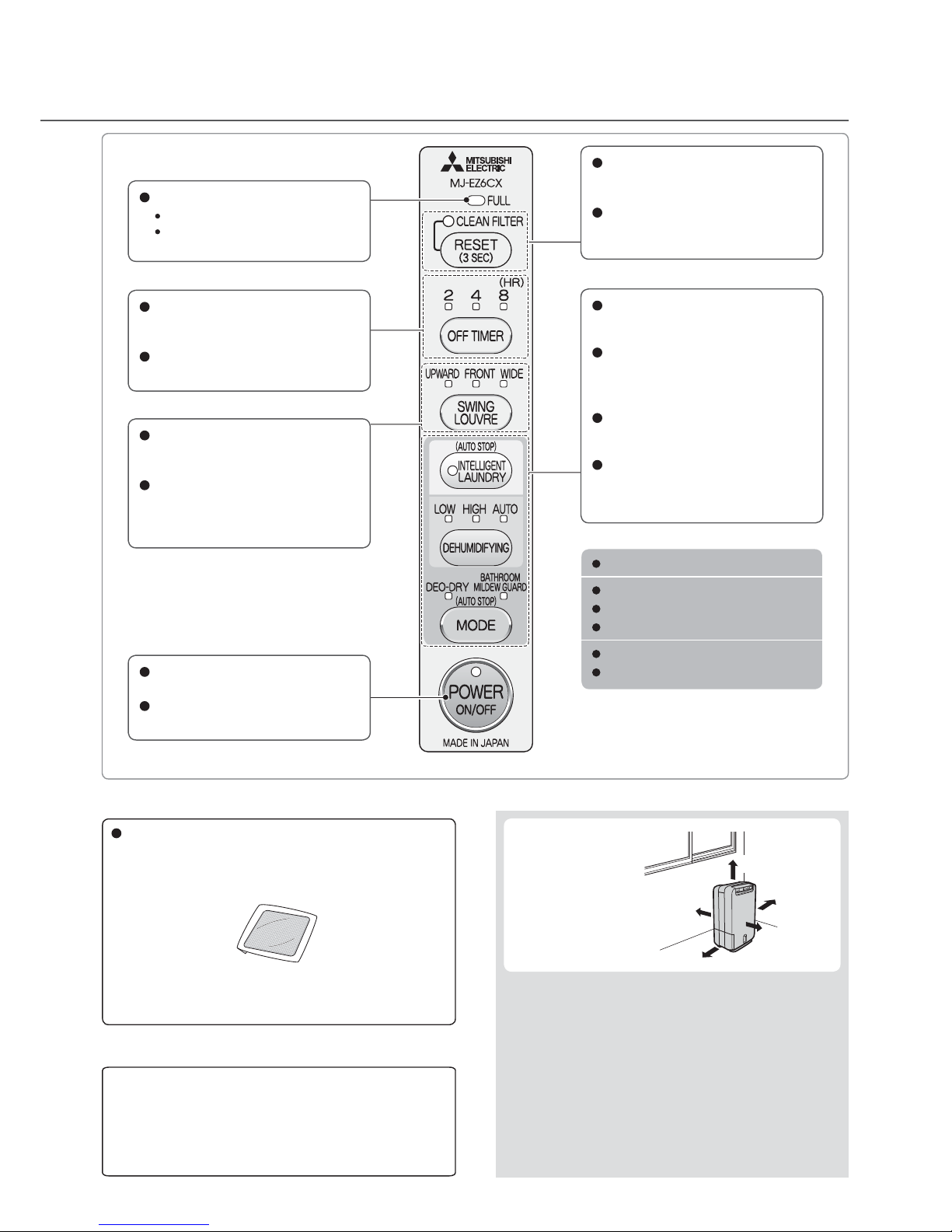
Mitsubishi MJ-EZ6CX-S1-IT User manual

2010
DEHUMIDIFIER
SERVICE MANUAL
Model MJ-EZ6CX-S1-IT
MITSUBISHI ELECTRIC
ADVANCED AND EVER ADVANCING
No.MJW-10020
Sold from 2010
CONTENTS
1. Precautions ...............................................................................................................2
2. Names and Functions of Parts (Front, Back, Control panel, Accessories) .........4
3. Specifications ...........................................................................................................6
4. Outer Dimensions ....................................................................................................6
5. Wiring Diagram .........................................................................................................7
6. Function ....................................................................................................................8
7. Technical Points ......................................................................................................11
8. Time Charts .............................................................................................................12
9. Circuit Diagram .......................................................................................................14
10. Precautions for failure diagnosis ..........................................................................16
11. Troubleshooting Procedure ...................................................................................17
12. Troubleshooting ......................................................................................................28
13. Maintenance ............................................................................................................30
14. Service Checklist ....................................................................................................32
15. Precautions for Disassembly and Reassembly ...................................................33
16. Disassembly and Reassembly Hints .....................................................................35
17. Parts Catalog ...........................................................................................................44

Meanings of the graphic symbols used in this manual and on
the unit are explained below.
PrecautionsPrecautions
Forbidden
Keep away
from fire
Do not
subject to
water
Do not
disassemble
Always
follow the
instructions
The following diagrams indicate circumstances
where danger can result from mishandling the unit.
WARNING
Mishandling may result in
fatal or serious injuries.
Mishandling may result in
injuries or damage to your
home or property, etc.
Do not damage or modify the power
cord or plug. Do not use power sockets
in which the plug fits loosely.
Do not modify, bundle, twist, bend or heat the power
cord. Do not place under objects or use with the end
close to the plug bent.
(Keep pets from biting the cord.)
The cord may be damaged resulting in fire,
electric shock or heat generation.
Do not plug many power cords
into one power socket.
This may result in fire, electric shock or
malfunctions.
Do not start/stop the unit by
plugging/unplugging the power cord.
This may result in fire and/or electric shock.
To prevent the temperature inside the unit from
rising, the blower fan rotates for approximately
2 minutes after the power button is turned off.
Remove the power plug after the blower fan
has stopped.
Do not put the unit near heat-
generating devices (such as
stoves, fan heaters,
etc.).
The plastic parts may melt and cause fire.
Do not put your fingers
or any long object, into
the air intake/outlet.
Do not touch the swing
louvre.
The internal fan rotates at high speeds,
and such actions may
result in injury or
malfunctions.
Do not attempt to repair,
disassemble, or modify
the unit.
This may result in fire and/or electric shock.
Refer servicing to your dealer or Mitsubishi
Electric Service Centre.
Exclusively use 230V AC power
sockets for the power supply.
Failing to do so may result in fire and/or
electric shock.
*Use an extension cord by itself.
Wipe dust off the power plug and
insert the plug firmly.
If the plug is not fully inserted into the socket,
dust may gather on the connectors which may
cause fire and/or electric shock.
Should abnormal symptoms occur (a
burning smell, etc.), switch off the unit
and unplug it from the socket.
Continuing to operate the unit may result in
fire, electric shock, or malfunctions.
Contact your dealer or Mitsubishi Electric
Service Centre for consultation.
Remove water that has collected in
the tank.
Accidentally drinking the water or using it for
other purposes may cause illness and/or
unforeseen accidents.
WARNING
1. Precautions
CAUTION
2

CAUTION
Do not stand on, sit on or lean against
the unit.
The unit may tip over causing injury.
Do not drain water continuously if
there is a possibility that temperature
around the hose could drop to
freezing point.
Water inside the hose may freeze and prevent
the water in the tank from flowing out. The
water may leak from the unit and damage
surrounding objects.
Install the unit in a location where the
floor is flat and stable.
If the unit falls over, the water collected in the
water tank may leak damaging surrounding
objects and in turn result in fire or electric
shock caused by an electric leak.
Before moving the unit always switch
it off, unplug it and remove water
from the water tank.
Moving the unit with water in its tank may
cause the water to leak and damage the
surrounding objects and in turn result in
electric shock and/or an electric leak.
Do not point airflow from the unit directly at
the body for a prolonged period of time.
Be especially careful when using
the unit where there is
someone who is unable to
adjust the humidity (infant,
child, or elderly person).
If air-flow is directed at
the body for long periods, it may harm one’s
physical condition and lead to dehydration.
Do not remove the Styrofoam
from the floating element.
The floating element will not
be able to detect a full tank
resulting in water leakage, which
may damage surrounding objects or cause
electric shock and/or an electric leak.
Grasp the plug and remove
from the power socket.
When removing the plug from the
power socket, do not pull on it
diagonally or by the cord as this may cause the
projections/wiring to be damaged resulting in
a short circuit, electric shock or fire.
Before cleaning the unit, wait
until the blower fan stops
after operation has stopped,
and then remove the power plug.
When the unit is on, the internal fan rotates at high
speeds and may cause injury.
Do not cover an air outlet or
air intake with laundry, cloth,
curtain, etc.
This results in poor ventilation and
may cause heat generation/fire.
Do not put vases or any other objects
filled with water on the unit.
Water may leak into the unit adversely
affecting electric insulation and cause
electric shock and/or fire by short-circuiting.
Do not use the unit in a
bathroom or other
location where it is likely
to come into contact with
water, or wash it with water.
Exposure to water may result in fire or
electric shock caused by an electric leak.
Do not use the unit where it
may be exposed to direct
sunlight or other weather
conditions.
(This unit is for indoor use only.)
This may cause overheating, electric shock
and/or fire caused by an electric leak.
Do not use the unit in narrow,
enclosed places such as
inside closets, between
pieces of furniture, etc.
This results in poor ventilation and may cause
heat generation and/or fire.
Do not use combustion
appliances in the path
of the air outlet.
This may cause incomplete
combustion in the appliance.
Do not use the unit in places that may be
subject to oil or flammable gas leakage.
Such a leak around the unit may cause
combustion and fire.
Do not use the unit in places where
chemicals are used (such as hospitals,
factories, laboratories or beauty salons).
Chemicals and solvents evaporated in the
air may harm the unit and cause water in
the tank to leak, resulting in damaged to
property.
Do not use the unit for
special purposes, such
as preservation of food,
art or scientific works.
This may negatively affect the quality of the
items stored.
Note) This page is extracted from the instruction manual.
3

Unplug the unit from the power
source when not using the unit
for an extended period of time.
Otherwise it may cause fire and/or
electric shock caused by an electric
leak.
When using the continuous
drainage outlet, make sure to
position the hose so that the
water drains without obstruction.
The water in the tank may leak and
damage surrounding objects.
When draining water
continuously or left unattended
for long periods, inspect the unit
every two weeks.
Do not allow debris to clog the filter/
hose as this may cause overheating/
leakage.
First remove the water
from the tank and then
grasp the handle firmly
when moving the unit.
The falling or dropping of the
dehumidifier may cause an
injury, damage to the floor,
or household belongings
becoming wet as a result of
water spilling out of the tank.
Use the unit with caution in
rooms where the walls, furniture
and art work are vulnerable to
dry air, as it may cause cracks
and warping.
Keep the unit always in an upright position.
Inclining the unit may cause water in the tank to leak
into the unit, resulting in malfunction. Should you
incline the unit accidentally, contact the place of
purchase for advice.
Do not carry the unit horizontally.
This may result in malfunctions.
Warnings
Names and Functi
Front
Back
CAUTION
Continuous
drainage
outlet
Power plug
Air intake
There is a filter inside the unit.
It cannot be removed.
Filter cover
Do not cover.
Water level
window
Handle
Raise the handle to
carry the unit.
Sensor (inside unit)
Do not cover.
Silver ion
sterilizing and
deodorizing filter
The water tank may contain water residue at time of
purchase. This is from final product testing at the factory
and is not due to a defect.
Downward blowing
louvre
Tank lid
Water tank
Control panel
Floating element
Louvre (air outlet)
2. Names and Functions of Parts
4

ons of Parts
Silver ion sterilizing and deodorizing
filter
Hereafter referred to as simply “sliver ion filter.”
The silver ion filter is supplied with the unit at the time
of purchase. Set before using the unit.
Accessories
What is a silver ion sterilizing and deodorizing filter?
At least 50 cm
At least
2 cm
At least
40 cm
Installing your
dehumidifier
Make sure to leave
some space around
the unit.
<When installing your dehumidifier near a wall>
Stop the swing operation and use the louvre in the
upward direction. Since the wind blown out of the
unit mixes with the dust in the air, dust may stick to
the wall and make it dirty if the wind is blown directly
onto the wall.
<Operating noise>
Use the unit on a mat or the like. This reduces
vibration and noise. It also prevents leaving
depressions on carpets, etc.
At least
20 cm
At least 50 cm
The silver ion sterilizing and deodorizing filter is a filter
consisting of fibres containing special deodorant and
silver ion anti-bacterial agent (anti-allergen, anti-virus,
and sterilization).
Cigarette smoke and toxins found in smoke, such as
carbon monoxide, cannot be removed with this filter.
POWER lamp
Lights during operation.
POWER switch
Turns the power on/off.
CLEAN FILTER lamp
Flashes or lights to notify you that it
is time to clean the filter.
RESET switch
Cancels the flashing or lit state of
the CLEAN FILTER lamp.
Control panel
FULL lamp
Lights when the tank is full.
Lights when the tank is not
attached to the unit.
OFF TIMER lamps
Indicates the OFF timer remaining
operation time.
OFF TIMER switch
Sets the OFF timer operation time.
SWING LOUVRE lamps
The lamp for the swing direction of
the louvre lights.
SWING LOUVRE switch
Changes the swing direction of
the louvre, or stops the swing
operation.
Operating mode lamps
The lamp of the selected operating
mode lights.
INTELLIGENT LAUNDRY
switch
Switches to the Intelligent laundry
operation.
DEHUMIDIFYING switch
Switches to the dehumidifying
operation.
MODE switch
Switches between the clothes
deodorant operation and bathroom
mildew guard operation.
INTELLIGENT LAUNDRY
LOW
HIGH
AUTO
DEO-DRY
BATHROOM MILDEW GUARD
You can select one of the six operating
modes above.
It is not possible to use a combination
of two operating modes.
At least 50 cm
At least
2 cm
At least
40 cm
Note) This page is extracted from the instruction manual.
5

3. Specifications
324
485
115
190
50
4. Outer Dimensions
The dehumidifying capacity is a value obtained when the dehumidifier is continuously run at a room temperature
of 30°C and relative humidity of 80%. It indicates the amount of dehumidification per day (24 hours).
Standby power approximately 1W.
-S1-ITXC6ZE-JMledoM
zH05V032esahpelgniSylppusrewoP
yad/L0.6yticapacgniyfidimuheD
Power
consumption
590WHGIH
305WWOL
Operating
sound
Bd73/64WOL/HGIH
dB94yrdnuaL
Water tank capacity stops automatically at approx. 2.4L
gk0.7thgieW
Dimensions (H × W × D) 485mm × 190mm × 324mm
Note) This page is extracted from the instruction manual.
6

P9
SM
P21
P8P14
P1 P3
P11
S
P12
P20 P31
P13
S
Power control board
P2P5
P4 P7 P10
P6
Power plug
Green
Red
Red
Red
Blue
Brown
Blue
Blue
Ye l l o w
Yellow
Black
Black
Black
Black
Gray
Gray
Black
Black
Black
White
White
White
White
White
White
White
White
White White
Black
White
Orange
Frame
thermal fuse Heater
Rotor
motor
Heater thermal
fuse
Dryer
fan
motor
Blower
fan
motor Photo
Interrupter
Frame
thermistor
Float
switch
Heater
thermistor
Room temperature
humidity sensor
Stepping
motor
Operation control board
1)Wiring Diagram
2)Board Diagram
[Operation control board ]
[Power control board ]
5. Wiring Diagram
7

OFFOFFOFF
OFF
OFF OFF OFF OFF
OFF OFF OFF OFF
OFF OFF OFF OFF
ONHi
Hi
Hi
Hi
Hi
Hi
Hi
Hi/Lo
/OFF Hi/Lo
/OFF
HiON
ON
Lo LoON
○
○
○
○
○○
○
○
○
○
○
○
○
−
−
−
−
−
−
−
−
−
−
−
−
−−
−
−
−
○
○
○
○
○
○
○
○
○
○
○
○
○
○
○
○
○
○
○
○
○
○
○
○
○
○
○
○○○○ ○
○
○
○
○
○
○
○
○
○
○
○○○○○ ○
○
○
ON ON
ON ON
ON ON
ONLo ON OFF
ON/
OFF ON/
OFF
Lamp indications
Primary operation
Secondary operation
Switch
×××
○×
×
××
○
○
○
×
○
×
○
×
○×××
×
×
×
×
×
×
○
×
×
×
○
○
○
○
○
○
○
○
×
○
×
×
×
×
○
×
○
×
○○×
×
×
×○××
○× ×
×
×
○
×
×
×
×
○
○
○× ×
*1Operation after after-blow stops (fan stops).
*2Upward, front, wide
*2
*1
*1
○
○
○○
ڦFunction List
ڦTransition of state during stop mode
Blower fan
Dryer fan
Rotor
Heater
Power
Low
High
Auto
Intelligent laundry
Deo-dry
Bathroom mildew guard
Swing louvre
Off timer
Full
Clean filter
Power
Mode
Dehumidifying
Swing louvre
Off timer
Reset
Intelligent laundry
ڦDehumidifying
ࠈ㸝1㸞High࣬Low
6. Function
Operation Off
Low
High
Auto
Intelligent laundry
Deo-dry
Bathroom mildew guard
After-blow
Tank full
Clean filter lamp / lighting
Timer OFF
Operation Off
Timer Off
Intelligent laundry Off
Dehumidifying Off
Deo-dry Off
Tank full
Clean filter
Room temperature anomaly
HT,HEX
Temperature anomaly
Temperature conditions
Humidity conditions
Blower fan
Heater
Dryer fan
Blower fan
Heater
Dryer fan
Heavy load conditions
35Υor more
Humidity less than 40 %
Rank 4
Lo
ON
Rank 2
Lo
ON
Normal load conditions
35Υor less
Humidity 40% or more
Rank 3
Hi
ON
Rank 1
Lo
ON
ې㸯Lighting / operable
㸢㸯Lighting depending on the conditions
ې㸯Operation
㸯Release, No operation
*1Only when circulating
*2After-blow continues
*3Operable before it stops
Operation Off
Timer Off
Intelligent laundry Off
Dehumidifying Off
Deo-dry Off
Tank full
Clean filter
Room temperature anomaly
HT,HEX
Temperature anomaly
*1
*3
*3
*2
●When either temperature conditions or humidity conditions become heavy load conditions,
operation changes to the following content.
Low High
*1
Temperature conditions on this
table indicate the value at
which
the operation always
changes
to the normal load
operation. Temperature
conditions here
are different
from the software
*1
8

Humidity
70%
ON
OFF
Operation starts Operation stops
Operation A
1-12 hours Auto stop
Operation B
Operation A
↓
60%
50%
27℃20℃
Humidity
Set humidity 60%
Set humidity 50%
When humidity exceeds 60%,
lower it by less than 50%
Blower fan,
&T[GT fan,
rotor, and
heater stop
Circulating operation
Blower fan only
Temperature
Blower fan,
&T[GT fan,
rotor, and
heater stop
Dehumidifying
Blower fan
40㨪120
sec.
30 minutes
Operation
OFF
After-blow
After-blow
Heater
Dryer fan
Rank4 (Hi)
ON
OFF
Hi
OFF
OFF
Rank3 (Mi)
Rank1 (Lo)
①Control Summary
■Intelligent Laundry
①Control Summary
(a)The dehumidifying time changes depending on the humidity, temperature and time.
(b)The time when the humidity changes is measured, and dehumidifying operation is automatically stopped
when the laundry is dry (1-12 hours).
■Deo-dry
①Control Summary
(a)Odors are removed by heating the clothes.
60 minutes
2 minutes2 minutes
Deo-dry
sw
(a)The operation is shifted among 60%
setting,50% setting,and circulating
operation, depending on the room
temperature.
㧔2㧕Auto
9
Temperature Conditions 35℃or less 35℃or more
70%-
(Operation A)
Blower fan Rank 6 Rank 4
Heater Hi Lo
Dryer fan ON ON
30%-69%
(Operation B)
Blower fan Rank 3 Rank 4
Heater Hi Lo
Dryer fan ON ON

Minimum operating time (4 or 6 hours)
Elapsed time (hour)
Change of URRP humidity (%)
50% For 4 or 6 hours.
Auto stop
Louvre:
wide
→
front
Louvre: front
4ࠈ〜 6
3.532.521.510.50
20
30
40
50
60
70
100
90
80
Basic operation
Humidity
Start
Wide
After achieving 50%
Front
Fan control
Louvre
High
■Fan Rank
■Bathroom Mildew Guard
①Control Summary
(a)Preventing the growth of mildew by lowering the humidity in the bathroom.
(b)The dehumidifying time changes depending on temperature and humidity, and it stops automatically
(Minimum 4 hours, Maximum 12 hours).
(c)The direction of louvre automatically changes depending on the humidity, temperature and time.
Target part
Operation
Heater
ON
Blower fan
Hi
Dryer fan
Hi
Louvre
Wide→Front
Minimum operating time
20Υor more 4 hours
Less than 20Υ6 hours
Lo (B)
Lo (A)
Hi
HH
Dehumidifying
Intelligent laundry
Air amount (/min)
1.09
1.20
1.78
1.78
1.78
1.93
−
Rotation speed (rp m)
790
860
1250
1250
1250
1350
2700
Rank 1
Rank 2
Rank 3
Rank 4
Rank 5
Rank 6
Rank A〜D
Blower fan
Dryer fan
10

Room temperature may rise 3-6°C during operation.
The dehumidifier does not have a cooler function. Due to heat produced during operation, the room temperature may rise
3-6°C. As a result, the unit may blow warm air, but this is not due to a malfunction. (During winter, the air may not feel warm
as the temperature is below body temperature.)
The unit can operate in a room temperature range of 1-35°C.
However, if the room temperature exceeds 35°C, the unit may operate in blower mode or increase the airflow. This is
because the temperature within the unit rises causing the protection mechanism to operate. In order to lower the internal
temperature of the unit, use the unit with the swing stopped and louvre vertical.
If the temperature is over 40°C, the unit will operate in blower mode without dehumidifying.
If the temperature is below 1°C, the extracted water is close to freezing disabling the dehumidification, and only the
blower is operating.
The amount of dehumidifying becomes less when the humidity
becomes approximately 40% or less or the room temperature becomes
approximately 35°C or more.
If the humidity becomes approximately 40% or less or the room temperature becomes approximately 35°C or more, the
amount of dehumidifying becomes less because operation is performed with the power consumption of the heater reduced
to a level equivalent to that of LOW mode.
The blown air may cause smell during operation.
An odor may be emitted from the parts inside the dehumidifier when you first use the dehumidifier.
Odorants that cannot be removed by the silver ion filter may be absorbed by the dehumidifier rotor inside the unit.
Odors unique to zeolite (sour smell, burning smell, etc.) may be emitted from the dehumidifier rotor. These odors have
no effect on humans and animals.
If the room contains any of the following items, the corresponding odor will be absorbed by the dehumidifier rotor inside
the dehumidifier. Also, that absorbed odor will be heated by the heater, which may result in a burning like smell or other
abnormal odor.
Examples: Cigarettes, cosmetics, hair dressing products, building materials, new furniture, etc.
Absorption of moisture
Discharge of moisture
How does dehumidification work?
①Air is drawn from the room, moisture is absorbed
by the dehumidifier rotor, and dry air is blown
out.
②The dehumidifier rotor is heated with a heater,
and the absorbed moisture is discharged inside
the heat exchanger.
③The discharged moisture is cooled by the heat
exchanger, causing it to transform into droplets,
which is collected in the water tank. Dehumidifier
rotor
Moist air
Dry air
Heat exchanger
Heater
Water tank
Features of this dehumidifier
7. Technical Points Note) This page is extracted from the instruction manual.
11

8. Time Charts
Operation OFF
Intelligent laundry
Tank full lamp lighting
120 Sec. 120 Sec.
Tank full
3
S
ec.
Intelligent laundry
Operation
OFF
Float
OFF
Float
ON
Switching the operation mode
ON
OFF
ON
OFF
ON
OFF
Low lamp lighting
High lamp lighting
Deo-dry lamp lighting
Bathroom mildew guard lamp lighting
ON
OFF
2 Sec.
2 Sec.
2 Sec.
2 Sec.
ON
OFF
Open
Close
ON
OFF
40㨪120 Sec.
Continuous lowLow Continuous highHigh Deo-dry
State / Operation
Mode
Indications
Tank full lamp
Blower fan
Dryer fan
Rotor
Louvre
Heater
(for high and low)
Heater
(for high)
Operation
ON Mode
ON Mode
ON
Dehumidifying
ON
Bathroom mildew guard
ON
Intelligent laundry
Intelligent laundry
lamp lighting
40㨪120
Sec.
12

After-blow
120
seconds
ON
OFF
ON
OFF
ON
OFF
OFF
ON
Open
Close
Clean filter lamp
flashing
Operation
OFF
Total operating hour
of blower fan 150 Hr elapsed Total operating hour
of blower fan 300 Hr elapsed
Operation
ON
Operation
OFF
Operation
ON
Operation
ON
Clean filter lamp
flashing
Clean filter lamp
lighting
Clean filter lamp
lighting
High High
40㨪120
Seconds
40㨪120
Seconds
Normal
display
High
2Hr lamp
lighting
OFF
timer
ON
8Hr lamp lighting
4 Hr elapsed
4Hr lamp
lighting 2Hr lamp
lighting
2Hr elapsed 2Hr elapsed
OFF
timer
ON
OFF
timer
ON
State / Operation
Mode
Indications
Blower / Dryer
fan
Rotor
Louvre
Heater
(for high and low)
Clean filter OFF timer operation
Filter
reset
No lamps are
lighting
After-blow
120 seconds
Alarm Alarm Alarm Alarm
4Hr lamp
lighting
40㨪120
Seconds
Deo-dry
OFF
ON
ON
OFF
OFF
ON
Open
Close
Deo-dry lamp lighting
Mode
ON
30 minutes elapsed 30 minutes elapsed
After-blow
120 seconds
Fan rank 4
Bathroom
mildew guard
Fanrank3
Fan rank 3 Fan rank 4
Operation
ON
No lamps are
lighting
Bathroom mildew
guard lamp lighting
Deo-drylamp
lighting
State / Operation
Mode
Indications
Blower fan
Rotor
Louvre
Heater
Deo-dry
Deo-dry
Deo-dry
13

FH1
AC250V
6.3A
P1
VH-2(3)
TEMPFUSE
(HEATER)
172℃
HEATER 4
34
7
1
34
34
ZNR1
Z10D471
G5CA-E
RY4
RY1G5CA-E
RY2G5CA-E
XA-2(4)
P5
R1
1W100
C3
250V333
86
PC1
AQH3223
P4
VH-3(7)
5V 5V
+ +
SSR1
AQG12212
1
3
21
5
BLOWER
FAN
MOTOR
P6
VH-3(5)
VH-2(3)
P7
23
RY3
G5NB
C4
400V1.5u
R12
1/2W820k R5
1/2W68k R35
4.7k
ZD2
4.7B C26
103
D4
1A600V R2
2W200
C11
400V4.7u C12
400V4.7u
D5
1A600V
L3
C10-FR
R3
1/2W10
R8
1/2W2M
C2
250V104
1/2W220k
R6 1/2W220k
R4
R23
30k ZD1
4.7B C21
103
R21
4.7k 10k
R22
C22
473
C35
103
D
FP BP
S
S
SS
+
+
+
C25
473
R24
2k2% R25
13k2% 50V10u
C13
16V47u
C10
D7
1A600V
L2
C13-FR
D6
EG1A C14
R39
10k
+12V
1
2
1SS133
D12
RY1
G5CA-E
TR3
2SC5395
5V
5V
PHOTO
INTERRUPTER
PH- 3
P14
3
2
1
R68
4.7k
R69
24k
300
R70
+12V
1
2
1SS133
D13
RY2
G5CA-E
TR4
2SC5395
1SS133
D20
RY4G5CA-E
DTR6
RN2206
DTR5
RT1N234S
1SS133
D14
RY3G5NB
14
R7
1/2W750
PC1
AQH3223
SSR1
AQG12212
23
34
+12V
D15
C5
NONINSERT
(BLK)
225W
325W
Hi
Hi&Low
TR1
2SC5395
25V
1000u
TR2
2SC5395
1
2
78
5
34
IC4
LNK306
21
3
1
AC230V
P2
VH-2(4)
4
1
172℃
P3
VH-2(4)
4
1
TEMPFUSE
(FLAME)
121℃
121℃
R13
2M
C1
250V224
(BRW)
(BLU)
(BLU)
(RED)
(GRN)
(RED)
(WHT)
(YLW)
1
4
(WHT)
DRYER
FAN
MOTOR
(BLK)
(YLW)
(BLU)
3
1
(BLK)
ROTOR
MOTOR
P8
XA-5
1
2
3
4
5
+12V
LOUVRE
(WHT)
R42
10k
D16 D17 D18
1SS133×4
N
L
T6.3AH250V
L1
JUMPER
R34
22k
+12V
9. Circuit Diagram
14

R52
5.1k
23
4
INT2
TEST
+12V
IN
C
GND
5V
OUT
RST
+
5V
100
R26
C36
103
C23
103
RESET
D19
1SS133
IC2
R20
22k
C19
16V47u
5V
33
100
R71
R73
100k
R72
200
C38
103
AHF22
13
24
TSW
5V 5V
R36
4.7k 10k
R37
C39
103
C27
103
20 P15
P37
P17
P16
P34
P21
P22
P14
P20
P47
P46
P45
P44
R40
1k
+
50V3.3u
C15
1SS133
D8
D9
1SS133
+
C17
50V10u
4.7k
R38
+
1SS133
D10
D11
1SS133
+
5V
IC3 M54566FP
9
16
15
14
13
12
11
10
8
7
6
5
4
1
2
3
C28
473
CST1
(4MHz)
32
XOUTXIN
5V
Vdd Vref AVdd VAss Vss
P04
P05
P06
P07
C29
473
C30
103
53534 36 1
P01
P40
P41
P42
P43
P10
P11
P03
P02
P36
DVO
P32
P33
P30
P00
P31
5V
330
R44
330
R45
330
R46
330
R47
4.7k
R48
4.7k
R49
10
9
8
7
6
5
4
3
2
1
1
2
3
4
5
6
7
8
9
10
PH-10
P21 PH-10
P31
R51
4.7k R50
4.7k
5V
R63
10k
C33
103
R62
68k
R67
11k2%
R66
11k2%
R64
39k2%
R65
4.7k
C34
102
EH-4
P9
4
3
2
1
TEMP&
HUMI
SENSOR
C40
103
C31
103
C32
103
4.7k
R60
4.7k
R61
R28
1k
R59
1k
11
27
10
26
29
28
5V
5V
R53
33k2%
R54
33k2%
5V
5V
3.9k
R55
PH-6
P10 PH-6
P20
FLOAT
P12
XA-2
P13
XH-2
P11
EH-2
THERMISTOR
HEATER
THERMISTOR
FRAME
5V
C37
103
BZ1
2.4k
R27
1
2
4
5
61
4
3
2
3
5
6
EEPROM
5V
R18
22k R17
22k
R19
820
5V
Vcc Vss
WP
A0
A2
SDA
SCL
6
5
84
7
3
2
1
IC5
OFFTIMER
KEY1 SWING
KEY2 DEHUMI
KEY3
MODE
KEY4 POWER
KEY5
1SS133
D23 1SS133
D21 1SS133
D22
DTR1
RN2206
DTR2
RN2206
DTR3
RN2206
DTR4
RN2206
14
15
16
17
37
38
39
40
25
24
13
12
32
22
UPWARD
LED1
(G)
WIDE
LED2 LOW
LED3
BATHROOM
LED6
RESET
1SS133
D24
MODE
KEY6 TIMEUP
NONINSERT
C20
473
C24
473
8
5
4
3
2
1
L78LR05C
18
19
30
6
7
21
41
42
43
44
9
R43
1k
50V3.3u
C16
C18
50V10u
4.7k
R41
5V
R31
10k
(MODELCHANGE )
R33
NONINSERT
A1
31 P35
5V
TMP86CH47AUG IC1
MILDEWGUARD
(G) (G)
AUTO
LED4
(G)
DEO-DRY
LED5
(G) (G)
CLEANFILT
LED7
(R)
FULL
LED8
(R)
2Hr
LED9
(Y)
4Hr
LED10
(Y)
8Hr
LED11
(Y)
POWER
LED12
(G)
INTELLIGENT
LED13
LAUNDRY
(G)
FRONT
LED15
(G)
HIGH
LED14
(G)
15

Unplug Electric shock
No wet hands
Don’t touch
Check
Return to as it was
Keep awayWear gloves
WARNING
CAUTION
WARNING
CAUTION
10. Precautions for failure diagnosis
Mishandling may result in injuries or damage to your home or property ,etc.
Mishandling may result in fatal or serious injury, or fire.
Remove the power plug
from the socket.
Forbidden Always follow the
instructions Alert
Meanings of graphic symbols are explained below.
Failure to do so may cause electric shock or injuries.
Do not touch a rotating object
until it completely stops.
The rotating object may catch your hand etc,
and result in injuries.
Check the wiring diagram
before wiring processing.
Failure to do so may cause combustion,
generation of smoke, and/or malfunction.
When performing work with
the power on, be careful
not to touch the live part.
This may cause electric shock.
Do not work with wet hands.
This may cause electric shock.
After the work,
lay the wire out as it was before.
Failure to do so may cause combustion,
generation of smoke, and/or malfunction.
Wear protective gloves.
Failure to do so may result in injuries
by the edge of metal, electric shock,
and/or burns caused by contact with hot section.
Keep children away.
Failure to do so may result in
electric shock and/or injuries when moving
the unit or using a measuring device.
The following precautions should be observed in order to perform troubleshooting safely and correctly.
The following diagrams indicate circumstances where danger can result from mishandling the unit.
16

1)Failure diagnosis flowchart
Are error codes flashing?
“E2” “E3” “E4” “E5” “E6” “E7”
“A1” “A2” “A3” “A6” “A9”
“F1” “F2” “F5” “F7”
Does the power lamp light
by turning the power on?
Does the detective buzzer beep
by turning the power on?
Is “full lamp” lighting?
NO
YES
NO
NO
OK
OK
OK
OK
OK
OK
OK
OK
OK
YES
YES
NO
Drain water from the tank.
NG
NG
NG
YES
OK OK
OK
NO
NG
Refer to “Error Indications and Corrective
Actions,” and follow the procedures.
Check the continuity of power cord.
Is the tank filled with water?
Replace power control board.
Replace operation control board.
NG
NG NG
OK
OK
OK
OK
Check the current fuse of
power control board (6.3A/250V).
Check if there is no disconnection or
contact failure of the connector (P2)and
connector pins of power control board.
Check if there is no disconnection or
contact failure of the connector (P3)and
connector pins of power control board.
Replace heater fuse.
NG
OK
Check the resistance of the heater fuse.
Normal : short
Abnormal : open
Check the resistance of frame fuse.
Normal : short
Abnormal : open
Check the float.
NG
OK
OK
OK
Check the float.
●Is the float switch coming off
or attached upside-down?
●
Is the float movement smooth?
●
Is a magnet attached to the float?
NG
YES
Check if there is no disconnection
or contact failure of the connectors
(P10 and P21)of power control board
are securely joined to the connectors
(P20 and P31)of operation control board.
(Verify that no connector pin is off.)
Check if connectors are securely
connected.
Insert the connectors and connector
pins securely.
Replace power control board.
Replace operation control board.
Replace power control board.
Replace operation control board.
Insert the connector and
connector pins securely.
Insert the connector and
connector pins securely.
NG
OK
Replace frame fuse.
NG
OK
NG
OK
OK
NG
OK
Check if the lamp of operation panel light.
*How to put out all lighting (Press the dehumidifying
switch and the mode switch together 4 times
when the power is off.
Turn on the power within 2 seconds.)
Check if LED on the operation
control board is down.
(When LED is down,correct it.)
NG
Replace power control board.
Replace operation control board.
Replace power control board.
11. Troubleshooting procedure
Replace the power cord.
17

NG
Replace the power control board.
Replace the blower fan motor.
Replace the operation control board.
Replace the power control board.
OK
OK
OK
OK
NG
NG
NG
NO
OK OK
OK
OK
OK
Does the blower fan motor
rotate?
NG
YES
YES
NG
YES
YES
NO
OK
OK
NO
NG
NG NG
OK OK
Stepping motor (louvre)
does not operate.
NO
Check the float switch.
●
Check if there is no disconnection or
contact failure of the connector (P12)and
connector pins of operation control board.
●
Check the continuity between connecter (P12)
terminals when the water tank is equipped.
Normal …Tank full : open
Empty:short
Replace the float sensor.
Check if there is no disconnection or
contact failure of the connector (P6)and
connector pins of power control board.
Check the resistance of the blower fan
motor.
Normal : Between pin1 and pin5 430-490ǡ
Abnormal :Between pin1 and pin5 open or short
Insert the connector and
connector pin securely.
Is the swing louvre switch “OFF”?
Check if there is no disconnection or
contact failure of the connector(P8)and
connector pins of power control board.
Check the resistance between connector
pins of the stepping motor.
Normal : Terminal 1-2
Terminal 1-3
Terminal 1-4 342- 418ǡ
Terminal 1-5
Abnormal :Each interval is open or short
Normal
Does the swing direction of
the louvre change to“wide”,
“front”,or ”upward” ?
Replace the stepping motor.
Insert the connector and connector
pin securely if there are any defects.
NO
NO
NO
YES
YES
OK
YES
OK
OK
OK
OK
OK
NO
NG
Does it dehumidify? YES
Is there any clog or dust on the
filter?
Does the zeolite rotate?
YES
NO
Clean the filter.
Are any foreign objects caught
in the gear ring?
Does the rotor motor rotate?
Remove the foreign object
from the gear ring.
Check if there is no disconnection or
contact failure of the connector (P7)and
connector pin of power control board.
Check the continuity of the rotor motor.
Normal :Between the pin1and pin3
2-4 kΩ
Abnormal : Between pin1 and pin3
Open or short
Check if there is no disconnection or
contact failure of the connector (P14)
and connector pins of the photo
interrupter and power control board.
Insert the connector and
connector pin securely.
OK
NO
Insert the connector and
connector pin securely.
OK
NO
Replace the power control board.
NO
Replace the rotor motor.
18

YES
YES
Does the dryer fan motor rotate?
Does the heater warm up?
YES
OK
NO
NO
NO
Does the dryer fan rotate smoothly?
(When rotate it with your hand,
does the dryer fan touch the cover
or something else?
When the dryer fan touches
the cover, the fan is not fully
pushed into inside.
Push the dryer fan forward
(to the bump of the stopper).
Check if there is no disconnection or
contact failure of the connector (P5)and
connector pin of power control board.
Check if there is no disconnection or
contact failure of the connector (P4)and
connector pin of power control board.
Check the continuity of the
heater. (P4 connector)
Normal : Between pin1 and pin4
180-200Ω
Between pin4 and pin7
180-200Ω
Abnormal : Between the same pins
open or short
Insert the connector and
connector pin securely.
OK
NG
OK
OK
Insert the connector and
connector pin securely.
Insert the connector and
connector pin securely.
OK
NG
Replace the power control board.
NG
OK
OK
OK
NG
Check the continuity of the
dryer fan motor.
Normal :Between the pin1and pin4
370-405 Ω
Abnormal : Between pin1 and pin4
Open or short
Replace the rotor motor.
NG
OK
OK
NG
NG
Replace the operation
control board.
NG
OK
OK
OK
OK
OK
OK
OK
NG
NG
NG
OK
NG
NG
NG
OK
Check if there is no disconnection
or
contact
failure of the
connector
(P2)and connector pins of the
power control board.
Check if there is no disconnection
or
contact
failure of the
connector
(P13)and connector pins of the
operation control board.
Insert the connector and
connector pins securely.
Insert the connector and
connector pins securely.
Check the resistance of the
heater fuse.
Normal : short
Abnormal : open
Replace the heater fuse.
Replace the power control board.
Replace the operation control board.
NG
NG
Replace the operation control board.
Replace the heater thermistor.
Check the resistance of the
heater thermistor.
Normal : 180kΩ-500kΩ
Abnormal : open or short
OK
OK
OK
OK
OK
OK
OK
Check the photo interrupter.
Follow “8) Rotor Motor Rotation
Monitor Display” to check if each
lamp lights up.
Replace the power control board.
OK
OK
NG
Replace the photo interrupter.
NG
Does the rotor
motor stop in the
middle of operation?
YES
NO
19

OK
NG
OK
OK
NG
NG
NG OK
OK
OK
YES
NO
NG
NG
NG
NG
OK
OK
YES
NO NO
OK
OK
YES
Check if there is no disconnection
or contact failure of the connector
(P11)and connector pins of the
operation control board.
Replace the power control board.
Replace the operation control board.
The unit is normal.
Only a small quantity of
water is dehumidified.
Is the dehumidifier used in the
low-humidity / temperature
environment?
Dehumidifying
cannot be
performed
or only a small amount of water is
dehumidified under the condition of
low humidity and low temperature.
It is normal.
The unit can operate in a room
temperature range of 1-35℃.
①
When the room temperature is
less than 1℃, dehumidified water
freezes and it hinders dehumidifying.
②
When the room temperature is
more than 35℃, internal temperature
of the unit rises, which activates the
protective device.
①②
The unit operates in blower
mode without dehumidifying. Explain
that to the customer.
Insert the connector and
connector pin securely.
Check the resistance of the frame fuse.
Normal : short
Abnormal : open
Replace the frame fuse.
Check the resistance of the frame
thermistor.
Normal : 180kΩ-500kΩ
Abnormal : open or short
Replace the frame thermistor.
Does it dehumidify?
YES
NO
NO
OK
YES
YES
NG
YES
OK
NO OK
OK
OK
Is Auto operation selected?
(Dehumidifying (Auto)/ Intelligent laundry
/ Deo-dry / bathroom mildew guard
/ OFF timer)
Change the operation mode
to dehumidifying (High).
Does it work?
1)Dehumidifying(Auto): Blower fan stops when temperature is 27
℃
or less, and current humidity is –1% of set humidity or less.
2)
Intelligent laundry : It stops in a minimum of about 84 minutes and a maximum of about12 hours.
3)Deo-dry : It stops in about an hour.
4)
Bathroom mildew guard : A minimum of about 4 hours and a maximum of about 12 hours.
5)OFF timer : Is the timer operation selected? It stops at the set time.
6)All operation modes : Is the timer operation selected with other operation mode?
Timer operation has priority over other modes, so it stops at the set time.
1-6 indicate that the unit is operating normally. Explain that to the customer.
Are there any clogs or dust on
the filter?
Clean filter.
Is there any dust on the room
temperature / humidity sensor?
Remove the dust from the room
temperature / humidity sensor.
Check if there is no disconnection or
contact failure of the connector(P9)and
connector pins of power control board.
Insert the connector and connector
pin securely.
NG
OK
OK
Check if there is no disconnection
or contact failure of the connector
(P3)and connector pins of the
power control board.
Insert the connector and
connector pin securely.
20
Table of contents
Other Mitsubishi Dehumidifier manuals

Mitsubishi
Mitsubishi DB23W-H User manual

Mitsubishi
Mitsubishi MJ-E26VX-A1 User manual

Mitsubishi
Mitsubishi DA25W-H User manual

Mitsubishi
Mitsubishi MDC20W-H User manual

Mitsubishi
Mitsubishi MJ-E14CG-S1-IT User manual

Mitsubishi
Mitsubishi MJ-E16VX-S1 User manual

Mitsubishi
Mitsubishi MJ-E16S-S1 User manual

Mitsubishi
Mitsubishi MJ-E16V-S1 User manual