Mitsubishi ME110NSR User manual

Types
ME110NSR
ME110NSR-4APH
ME110NSR-4A2P
ME110NSR-C
ME110NSR-MB
User’s Manual
Before operating the instrument, you should first read thoroughly
this operation manual for safe operation and optimized
performance of the product.
Deliver this user’s manual to the end user.
MITSUBISHI Electronic Multi-Measuring Instrument
Three-phase 4-wire models

2
Check on your delivery
User’s Manual
(this document)
Attaching nuts
Parts name
2M5 belleville spring nuts
(contained in a bag)
MODBUS
Interface
Specification
1A3 size
(ME110NSR-MB only)
SpecificationsQuantity
1A5 size
Check the following point as soon as you receive Mitsubishi Electronic Multi-Measureing
Instrument :
●The package is in good condition,
●The product has not been damaged during transit,
●The product corresponds to your order specifications,
●This product had the following accessories,

3
Contents
Check on your delivery ........................................................................................................................................... 2
Contents ................................................................................................................................................................... 3
Safety Precaution ..................................................................................................................................................... 4
EMC Directive Instruction ...................................................................................................................................... 6
1. Features ............................................................................................................................................................... 7
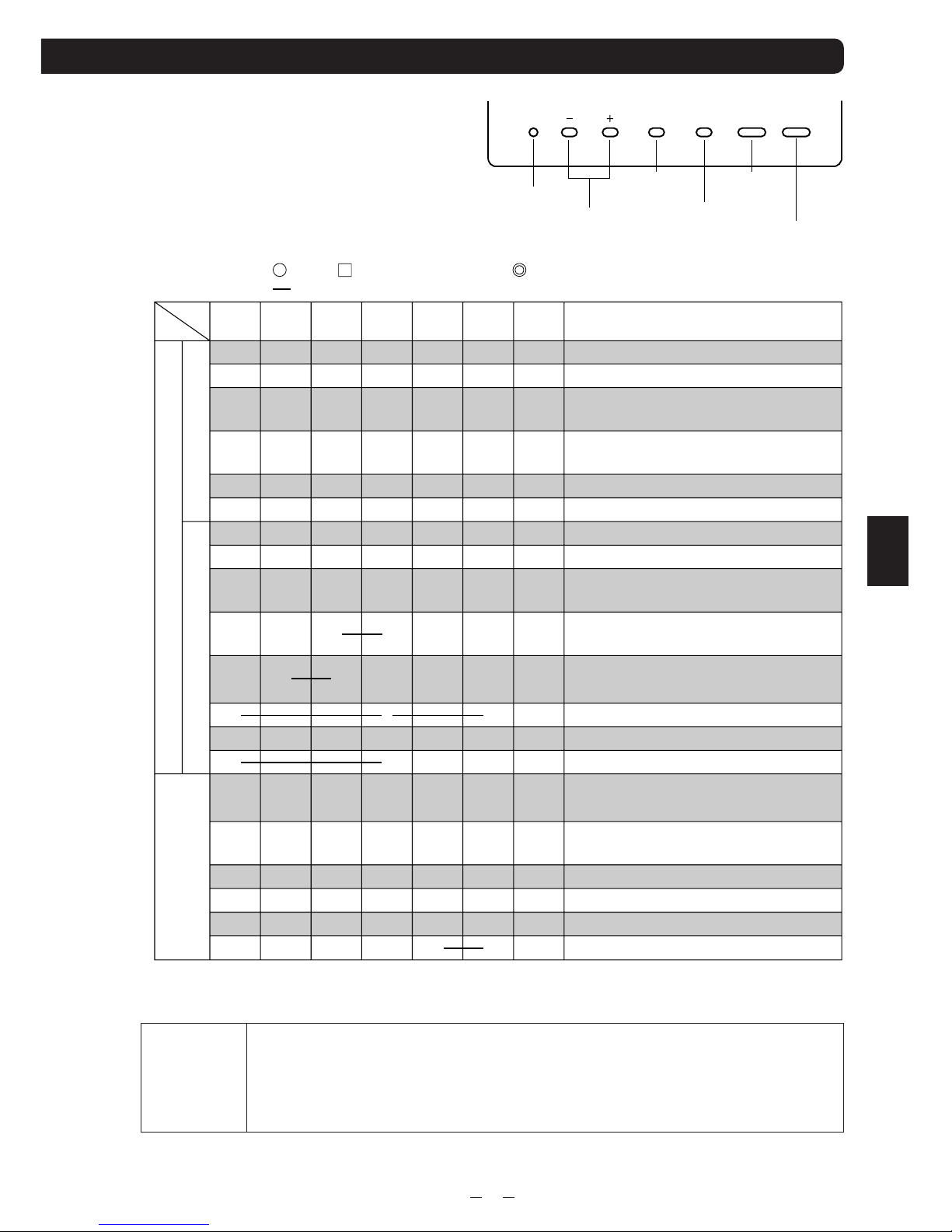
2. Display and key functions ................................................................................................................................... 8
3. Function modes ................................................................................................................................................ 10
4. Set-up
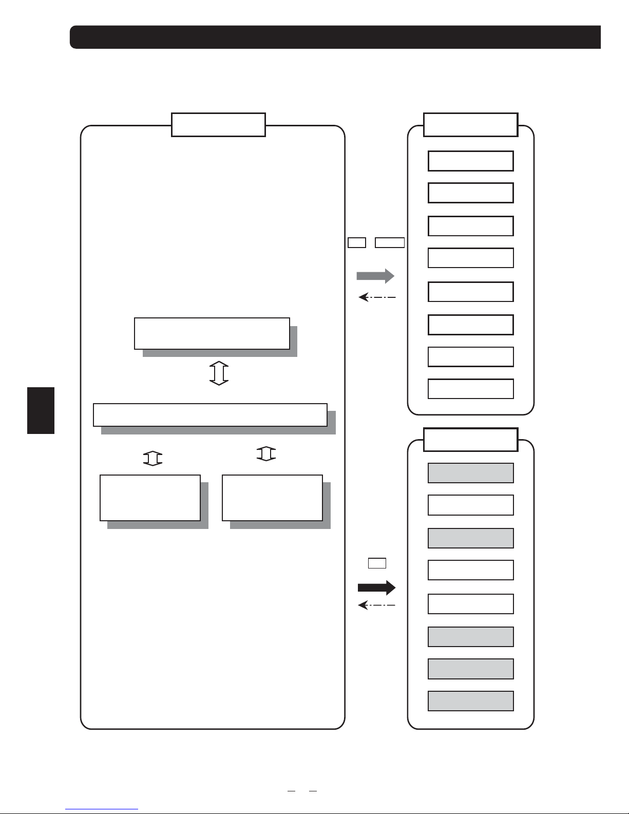
4.1 Set-up Diagram ........................................................................................................................................... 12
4.2 Menu 1 : Basic Set-up ................................................................................................................................. 14
4.3 Menu 2 : Model code, LCD and Backlight Set-up ..................................................................................... 17
4.4 Menu 3 : Bar graph, Unit, Expanded Counting, Harmonics Set-up ........................................................... 18
4.5 Menu 4 : Index Indicator Set-up ................................................................................................................. 20
4.6 Menu 5 : Alarm Set-up ................................................................................................................................ 21
4.7 Menu 6 : Analog output, Pulse output set-up .............................................................................................. 23
4.8 Menu 7 : Communication Set-up (ME110NSR-C) .................................................................................... 26
4.9 Menu 7 : Communication Set-up (ME110NSR-MB) ................................................................................. 27
4.10 Menu 8 : Alarm output Test ...................................................................................................................... 28
5. Operation
5.1 Display Change ........................................................................................................................................... 30
5.2 Phase Change .............................................................................................................................................. 30
5.3 Bar Graph Display ...................................................................................................................................... 31
5.4 Indicator ...................................................................................................................................................... 31
5.5 Maximum Value and Minimum Value Display ........................................................................................... 32
5.6 Cyclic Display Change ............................................................................................................................... 33
5.7 Alarm Display and How to cancel .............................................................................................................. 34
5.8 Harmonics Display ..................................................................................................................................... 35
5.9 Expanded Counting Display ....................................................................................................................... 36
5.10 Set Value Confirmation Mode ................................................................................................................... 37
6. Others
6.1 How to rearrange the Display Pattern (P00) ............................................................................................... 38
6.2 Display Pattern Contents ............................................................................................................................ 40
6.3 Maximum Scale Value ................................................................................................................................ 41
6.4 Maximum Scale Table ................................................................................................................................ 42
6.5 Measurement Characteristic ....................................................................................................................... 44
6.6 Troubleshooting .......................................................................................................................................... 45
1. Dimensions ........................................................................................................................................................ 46
2. Mounting ........................................................................................................................................................... 48
3. Wiring ................................................................................................................................................................ 49
4. Wiring Diagram ................................................................................................................................................. 50
Specifications ........................................................................................................................................................ 52
Communication Specifications .............................................................................................................................. 53
Set-up table ............................................................................................................................................................ 54
Example of Simple Set-up ..................................................................................................................................... 56
Operation
Installation
Contents
Example of Simple Set-up
Specification

4
(Always read these instructions before using this equipment)
For personnel and product safety please read the contents of these operating instructions
carefully before using.
Please save this manual to make it accessible when required and always forward it to the end user.
Indicates that incorrect handling may cause hazardous conditions.
Always follow the instructions because they are important to personal safety.
Otherwise, it could result in electric shock, fire, erroneous operation,
and damage of the instrument.
■Normal service conditions
CAUTION
Safety
precaution
Conditions
Below 600V, or 600A power lines
Other power lines
Length
30cm or more
60cm or more
CAUTION
Use the instrument in an environment that meets the Normal service conditions as following points:
●Ambient temperature :-5 to 50°C, average day temperature exceeds 35°C
●Humidity :30~85%RH, non condensing.
●Altitude: 1000m or less
●Pollution Degree : 2
●Atmosphere without corrosive gas, dust, salt, oil mist.
●A place without excessive shocks or vibration.
●Do not expose to rain and water drips.
●Do not expose to direct sunlight.
●An area in where are no pieces of metal and an inductive substance disperse.
●Do not expose to strong electromagnetic field and ambient noises.
CAUTION
●This instrument should be installed and used by a qualified electrician.
●The instrument must not be powered and used until its definitive assembly on the cabinet's door.
●Ve r ity the following points;
Auxiliary power supply and Measuring ratings
Current circuits, C1, C2 and C3 are Measurement category 1.
Voltage circuits, P1, P2 and P3 are Measurement category 3.
●The instrument is to be mounted on panel. All connections keep inside the cabinet.
●Tighten the terminal screws with the specified torque and use the suitable pressure connectors
and suitable wire size. (see page 49)
●When wiring in the instrument, be sure that it is done correctly by checking the instrument ‘s
wiring diagrams. (see page 50,51)
●Be sure there are no foreign substances such as sawdust or wiring debris inside the instrument.
●Do not drop this instrument from high place. If you drop it and the display is cracked, do not touch
the liquid crystal and or get it in your mouth. When touch the liquid crystal, wash it away at once.
●In order to prevent invasion of noise, do not bunch the control wires or communication cables
with the main circuit or power wire, or install them close to each other.
Keep the distance between communicational signal lines, input signal lines and power lines,
high voltage lines are shown below, when run parallel to each other.
■Installation instructions
Auxiliary power supply 100-240V AC
+10-15
%(50-60Hz) 14VA
100V DC
+40-25
% 6W
Ratings Voltage
Current
Frequency
254V AC phase-neutral / 440V AC phase-phase
5A (via current transformer)
50/60Hz
Safety precaution

5
●Wipe dirt on surface with a soft dry cloth.
●Check the following points,
Condition of the apepearance
Condition of the Display
Unusual sound, a smell, and generation of heat
Condition of the wiring and the attachment
■Storage conditions
●Ambient temperature the :-20 to 60°C, average day temperature exceeds 35°C
●Humidity range 30~85%RH, non condensing.
●Atmosphere without corrosive gas, dust, salt, oil mist.
●A place without excessive shocks or vibration.
●Do not expose to rain and water drips.
●Do not expose to direct sunlight.
●An area in where are pieces of metal and an inductive substance disperse.
■Disposal
●When disposing of this product , treat it as industrial waste..
●The battery is not used for this product.
■Guarantee
The period of guarantee is for 1 year from the sale date, except in the case that the failure has been caused by bad
handling of the product, provided that it has been installed according to the manufacture's instructions.
■Operation instructions
CAUTION
●When the external terminals are connected to the external equipments, the instrument and the exter-
nal equipments must not be powered and used until its definitive assembly on the cabinet's door.
●The rating of the terminal of the external equipment should satisfy the rating of the external
terminal of this instrument. (See Specifications.)
■Maintenance instructions
CAUTION
●Do not touch the terminals while all the circuits connected to this instrument are alive.
●Do not disassemble or modify the instrument.
●Do not contact a chemical dust cloth contact the instrument for a long time, or do not wipe it
with benzene, thinner, alcohol.
Safety
precaution

6
This section summarizes the precautions on conformance to the EMC Directive of the cabinet con-
structed using this Instrument.
However, the method of conformance to the EMC Directive and the judgment on whether or not the cabinet con-
forms to the EMC Directive has to be determined finally by the manufacturer.
1. EMC Standards
The standards applicable to the EMC Directive ( No.89/336/EEC ) are listed below.
(1) Radiated radio frequency emission ----------------------------------- EN61000-6-4/2001
(2) Radiated radio frequency electromagnetic field immunity ------EN61000-6-2/2001
2. Installation (EMC directive)
The instrument is to be mounted on panel of a cabinet.
Therefore, the construction of a cabinet is important not only for safety but also for EMC.
The instrument is examined by the following conditions.
●Use a conductive cabinet.
●Six faces of a cabinet have to be ensured conductivity for each other.
●A cabinet has to be connected to earth by a thick wire of low impedance.
●Holes on faces of cabinet have to be 10 cm or less in diameter.
●The terminals for protective earth and functional earth have to be connected to earth by a thick wire of low
impedance. (A terminal for protective earth is important not only for safety but also for EMC.)
●All connections keep inside the cabinet.
●Wirings outside the cabinet have to be used with the shielded cable.
The following diagram shows how to provide good contact of the shielded cable.
Remove part of the outer cover.
Remove part of the paint musk on the cabinet.
Connect those parts with the clamp.
Protective earth: Maintains the safety of the instrument and improves the noise resistance.
Functional earth: Improves the noise resistance.
Shield section
Paint mask
Shielded cable
Screw
Clamp fitting
Safety
precaution
EMC DIRECTIVE INSTRUCTION

7
The ME110NSR series is an instrument for measuring and metering electrical values for three-phase
LV/HV electrical networks.
■Various measurement parameters
■4 measurement items appear on one display
By combination of bar graph and digital 3-stage display, 4 measurement items can be displayed on one
display. For example, Voltage, current, power factor and active power can be displayed at the same time.
■RS485 interface, ModBus RTU(ME110NSR-MB)
■CC-Link communication
Measured values can be sent to PC or PLC via CC-Link communications. (ME110NSR-C)
■Analog 4 outputs + pulse output + alarm relay output (ME110NSR-4APH)
For example, the analog outputs of voltage, current, active power, and power factor, the pulse output of active
energy, and the alarm output of THD can be performed by one unit.
■Harmonics
It is equipped with harmonics current and harmonics voltage measurement function as standard one.
■Back light auto off function
It is equipped with energy saving mode function where the back light is turned off when there is no key
operation for 5 minutes.
1. Features
Current
Current demand
Voltage
Active power
Active power demand
Reactive power
Apparent power
Power facter
Frequency
Current
Harmonics
Voltage
Harmonics
Active energy
Reactive energy
It is refer to the followings in this manual,
average value : avg
three phase total RMS : Σ
phase to phase : L-L
phase to neutral : L-N
ex) average value of current : A
avg
Three phase active power : ΣW
1-phase to 2-phase voltage : V12
1-phase to neutral voltage : V1N
A
DA
V
W
DW
var
VA
cosφ
Hz
HI
HV
Wh
varh
A1, A2, A3, AN, A
avg
DA1, DA2, DA3, DAN, DA
avg
V12, V23, V31 or V1N, V2N, V3N, V
avg
ΣW, W1, W2, W3
ΣDW, DW1, DW2, DW3
Σvar, var1, var2, var3
ΣVA, VA1, VA2, VA3
ΣPF, PF1, PF2, PF3
Hz
HI1,HI2, HI3, HIN
THD, h1, h3, h5, h7, h9, h11, h13
HV1N, HV2N, HV3N, THD
THD, h1, h3, h5, h7, h9, h11, h13
Imported, Exported
Imported, Exported, Capacitive, Inductive
Measuement parameters Maximum
value
,
,
–
,
–
–
–
–
,
Minimum
value
Features

8
2. Display and Key functions
N1
HARMONICS
1
10
5
5
8
9
16
13 14 15 12
7
4
3612
11
ALARM
HI
LO
SET
COM
1
2
3
4
5
6
7
8
9
10
11
12
13
14
15
16
Harmonics
LEAD status
LAG status
Scale of the bar graph
Outside range
Index indicator
Alarm indicator
Bar graph status
Phase status
Unit
Multiplying factor
Metering status
Setup mode status
Alarm status
Communication status
Digital
It means that the digital displays are harmonics values.
They show direction of Power Factor or Reactive Power on bar graph.
They show the type of counting of Reactive Energy on Reactive Energy Display.
They show the scales of the bar graph.
Measurement value is outside range of scale of the bar graph.
It appears on the bar graph by setting up in SETUP MODE.
The value of index can be set up to each of a maximum of 4 items.
It appears on the bar graph by setting up in SETUP MODE.
The value of alarm can be set up to each of a maximum of 4 items.
They show the item expressed with the bar graph.
They show the phase for each of the digital displays.
When there is no display, it means Average or Σ.
They show the unit for each of the digital displays.
It shows the multiplying factor for calculating energy.
When it is blinking, the instrument is counting active energy.
It appears at SETUP MODE and Set Value Confirmation MODE.
They show that the upper limit value or lower limit value was exceeded.
It shows that the instrument is equipped with a communication function.
It blinks under the condition of a communication error.
The measured value is displayed in a digital number.
■Display
Note: The above display is an example for explanation.
Display

9
SET RESET MAX/MIN PHASE DISPLAY
○
○
○
○
○ ○
○ ○
◎
◎
◎
◎ ◎
◎ ◎
◎ ◎ ◎
◎
◎ ◎
○
○ ○
○
□
◎
□ □
■Functions of operation key
Theoperationkeyhavevariousfunctions
accordingtohowtheyarepresseddown.
Meaning of code : (press), (press on over 1 second), (press on over 2 seconds),
(press simultaneously)
Setkey
Resetkey
+/–key Maximum/minimum
key
Phasechange
key
Displaychange
key
SET – +
RESET
Max/Min
PHASE
DISPLAY
Function
Display changes.
Phase changes.
Mode changes to the max./min. display and
the instantaneous display.
An alarm condition is canceled.
(Effective in alarm hold condition.)
The item expressed with the bar graph is changed.
Harmonics number changes at harmonics display.
The displays changes cyclically.
The phases changes cyclically.
Maximum values and minimum values on the
display are reset to the present value.
All of the Maximum values and minimum
values are reset to the present value.
The counting values of three digits of low rank are
displayed. After pressing once again, the display returns.
All of the counting values are zero reset.
The display of Set value confirmation mode appears.
The display of Setup mode appears.
The set-up items are saved, and set-up item is
changed to next item.
The values of set-up is changed.
(If it presses for 1 sec or more fast forward or fast return.)
Back to the previous item.
Back to the Setup display.
It is for Alarm test. (Effective in Menu 8)
The instrument is reset. (Effective in CANCEL display.)
While the back light is off, if the operation key is pressed, the back light is always lit. If the operation button is pressed once again,
the function in the above table appears.
Note:
Operation mode
BASICSpecial
Setting mode/
Set value
confirmation mode
●If the function of “maximum value and minimum value reset” and “Wh, varh
zero reset” are done, data will be lost. Before the operation, record data.
●If the function of “meter restart” is done, the entire measurement (measure-
ment display, alarm, analog output, pulse) stops.
Notes
Key functions

10
3. Function modes
■Diagram of Each Mode
This meter has 3 kinds of function modes. Use it at each mode according to your requirements.
Instantaneous value display
Maximum value and minimum
value display
Cyclic display
change
Cyclic phase
change
Set-up Menu 1
Set-up Menu 2
Set-up Menu 3
Set-up Menu 4
Set-up Menu 5
Set-up Menu 6
Set-up Menu 7
Set-up Menu 8
Set-up Menu 1
Set-up Menu 2
Set-up Menu 3
Set-up Menu 4
Set-up Menu 5
Set-up Menu 6
Set-up Menu 7
Set-up mode
Set value confirmation mode
Pressing
simultaneously
for 2 seconds
SET + RESET
Pressing
2 seconds
Operation mode
Set-up Menu 8
Shaded set menus of the set value confirmation mode are only for confirming set values,
and their settings cannot be changed.
Note:
SET
Modes

11
■Outline of Function Mode
Operation mode
Measuring and displaying in this mode.
Instantaneous value display
The instantaneous values of the set-up display pattern are displayed. Usually, this display is used.
Maximum value and minimum value display
The maximum values and minimum values are displayed. (see page 32)
Cyclic display change
Displays are automatically changed at every 5 seconds. (see page 33)
Cyclic phase change
Phases are automatically changed at every 5 seconds. (see page 33)
Set-up mode
In this mode, all the setting items including primary voltage, primary current, and so forth can be set.
Set necessary items before operation. (see pages 12 - 29)
Set value confirmation mode
This mode is for checking the contents of the set-up items.
In this mode, the contents of the basic set-up items are protected from changing accidentally.
Index indicator set-up, alarm set-up, LCD and backlight set-up and so forth can be changed.
(see page 37)
Modes

12
SET
4.1 Set-up Diagram
Phase
display
Display
pattern
Useing VT/
direct input
Direct
voltage
Secondary
voltage
Primary
voltage
Vo ltage unit
V/kV
Primary
current
Current unit
A/kA
Time constant for
active power demand
Time constant for
current demand
Model
code
LCD
contrast
Back light
brightness
Back light
auto off
Current
maximum scale
Active
power maximum
scale
Active power
scale type
Reactive power
maximum scale
Expanded
counting
Active
power unit
W/kW/MW
Reactive
power unit
Harmonics
Operation mode
Set-up menu
End
End
display
Cancel
display
Set-up menu 1 (basic set-up)
Set-up menu 2 Set-up menu 3
(Example of set-up mode)
In the set-up mode “ ” is lit.
LEAD
LAG
%
高調波
サーマル
NRSTRN
NRSTRN
Hz
Hz
2
1
3
テ マント
最小大
cos
cos
次
分秒
%
var
VA
NRSTRN
Hz
2
1
3
テ マント
最小大
cos
var
VA
NRSTRN
Hz
2
1
3
テ マント
最小大
cos
10000
varh
h
VA
警報
漏電
下限
通信
上限
The changed contents are canceled.
The changed contents
are saved and performed.
1Press the key and the key simultaneously for
2 seconds to get in the set-up mode.
2Select a set-up menu number by or key.
3
Change the contents in each set-up menu. (Refer to pages 22 - 27.)
4After completion of set-up, select ‘End’ in the set-up menu
and press the key.
5When the End display appears, press the key once
again.
SET
✽1
✽1
✽1
✽1
✽1
✽1
✽1
✽1
✽1: They may not display
by the content of the set-up item.
Examples of set-up mode and set value
confirmation mode
• How to access the set-up items.
+ –
SET
RESET
SET
SET
10000
設定 警報
漏電
下限
通信
上限
LEAD
LAG
%
高調波
サーマル
NRSTRN
NRSTRN
Hz
Hz
2
1
3
テ マント
最小大
cos
cos
次
分秒
%
var
VA
NRSTRN
Hz
2
1
3
テ マント
最小大
cos
var
VA
NRSTRN
Hz
2
1
3
テ マント
最小大
cos
varh
h
VA
LEAD
LAG
%
高調波
サーマル
NRSTRN
NRSTRN
Hz
Hz
2
1
3
テ マント
最小大
cos
cos
次
分秒
%
var
VA
NRSTRN
Hz
2
1
3
テ マント
最小大
cos
var
VA
NRSTRN
Hz
2
1
3
テ マント
最小大
cos
10000
varh
h
VA
警報
漏電
下限
通信
上限
LEAD
LAG
%
高調波
サーマル
NRSTRN
NRSTRN
Hz
Hz
2
1
3
テ マント
最小大
cos
cos
次
分秒
%
var
VA
NRSTRN
Hz
2
1
3
テ マント
最小大
cos
var
VA
NRSTRN
Hz
2
1
3
テ マント
最小大
cos
10000
varh
h
VA
警報
漏電
下限
通信
上限
LEAD
LAG
%
高調波
サーマル
NRSTRN
NRSTRN
Hz
Hz
2
1
3
テ マント
最小大
cos
cos
次
分秒
%
var
VA
NRSTRN
Hz
2
1
3
テ マント
最小大
cos
var
VA
NRSTRN
Hz
2
1
3
テ マント
最小大
cos
10000
varh
h
VA
警報
漏電
下限
通信
上限
LEAD
LAG
%
高調波
サーマル
NRSTRN
NRSTRN
Hz
Hz
2
1
3
テ マント
最小大
cos
cos
次
分秒
%
var
VA
NRSTRN
Hz
2
1
3
テ マント
最小大
cos
var
VA
NRSTRN
Hz
2
1
3
SET
テ マント
最小大
cos
10000
varh
h
VA
警報
漏電
下限
通信
上限
LEAD
LAG
%
高調波
サーマル
NRSTRN
NRSTRN
Hz
Hz
2
1
3
テ マント
最小大
cos
cos
次
分秒
%
var
VA
NRSTRN
Hz
2
1
3
テ マント
最小大
cos
var
VA
NRSTRN
Hz
2
1
3
テ マント
最小大
cos
10000
varh
h
VA
警報
漏電
下限
通信
上限
LEAD
LAG
%
高調波
サーマル
NRSTRN
NRSTRN
Hz
Hz
2
1
3
テ マント
最小大
cos
cos
次
分秒
%
var
VA
NRSTRN
Hz
2
1
3
テ マント
最小大
cos
var
VA
NRSTRN
Hz
2
1
3
テ マント
最小大
cos
10000
varh
h
VA
SET
警報
漏電
下限
通信
上限
SET SET
SET
SET
4. Set-up
1.
The initial contents are shown to page56.
Note

13
SET
Indicator
item 1
Indicator
value 1
Alarm item
ModBus
baud rates
ModBus
parity
ModBus
stop bit
Alarm value
Indicator
item 2
Indicator
value 2
Indicator
item 3
Indicator
value 3
Indicator
item 4
Indicator
value 4
Analog
output 1
Analog
output 2
Analog
output 3
Analog
output 4
Pulse
output
Alarm
output test
Alarm cancel
method
Alarm delay
time
Action
Shift from the operation mode to the set-up mode.
Select the menu number to set or “End”.
Go back to the previous setting item.
Select a set value.
Shift to the End screen.
Select “CANCEL”.
Cancel the setting.
Skip remaining setting items during setting.
Key operation
Press it for 2 seconds.
Press it several times.
Press it.
Press it.
Press it several times.
Press it.
Press it.
Press it.
Press it.
Press it for 1 second.
+
or
or
or
Omitted in
figure
Arrow in
figure
Set-up mode or set value confirmation mode
Set-up menu 4
✽
2
✽2
✽2
✽2
✽2
✽2
✽2: They may not display by the model.
✽2
Set-up menu 5 Set-up menu 6 Set-up menu 8Set-up menu 7
(Example of set value confirmation mode)
LEAD
LAG
%
高調波
サーマル
NRSTRN
NRSTRN
Hz
Hz
2
1
3
テ マント
最小大
cos
cos
次
分秒
%
var
VA
NRSTRN
Hz
2
1
3
テ マント
最小大
cos
var
VA
NRSTRN
Hz
2
1
3
テ マント
最小大
cos
10000
varh
h
VA
警報
漏電
下限
通信
上限
Shift from the operation mode to the set
value confirmation mode.
Get into each setting screen. Shift to the
next setting item.
Memorize the setting contents, and go
back to the operation mode.
Press them simultaneously
for 2 seconds.
SET
✽2
✽2
✽2
✽2
✽2
CC-Link
station
number
CC-Link
baud rates
ModBus
address
CC-Link
module
reset
ModBus
module
reset
✽2
✽2
✽2
(ME110NSR-C)
(ME110NSR-MB)
+
+
SET
SET
SET
SET
SET
SET
SET
+–
–
–
RESET
DISPLAY
LEAD
LAG
%
高調波
サーマル
NRSTRN
NRSTRN
Hz
Hz
2
1
3
テ マント
最小大
cos
cos
次
分秒
%
var
VA
NRSTRN
Hz
2
1
3
テ マント
最小大
cos
var
VA
NRSTRN
Hz
2
1
3
テ マント
最小大
cos
10000
varh
h
VA
警報
漏電
下限
通信
上限
LEAD
LAG
%
高調波
サーマル
NRSTRN
NRSTRN
Hz
Hz
2
1
3
テ マント
最小大
cos
cos
次
分秒
%
var
VA
NRSTRN
Hz
2
1
3
テ マント
最小大
cos
var
VA
NRSTRN
Hz
2
1
3
テ マント
最小大
cos
10000
varh
h
VA
警報
漏電
下限
通信
上限
LEAD
LAG
%
高調波
サーマル
NRSTRN
NRSTRN
Hz
Hz
2
1
3
テ マント
最小大
cos
cos
次
分秒
%
var
VA
NRSTRN
Hz
2
1
3
テ マント
最小大
cos
var
VA
NRSTRN
Hz
2
1
3
テ マント
最小大
cos
10000
varh
h
VA
警報
漏電
下限
通信
上限
LEAD
LAG
%
高調波
サーマル
NRSTRN
NRSTRN
Hz
Hz
2
1
3
テ マント
最小大
cos
cos
次
分秒
%
var
VA
NRSTRN
Hz
2
1
3
テ マント
最小大
cos
var
VA
NRSTRN
Hz
2
1
3
テ マント
最小大
cos
10000
varh
h
VA
警報
漏電
下限
通信
上限
LEAD
LAG
%
高調波
サーマル
NRSTRN
NRSTRN
Hz
Hz
2
1
3
テ マント
最小大
cos
cos
次
分秒
%
var
VA
NRSTRN
Hz
2
1
3
テ マント
最小大
cos
var
VA
NRSTRN
Hz
2
1
3
テ マント
最小大
cos
10000
varh
h
VA
警報
漏電
下限
通信
上限
SET SET SET SET SET

14
SET
Set-up menu
1Phase display
2Display Pattern
3Useing VT /
direct input
+–
,
Set the set-up menu number to “1”. (Set as shown in the right
display.)
1In voltage display, set the phase display “phase to neutral” or “phase
to phase”.
Phase to neutral
Phase to phase
L-n
L-L
:
:
2Set-up the display pattern.
3Set-up the using VT or direct input (without VT).
Note: As for detailed display patterns, refer to page 38.
: Display is made at this display setting.
: Set by the set-up menu 3. (page 19)
:
Select “P00”, and set display sequence and display position. (page 36)
HI : harmonic current, HV : harmonic voltage, DA : current demand,
DW : active power demand
YES
no
P01
P02
P03
P04
P05
P06
P07
P08
P09
P10
P11
P12
P13
P00
AA
N
DA
DA
N
VWDW
cosf
var VA Hz Wh
varh
HI HV
Display
pattern
Wh
Exported
active
energy
varh
Special
4Direct voltage
4Set-up the rated voltage for soaling of the bar graph.
(phase to neutral / phase to phase)
63.5V/110V
110V/190V
220V/380V
240V/415V
254V/440V
+–
,
+–
,
+–
,
+–
,
SET
DISPLAY
SET
DISPLAY
SET
DISPLAY
SET
DISPLAY
SET
DISPLAY
: useing VT
: direct input
If you set “Yes” on set up No.3, this display does not appear.
LEAD
LAG
%
高調波
サーマル
NRSTRN
NRSTRN
Hz
Hz
2
1
3
テ マント
最小大
cos
cos
次
分秒
%
var
VA
NRSTRN
Hz
2
1
3
テ マント
最小大
cos
var
VA
NRSTRN
Hz
2
1
3
テ マント
最小大
cos
10000
varh
h
VA
警報
漏電 下限
通信
上限
LEAD
LAG
%
高調波
サーマル
NRSTRN
NRSTRN
Hz
Hz
2
1
3
テ マント
最小大
cos
cos
次
分秒
%
var
VA
NRSTRN
Hz
2
1
3
テ マント
最小大
cos
var
VA
NRSTRN
Hz
2
1
3
テ マント
最小大
cos
10000
varh
h
VA
警報
漏電 下限
通信
上限
LEAD
LAG
%
高調波
サーマル
NRSTRN
NRSTRN
Hz
Hz
2
1
3
テ マント
最小大
cos
cos
次
分秒
%
var
VA
NRSTRN
Hz
2
1
3
テ マント
最小大
cos
var
VA
NRSTRN
Hz
2
1
3
テ マント
最小大
cos
10000
varh
h
VA
警報
漏電 下限
通信
上限
LEAD
LAG
%
高調波
サーマル
NRSTRN
NRSTRN
Hz
Hz
2
1
3
テ マント
最小大
cos
cos
次
分秒
%
var
VA
NRSTRN
Hz
2
1
3
テ マント
最小大
cos
var
VA
NRSTRN
Hz
2
1
3
テ マント
最小大
cos
10000
varh
h
VA
警報
漏電 下限
通信
上限
LEAD
LAG
%
高調波
サーマル
NRSTRN
NRSTRN
Hz
Hz
2
1
3
テ マント
最小大
cos
cos
次
分秒
%
var
VA
NRSTRN
Hz
2
1
3
テ マント
最小大
cos
var
VA
NRSTRN
Hz
2
1
3
テ マント
最小大
cos
10000
varh
h
VA
警報
漏電 下限
通信
上限
SET
SET
SET
SET
SET
In this set-up menu 1, set-up the basic contents as following for correct measurement .
In the operation mode, after pressing the
SET
and the
RESET
simultaneously for 2 seconds or more, the following
operation becomes available. An underline shows an initial value.
4.2 Set-up Menu 1
4. Set-up

15
SET
•
•
•
•
✽
•
•
•
•
•
✽
•
6Primary voltage
7Vo ltage unit
Sets the primary voltage value (phase to neutral) of VT in the case of useing VT. (The
initial value is 240V.)
When the set value of primary voltage is in the range of
1000V - 6600V, unit can be selected.
5VT secondary
voltage
Sets the secondary voltage values of VT in the case of useing VT.
(phase to neutral / phase to phase)
63.5V/110V
100V/173V
110V/190V
115V/199V
120V/208V
From top digit, select the value of the flickering digit by and .
The setting digit can be moved to right by the SET .
The setting digit can be moved to left by the DISPLAY .
The number of settable digits is 3 digits. Setting is available in the range from 60V to 750kV. (750000V)
If it is set to other range than 60V - 750kV, error display (E05) appears. At the moment of the error
display, press the SET , and review the set value, and set it once again.
When the SET is pressed at the most lower digit, the setting item goes to the next one.
Primary voltage (phase to phase)
=primary voltage × 1.73
(phase to neutral)
The primary voltage (phase to neutral)
VkV
8Primary current
9Current unit
8Sets the primary current value of CT. (The initial value is 5A.)
When the set value of primary currnet is in the range of
980A - 8400A, measure can be selected.
AkA
To be continued
to the next page
+–
5
6
7
9
From top digit, select the value of the flickering digit by and .
The setting digit can be moved to right by the SET .
The setting digit can be moved to left by the DIAPLAY .
The number of settable digits is significant 2 digits. Setting is available in the range from 5A to 30kA (30000A).
If it is set to other range than 5A - 30kA, error display (E05) appears. At the moment of the error
display, press the SET , and review the set value, and set it once again.
When the SET is pressed at the most lower digit, the setting item goes to the next one.
+–
+–
,
+–
,
+–
,
+–
,
+–
,
SET
DISPLAY
SET
DISPLAY
SET
DISPLAY
SET
DISPLAY
SET
DISPLAY
If you set the primary voltage out of 1000V-6600V on No.6, this
display does not appear.
If you set the value of primary current out of 980A-8400A on No.8,
this display does not appear.
If you set “no” on set up No.3, this display does not appear.
SET
DISPLAY
SET
DISPLAY
If you set “no” on set up No.3, this display does not appear.
If you set as “phase to phase” on set up No.1, voltage measurement is calculated below.
If you set “no” on set up No.3, this display does not appear.
the primary phase to neutral voltage
the secondary phase to neutral voltage
(voltage value) = (secondary phase to phase voltage) ×
LEAD
LAG
%
高調波
サーマル
NRSTRN
NRSTRN
Hz
Hz
2
1
3
テ マント
最小大
cos
cos
次
分秒
%
var
VA
NRSTRN
Hz
2
1
3
テ マント
最小大
cos
var
VA
NRSTRN
Hz
2
1
3
テ マント
最小大
cos
10000
varh
h
VA
SET
警報
漏電 下限
通信
上限
LEAD
LAG
%
高調波
サーマル
NRSTRN
NRSTRN
Hz
Hz
2
1
3
テ マント
最小大
cos
cos
次
分秒
%
var
VA
NRSTRN
Hz
2
1
3
テ マント
最小大
cos
var
VA
NRSTRN
Hz
2
1
3
テ マント
最小大
cos
10000
varh
h
VA
SET
警報
漏電 下限
通信
上限
LEAD
LAG
%
高調波
サーマル
NRSTRN
NRSTRN
Hz
Hz
2
1
3
テ マント
最小大
cos
cos
次
分秒
%
var
VA
NRSTRN
Hz
2
1
3
テ マント
最小大
cos
var
VA
NRSTRN
Hz
2
1
3
テ マント
最小大
cos
10000
varh
h
VA
SET
警報
漏電 下限
通信
上限
LEAD
LAG
%
高調波
サーマル
NRSTRN
NRSTRN
Hz
Hz
2
1
3
テ マント
最小大
cos
cos
次
分秒
%
var
VA
NRSTRN
Hz
2
1
3
テ マント
最小大
cos
var
VA
NRSTRN
Hz
2
1
3
テ マント
最小大
cos
10000
varh
h
VA
SET
警報
漏電 下限
通信
上限
LEAD
LAG
%
高調波
サーマル
NRSTRN
NRSTRN
Hz
Hz
2
1
3
テ マント
最小大
cos
cos
次
分秒
%
var
VA
NRSTRN
Hz
2
1
3
テ マント
最小大
cos
var
VA
NRSTRN
Hz
2
1
3
テ マント
最小大
cos
10000
varh
h
VA
SET
警報
漏電 下限
通信
上限
Set-up Menu 1 (basic set-up)

16
SET
!0 Time constant for
Active power demand
!1 Time constant
for current demand
Set-up menu
According to the set-up diagram (page 12), save the changed
contents, or continue to the other set-up menu.
!0 Set up the time constant for calculating active power demand.
0 second
10 seconds
20 seconds
30 seconds
40 seconds
50 seconds
1 minute
2 minutes
3 minutes
4 minutes
5 minutes
6 minutes
7 minutes
8 minutes
9 minutes
10 minutes
15 minutes
20 minutes
25 minutes
30 minutes
Note) Even when the display pattern not display the active power demand, this screen appears. If the active power
demand is not necessary, press the SET as it is.
!1 Set up the time constant for calculating current demmand.
0 second
10 seconds
20 seconds
30 seconds
40 seconds
50 seconds
1 minute
2 minutes
3 minutes
4 minutes
5 minutes
6 minutes
7 minutes
8 minutes
9 minutes
10 minutes
15 minutes
20 minutes
25 minutes
30 minutes
From previous page
Note) Even when the display pattern not display the current demand, this screen appears. If the current demand is
not necessary, press the SET as it is.
+–
,
+–
,
+–
,
SET
DISPLAY
SET
DISPLAY
SET
LEAD
LAG
%
高調波
サーマル
NRSTRN
NRSTRN
Hz
Hz
2
1
3
テ マント
最小大
cos
cos
次
分秒
%
var
VA
NRSTRN
Hz
2
1
3
テ マント
最小大
cos
var
VA
NRSTRN
Hz
2
1
3
テ マント
最小大
cos
10000
varh
h
VA
SET
警報
漏電
下限
通信
上限
LEAD
LAG
%
高調波
サーマル
NRSTRN
NRSTRN
Hz
Hz
2
1
3
テ マント
最小大
cos
cos
次
min
S%
var
VA
NRSTRN
Hz
2
1
3
テ マント
最小大
cos
var
VA
NRSTRN
Hz
2
1
最小大
cos
10000
varh
h
VA
SET
警報
漏電
下限
通信
上限
LEAD
LAG
%
高調波
サーマル
NRSTRN
NRSTRN
Hz
Hz
2
1
3
テ マント
最小大
cos
cos
次
var
VA
NRSTRN
Hz
2
1
3
テ マント
最小大
cos
var
VA
NRSTRN
Hz
2
1
最小大
cos
10000
varh
h
VA
SET
警報
漏電
下限
通信
上限
DEMAN D
DEMAN D
min
S%
4. Set-up
In the case of use only by the set-up menu 1 (basic set-up), go to “5. Operation” in page 30.
In the case to use additional functions, go to “Set-up Menus 2 - 8” in page 17 - 28.
Set-up Menu 1 (basic set-up) continued
If the contents in the set-up menu 1 are changed, the maximum value, minimum
value, demand value of related measurement items will be reset. (However, all of
the counting values are not reset.)
Note

17
SET
Set-up menu
Set-up menu
1Model code
3Back light
brightness
2LCD contrast
4Back light
ON/OFF setting
Set the set-up menu number to “2”. (Set as shown in the right
screen.)
According to the set-up diagram (page 12), save the changed
contents, or continue to the other set-up menu.
1Type display (This is only display, and settings cannot be
changed.)
Model type
• ME110NSR
• ME110NSR-4APH
• ME110NSR-4A2P
• ME110NSR-C
• ME110NSR-MB
Display
non
4APH
4A2P
CC
485
2Set the LCD contrast. ‘1’ is the weakest contrast. (This set-up
is normally unnecessary.)
3Set the back light brightness. 5 is the brightest setting. (Setting
this is normally unnecessary.)
4Set the back light auto off (Auto) / continuous on (Hold).
(Setting this is normally unnecessary.)
If you set to ‘Auto off’, the backlight turn off when there is no
key operation for 5 minutes. When an operation key is pressed,
it is lit for 5 minutes. At this moment, the display is not changed.
When the operation key is pressed once again, the display is
changed.
Auto
(Auto OFF)
HoLd
(Continuous ON)
1 2 3 4 5
1 2 3 4 5
............................
................
.....................
.................
........................
+–
,
+–
,
+–
,
+–
,
+–
,
+–
,
SET
DISPLAY
SET
DISPLAY
SET
DISPLAY
SET
DISPLAY
SET
LEAD
LAG
%
高調波
サーマル
NRSTRN
NRSTRN
Hz
Hz
2
1
3
テ マント
最小大
cos
cos
次
分秒
%
var
VA
NRSTRN
Hz
2
1
3
テ マント
最小大
cos
var
VA
NRSTRN
Hz
2
1
3
テ マント
最小大
cos
10000
varh
h
VA
SET
警報
漏電
下限
通信
上限
LEAD
LAG
%
高調波
サーマル
NRSTRN
NRSTRN
Hz
Hz
2
1
3
テ マント
最小大
cos
cos
次
分秒
%
var
VA
NRSTRN
Hz
2
1
3
テ マント
最小大
cos
var
VA
NRSTRN
Hz
2
1
3
テ マント
最小大
cos
10000
varh
h
VA
SET
警報
漏電
下限
通信
上限
LEAD
LAG
%
高調波
サーマル
NRSTRN
NRSTRN
Hz
Hz
2
1
3
テ マント
最小大
cos
cos
次
分秒
%
var
VA
NRSTRN
Hz
2
1
3
テ マント
最小大
cos
var
VA
NRSTRN
Hz
2
1
3
テ マント
最小大
cos
10000
varh
h
VA
SET
警報
漏電
下限
通信
上限
LEAD
LAG
%
高調波
サーマル
NRSTRN
NRSTRN
Hz
Hz
2
1
3
テ マント
最小大
cos
cos
次
分秒
%
var
VA
NRSTRN
Hz
2
1
3
テ マント
最小大
cos
var
VA
NRSTRN
Hz
2
1
3
テ マント
最小大
cos
10000
varh
h
VA
SET
警報
漏電
下限
通信
上限
LEAD
LAG
%
高調波
サーマル
NRSTRN
NRSTRN
Hz
Hz
2
1
3
テ マント
最小大
cos
cos
次
分秒
%
var
VA
NRSTRN
Hz
2
1
3
テ マント
最小大
cos
var
VA
NRSTRN
Hz
2
1
3
テ マント
最小大
cos
10000
varh
h
VA
SET
警報
漏電
下限
通信
上限
LEAD
LAG
%
高調波
サーマル
NRSTRN
NRSTRN
Hz
Hz
2
1
3
テ マント
最小大
cos
cos
次
分秒
%
var
VA
NRSTRN
Hz
2
1
3
テ マント
最小大
cos
var
VA
NRSTRN
Hz
2
1
3
テ マント
最小大
cos
10000
varh
h
VA
SET
警報
漏電
下限
通信
上限
Set the Back light and LCD conditions in detail.
In the operation mode, press
SET
+
RESET
simultaneously for 2 seconds or more, and the following operation
becomes available.
4.3 Model code, LCD and Back Light Set-up Set-up Menu 2

18
SET
4. Set-up
Set-up menu
1Current maximum
scale
2Active power
maximum scale
4Active power
unit
3Active power
scale
Set the set-up menu number to "3". (Set as shown in the right
display.)
1Set the current maximum scale.
The maximum scale is set in the range of about 40% to about
120% of the rated current.
Note) This insturument's rating is 100% value.
The maximum scale value becomes the value in the table on page 40.
2Set the maximum scale of Active power, active power demand.
The maximum scale is set in the range of about 40% to about
120% of the rated full load power.
Note) This insturument's rating is 100% value.
The maximum scale value becomes the value in the table on page 40.
3Set the single / double deflection of Active power, active
power demand.
When the + and – are pressed, the scale value of bar graph
flickers at single / double deflection.
4Set Active power measure among W, kW, and MW.
Maximum scale : 1,000W ~ 8,000W
Note) When the maximum scale value is 0W or higher and below 1,000W, 10kW or higher and below
1,000kW, or 10MW or higher, this setting does not appear.
WkW
Maximum scale
:
1,000kW
~
8,000kW
kW MW
+–
,
+–
,
+–
,
+–
,
+–
,
SET
DISPLAY
SET
DISPLAY
SET
DISPLAY
SET
DISPLAY
SET
DISPLAY
LEAD
LAG
%
高調波
サーマル
NRSTRN
NRSTRN
Hz
Hz
2
1
3
テ マント
最小大
cos
cos
次
分秒
%
var
VA
NRSTRN
Hz
2
1
3
テ マント
最小大
cos
var
VA
NRSTRN
Hz
2
1
3
テ マント
最小大
cos
10000
varh
h
VA
SET
警報
漏電 下限
通信
上限
LEAD
LAG
%
高調波
サーマル
NRSTRN
NRSTRN
Hz
Hz
2
1
3
テ マント
最小大
cos
cos
次
分秒
%
var
VA
NRSTRN
Hz
2
1
3
テ マント
最小大
cos
var
VA
NRSTRN
Hz
2
1
3
テ マント
最小大
cos
10000
varh
h
VA
SET
警報
漏電 下限
通信
上限
LEAD
LAG
%
高調波
サーマル
NRSTRN
NRSTRN
Hz
Hz
2
1
3
テ マント
最小大
cos
cos
次
分秒
%
var
VA
NRSTRN
Hz
2
1
3
テ マント
最小大
cos
var
VA
NRSTRN
Hz
2
1
3
テ マント
最小大
cos
10000
varh
h
VA
SET
警報
漏電 下限
通信
上限
LEAD
LAG
%
高調波
サーマル
NRSTRN
NRSTRN
Hz
Hz
2
1
3
テ マント
最小大
cos
cos
次
分秒
%
var
VA
NRSTRN
Hz
2
1
3
テ マント
最小大
cos
var
VA
NRSTRN
Hz
2
1
3
テ マント
最小大
cos
10000
varh
h
VA
SET
警報
漏電 下限
通信
上限
LEAD
LAG
%
高調波
サーマル
NRSTRN
NRSTRN
Hz
Hz
2
1
3
テ マント
最小大
cos
cos
次
分秒
%
var
VA
NRSTRN
Hz
2
1
3
テ マント
最小大
cos
var
VA
NRSTRN
Hz
2
1
3
テ マント
最小大
cos
10000
varh
h
VA
SET
警報
漏電 下限
通信
上限
In this set up menu, you can do in detail set up for the bar-graph, unit, counting, harmonics.
In the operation mode, press the
SET
and the
RESET
simultaneously for 2 seconds or more, and the following
operation becomes available.
4.4 Bar graph, Unit, counting, harmonics set-up

19
SET
Set-up menu
According to the set-up diagram (page 12), save the changed
contents, or continue to the other set-up menu.
5
Reactive power
maximum scale
5Set the reactive power maximum scale.
The setting method is same as that of 2maximum scale value of active power.
The setting method is same as that of 4power unit.
6
Reactive power unit
6Set the reactive power measure among var, kvar, and Mvar.
7
Expanded counting
7Set the combination of display for active energy and reactive energy.
Combination of imported active energy / exported active energy, delay /, reactive power can be
selected.
8Harmonics
8Set the harmonic measurement.
YES: Harmonic measured value is displayed.
no : Harmonic measurement is not displayed.
: imported active energy, : exported active energy, : varh of advance,
: varh of delay
LEAD
LAG
Combination
!
@
#
$
Wh varh
Imported
active energy
Exported
active energy
Imported
reactive energy
Exported
reactive energy
Capacitive
reactive energy
Inductive
reactive energy
+–
,
+–
,
+–
,
+–
,
+–
,
SET
DISPLAY
SET
DISPLAY
SET
DISPLAY
SET
LEAD
LAG
%
高調波
サーマル
NRSTRN
NRSTRN
Hz
Hz
2
1
3
テ マント
最小大
cos
cos
次
分秒
%
var
VA
NRSTRN
Hz
2
1
3
テ マント
最小大
cos
var
VA
NRSTRN
Hz
2
1
3
テ マント
最小大
cos
10000
varh
h
VA
SET
警報
漏電 下限
通信
上限
Display of combination !
LEAD
LAG
%
高調波
サーマル
NRSTRN
NRSTRN
Hz
Hz
2
1
3
テ マント
最小大
cos
cos
次
分秒
%
var
VA
NRSTRN
Hz
2
1
3
テ マント
最小大
cos
var
VA
NRSTRN
Hz
2
1
3
テ マント
最小大
cos
10000
varh
h
VA
SET
警報
漏電 下限
通信
上限
Display of combination @
LEAD
LAG
%
高調波
サーマル
NRSTRN
NRSTRN
Hz
Hz
2
1
3
テ マント
最小大
cos
cos
次
分秒
%
var
VA
NRSTRN
Hz
2
1
3
テ マント
最小大
cos
var
VA
NRSTRN
Hz
2
1
3
テ マント
最小大
cos
10000
varh
h
VA
SET
警報
漏電 下限
通信
上限
Display of combination #
LEAD
LAG
%
高調波
サーマル
NRSTRN
NRSTRN
Hz
Hz
2
1
3
テ マント
最小大
cos
cos
次
分秒
%
var
VA
NRSTRN
Hz
2
1
3
テ マント
最小大
cos
var
VA
NRSTRN
Hz
2
1
3
テ マント
最小大
cos
10000
varh
h
VA
SET
警報
漏電 下限
通信
上限
Display of combination $
LEAD
LAG
%
高調波
サーマル
NRSTRN
NRSTRN
Hz
Hz
2
1
3
テ マント
最小大
cos
cos
次
分秒
%
var
VA
NRSTRN
Hz
2
1
3
テ マント
最小大
cos
var
VA
NRSTRN
Hz
2
1
3
テ マント
最小大
cos
10000
varh
h
VA
SET
警報
漏電 下限
通信
上限
LEAD
LAG
%
サーマル
NRSTRN
NRSTRN
Hz
Hz
2
1
3
テ マント
最小大
cos
cos
次
分秒
%
var
VA
NRSTRN
Hz
2
1
3
テ マント
最小大
cos
var
VA
NRSTRN
Hz
2
1
3
テ マント
最小大
cos
10000
varh
h
VA
SET
警報
漏電 下限
通信
上限
HARMONICS
Set-up Menu 3
1. Accuray is defined to rated current. Although the maximum scale may display
120% or more of rated current and rated voltage in order to make a scale easy
to read, current input is within 100% of rated current.
2. When the display pattern not to display power, reactive power, active energy
and reactive energy is selected, the setting item related to them is skipped.
Note

20
SET
4. Set-up
The Index indicator ( ) of bar graph is set here. Up to 4 measurement items can be set.
In the operation mode, press
SET
and
RESET
simultaneously for 2 seconds or more, and the following operation
becomes available.
4.5 Index Indicator Set-up Set-up Menu 4
Set-up menu
Set-up menu
1Index indicator 1
2Set value of Index
indicator 1
Set the set-up menu number to “4”. (Set as shown in the right
display.)
According to the set-up diagram (page 12), save the changed
contents, or continue to the other set-up menu.
1Set the measurement element to be allotted to 1.
2Set the value of Index indicator 1. The setting range is as
shown below.
Note ) Measurement items not set in display pattern is not displayed.
Note ) Frequency cannot be set.
Note) As for A, DA, V, W, DW, var, digital value is set by 1% s tep, while bar graph is displayed by about 5% step.
DA : demand current, DW : demand power
non (1 is not displayed.)
A
Demand A
V
W
Demand W
var
cosf
Display of non standard
index 1
Display when current is
set to standard index 1
Element
A, DA
V
W,DW (single deflection)
W,DW,var (double deflection)
cosf
Index indicator
5~98 (%)
15~100~138 (%)
5~98 (%)
–98~98 (%)
–0.5~1~0.5
Index indicator
About 5%
About 5%
About 5%
About 5%
0.05
3Index indicator
2 - 4
3Set the measurement items to be allowed to 2 - 4.
The setting method is same as that of 1.
4Set the values of 2 - 4.
The setting method is same as that of 2.
4Set values of Index
indicator 2 - 4
+–
,
+–
,
+–
,
+–
,
+–
,
+–
,
SET
DISPLAY
SET
DISPLAY
SET
DISPLAY
SET
DISPLAY
SET
LEAD
LAG
%
高調波
サーマル
NRSTRN
NRSTRN
Hz
Hz
2
1
3
テ マント
最小大
cos
cos
次
分秒
%
var
VA
NRSTRN
Hz
2
1
3
テ マント
最小大
cos
var
VA
NRSTRN
Hz
2
1
3
テ マント
最小大
cos
10000
varh
h
VA
SET
警報
漏電 下限
通信
上限
LEAD
LAG
%
高調波
サーマル
NRSTRN
NRSTRN
Hz
Hz
2
1
3
テ マント
最小大
cos
cos
次
分秒
%
var
VA
NRSTRN
Hz
2
1
3
テ マント
最小大
cos
var
VA
NRSTRN
Hz
2
1
3
テ マント
最小大
cos
10000
varh
h
VA
SET
警報
漏電 下限
通信
上限
LEAD
LAG
%
高調波
サーマル
NRSTRN
NRSTRN
Hz
Hz
2
1
3
テ マント
最小大
cos
cos
次
分秒
%
var
VA
NRSTRN
Hz
2
1
3
テ マント
最小大
cos
var
VA
NRSTRN
Hz
2
1
3
テ マント
最小大
cos
10000
varh
h
VA
SET
警報
漏電 下限
通信
上限
LEAD
LAG
%
高調波
サーマル
NRSTRN
NRSTRN
Hz
Hz
2
1
3
テ マント
最小大
cos
cos
次
分秒
%
var
VA
NRSTRN
Hz
2
1
3
テ マント
最小大
cos
var
VA
NRSTRN
Hz
2
1
3
テ マント
最小大
cos
10000
varh
h
VA
SET
警報
漏電 下限
通信
上限
LEAD
LAG
%
高調波
サーマル
NRSTRN
NRSTRN
Hz
Hz
2
1
3
テ マント
最小大
cos
cos
次
分秒
%
var
VA
NRSTRN
Hz
2
1
3
テ マント
最小大
cos
var
VA
NRSTRN
Hz
2
1
3
テ マント
最小大
cos
10000
varh
h
VA
SET
警報
漏電 下限
通信
上限
This manual suits for next models
4
Table of contents
Other Mitsubishi Measuring Instrument manuals
Popular Measuring Instrument manuals by other brands

Parkside
Parkside 316730_1904 Operation and safety notes

Nippon
Nippon MA-3000 RD-5+SC-5 instruction manual

GEODEVICE
GEODEVICE PIKE-12 Operation manual

Keithley
Keithley 4200-SCS Startup guide

Rhopoint
Rhopoint NOVO-GLOSS operating instructions

Swan Analytical Instruments
Swan Analytical Instruments AMI Deltacon DG Operator's manual