Nippon MA-3000 RD-5+SC-5 User manual

Mercury Analyzer
MA-3000+RD-5+SC-5
Instruction manual
NIC-TD-0000015-05
Nippon Instruments Corporation


Instruction Manual MA-3000+RD-5+SC-5 NIC-TD-0000015-05
1. Introduction ................................................................................................ 1
1.1. Safety precautions.....................................................................................................1
1.1.1. Meanings and descriptions of symbols..............................................................1
1.1.2. Cautions concerning installation ........................................................................1
1.1.3. Cautions concerning handling............................................................................1
1.2. Overview...................................................................................................................2
1.3. Measurement principle..............................................................................................3
1.4. External appearance of instrument ...........................................................................4
1.4.1. RD-5...................................................................................................................4
1.4.1.1. Front...............................................................................................................4
1.4.1.2. Right side .......................................................................................................5
1.4.1.3. Rear................................................................................................................5
1.4.1.4. Upper face......................................................................................................6
1.4.1.5. Reagent bottles and reagent bottle stand ......................................................7
1.4.2. SC-5...................................................................................................................8
1.4.2.1. Front...............................................................................................................8
1.4.2.2. Right side .......................................................................................................9
1.4.2.3. Rear..............................................................................................................10
1.4.2.4. Upper face....................................................................................................11
2. Installation of instruments....................................................................... 12
2.1. Installation of RD-5 and SC-5..................................................................................13
2.2. Fixing of cap unit.....................................................................................................14
2.3. Connection on rear side..........................................................................................15
2.4. Fixing of table..........................................................................................................17
2.5. Fixing and adjusting of washing tank and rinse sleeve...........................................18
2.6. Connection of pure water tank and effluent tank.....................................................20
2.7. Tube connection to reagent bottles.........................................................................21
3. Reagent preparation................................................................................. 22
3.1. Preparation required................................................................................................22
3.2. Preparation of a standard solution...........................................................................23
4. Measurement............................................................................................ 25
4.1. The procedure of measurement..............................................................................25
4.2. Measurement sequence..........................................................................................26
4.3. Starting of the instrument and measurement setup.................................................27
4.4. Setting the measurement condition.........................................................................28
4.5. Setting out of tabulation conditions .........................................................................29
4.6. Preparation of the calibration curve.........................................................................30
4.7. Measurement of an unspecified sample..................................................................33

Instruction Manual MA-3000+RD-5+SC-5 NIC-TD-0000015-05
4.8. Printing the report....................................................................................................33
4.9. Saving measurement data ......................................................................................33
4.10. Termination of measurement...............................................................................34
4.11. Washing the test tube and bubbler......................................................................34
5. Maintenance.............................................................................................. 35
5.1. Daily inspection.......................................................................................................35
5.2. Yearly inspection .....................................................................................................36
5.3. Time-change components.......................................................................................37
5.3.1. RD-5.................................................................................................................37
5.3.2. SC-5.................................................................................................................38
5.4. Replacement of components...................................................................................40
5.4.1. Bubbler.............................................................................................................40
5.4.2. Seal packing.....................................................................................................40
5.4.3. Cap unit tubes and seal sensor .......................................................................41
5.5. Trouble shooting......................................................................................................45
6. Option specification................................................................................. 46
6.1. RD-5........................................................................................................................46
6.1.1. Performance ....................................................................................................46
6.1.2. Specification of external connection.................................................................46
6.1.3. Dimensions and weight....................................................................................46
6.1.4. Power supply ...................................................................................................46
6.1.5. Standard accessories.......................................................................................46
6.2. SC-5........................................................................................................................47
6.2.1. General performance.......................................................................................47
6.2.2. Performance of each part.................................................................................47
6.2.3. Specification of external connection.................................................................48
6.2.4. Dimensions and weight....................................................................................48
6.2.5. Power supply ...................................................................................................48
6.2.6. Standard accessories.......................................................................................49
7. Installation requirements......................................................................... 50
7.1. Atmosphere.............................................................................................................50
7.2. Power requirements................................................................................................50
7.3. Measures against electric noise..............................................................................50
8. Warranty.................................................................................................... 51
8.1. Warranty period.......................................................................................................51
8.2. Warranty terms........................................................................................................51
9. Precautions concerning disposal of instrument.................................... 52
10. Contact................................................................................................... 53
Instruction Manual MA-3000+RD-5+SC-5 NIC-TD-0000015-05
1
1. Introduction
1.1. Safety precautions
To use this product safely, observe the following precautions.
Nippon Instruments Corporation will not take any responsibility for accidents
caused by a user's carelessness.
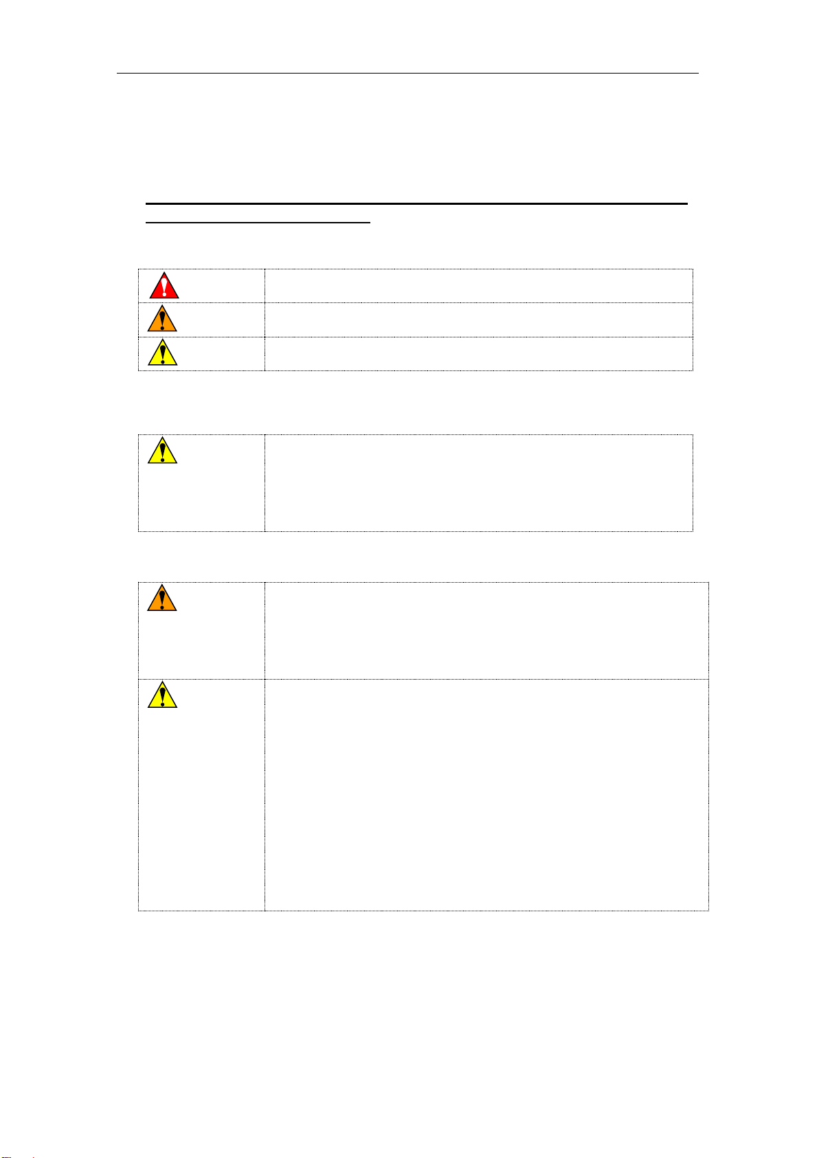
1.1.1.Meanings and descriptions of symbols
In the case of mishandling, a user may be killed or suffer a
serious injury immediately.
In the case of mishandling, a user may be killed or suffer a
serious injury.
In the case of mishandling, a user may suffer an injury or material
damage is expected.
*Using this product involves no risk corresponding to "Danger".
1.1.2.Cautions concerning installation
Observe the installation requirements and power
requirements, or a failure may occur.
Install the instrument on a horizontal working table with
sufficient strength, or a slight injury or a failure caused by a
fall or a drop may result.
1.1.3.Cautions concerning handling
Before using a reagent, procure and administer the safety data
sheet (SDS).
When using a reagent, wear protective equipment and carry out
ventilation sufficiently. Reagents to be used for the instrument
include acute toxic and corrosive substances.
Do not disassemble or modify the instrument without
permission, or a failure may result.
Read this document carefully before using the instrument, or a
failure caused by an operational mistake may result.
Observe the range of the specification, or a failure may result.
Do not operate the instrument with a wet hand.
Cut off the power supply before carrying out maintenance work,
or a failure caused by a short circuit may result.
Dispose of effluent appropriately after using the instrument.
Do not touch any driving unit intentionally. An injury is not likely
to occur because the speed and torque are low, but a failure of
the instrument may result.
Danger
Warning
Caution
Caution
Warning
Caution

Instruction Manual MA-3000+RD-5+SC-5 NIC-TD-0000015-05
2
1.2. Overview
This system is connected to MA-3000, and performs the reducing vaporization
method automatically. It consists of the pump unit which is mounted on MA-3000
rear side, and the auto sample changer SC-5, and the reagent dispenser RD-5.
Auto sample changer SC-5 is available to set 30 samples.Any sample positions
can be random-accessed. Moreover additional samples can be loaded during the
measurement. It also has the function of bubbler cleaning after measuring.
The reagent dispensing unit RD-5 adds of sulfuric acid and reducing reagent, and
feeds distilled water for washing bubbler.
Instruction Manual MA-3000+RD-5+SC-5 NIC-TD-0000015-05
3
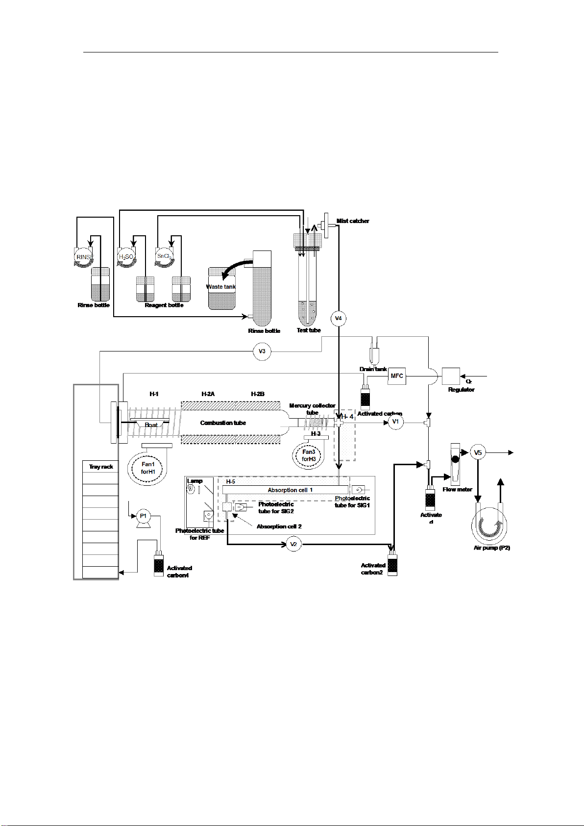
1.3. Measurement principle
Set unspecified samples pretreated by wet degradation etc. Mercury in pretreated
sample has become bivalent mercury ion (Hg2+). 0-valency mercury (Hg0) comes out
when reducing agent (SnCl2) is added and followed by being bubbled. 0-valency
mercury (Hg0) introduces to cell by clean air, and amount of mercury is calculated by
a cold vapor atomic absorption method.
Flow Diagram

Instruction Manual MA-3000+RD-5+SC-5 NIC-TD-0000015-05
4
1.4. External appearance of instrument
1.4.1.RD-5
1.4.1.1. Front
No.
Name
Description
1
Reagent dispenser main
unit
Houses tube pumps for reagent dispensing.
2
Stand (fixed portion)
Fixes the reagent dispenser.
3
Stand (movable portion)
Can be slid to mount the SC-5.
2
1
3
3

Instruction Manual MA-3000+RD-5+SC-5 NIC-TD-0000015-05
5
1.4.1.2. Right side
No.
Name
Description
1
Reagent pump (P1)
Used mainly for the reagent sulfuric acid (1+1).
2
Reagent pump (P2)
Used mainly for the reagent 10% stannous chloride
(II) solution.
3
Reagent pump (P3)
Reserved
1.4.1.3. Rear
No.
Name
Description
1
RD-5 connector
This is a connector for connection to the MA-3000.
2
SC-5 fixing hole
This is a hole to fix the SC-5 to the stand using the
supplied knurled screw.
2
1
3
3
2
1
Instruction Manual MA-3000+RD-5+SC-5 NIC-TD-0000015-05
6
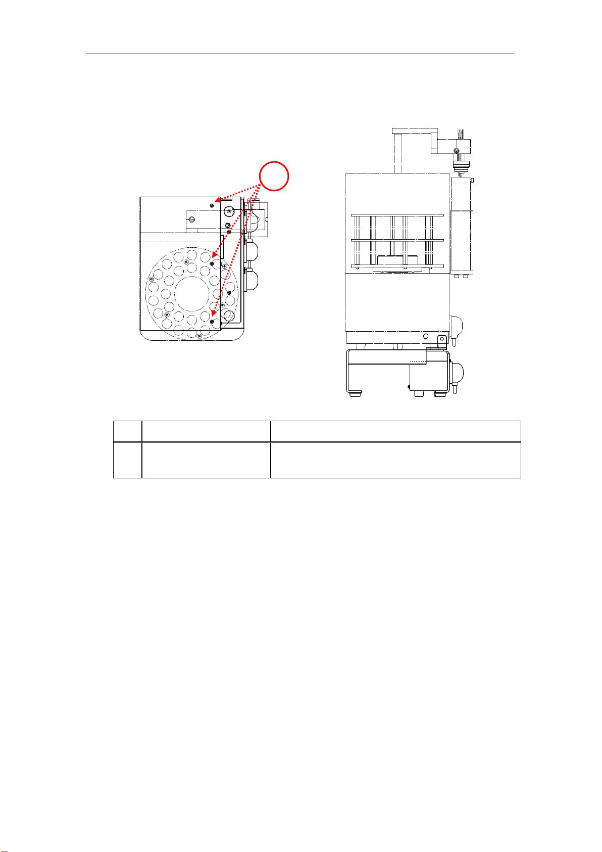
1.4.1.4. Upper face
No.
Name
Description
1
Fixing screws
Fix the movable portion of the stand to the fixed
portion. (3 places)
1
Positions of fixing screws when SC-5 is installed
Instruction Manual MA-3000+RD-5+SC-5 NIC-TD-0000015-05
7
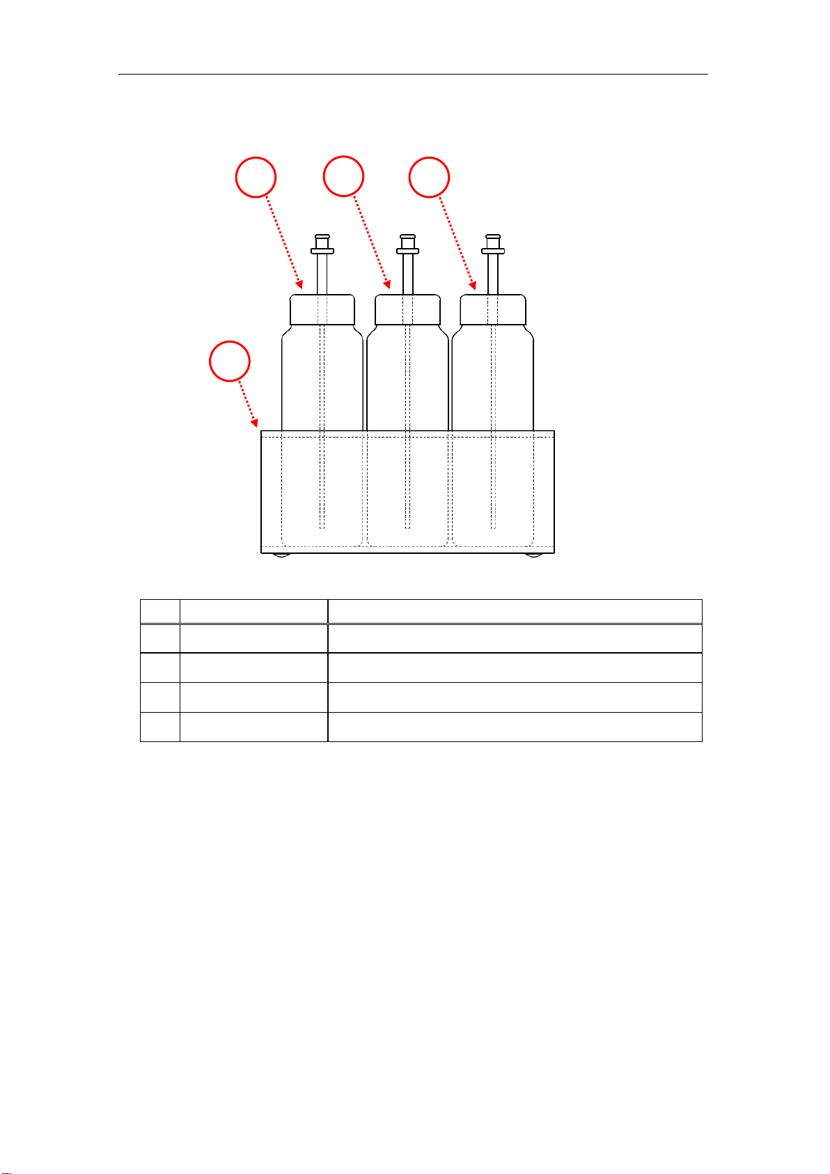
1.4.1.5. Reagent bottles and reagent bottle stand
No.
Name
Description
1
Reagent Bottle 1
This is the reagent container for the reagent pump P1.
2
Reagent Bottle 2
This is the reagent container for the reagent pump P2.
3
Reagent Bottle 3
This is the reagent container for the reagent pump P3.
4
Reagent stand
Three kinds of reagent bottles are set.
1
2
3
4

Instruction Manual MA-3000+RD-5+SC-5 NIC-TD-0000015-05
8
1.4.2.SC-5
1.4.2.1. Front
No.
Name
Description
1
Table
This is a turntable on which to set sample
containers.
2
Table holder
This is a holder for the positioning of the table.
3
Cap unit
Seals a sample container.
4
Arm
Holds the cap unit, moves vertically and turns.
5
Power pilot lamp
The blue lamp lights when the power is turned on.
1
2
3
4
5

Instruction Manual MA-3000+RD-5+SC-5 NIC-TD-0000015-05
9
1.4.2.2. Right side
No.
Name
Description
1
Power switch
This turns on and off the instrument.
2
Rinse pump
This is a pump to supply pure water for cleaning.
3
Washing tank
The bubbler is washed using pure water supplied
from the rinse pump.
3
2
1
Rinse pump outlet side
Rinse pump inlet side
Instruction Manual MA-3000+RD-5+SC-5 NIC-TD-0000015-05
10
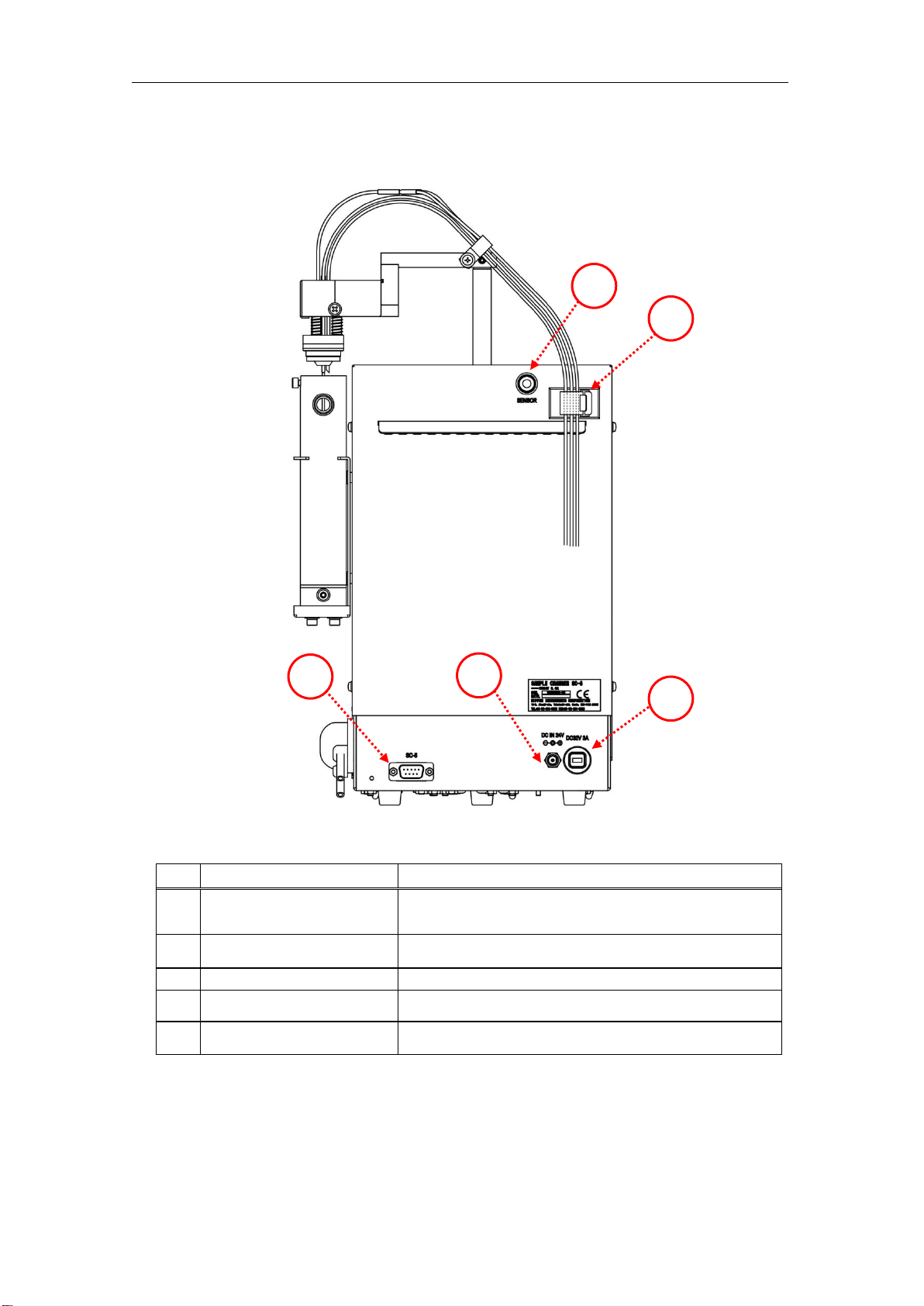
1.4.2.3. Rear
No.
Name
Description
1
Communication
connector
To be connected to the main detector using the
supplied communication cable.
2
DC jack
The supplied AC adapter is connected.
3
Circuit protector
This is an overcurrent protection device.
4
Seal sensor connector
The seal sensor of the cap unit is connected.
5
Clamp
Tubes of the cap unit are passed.
3
2
1
5
4

Instruction Manual MA-3000+RD-5+SC-5 NIC-TD-0000015-05
11
1.4.2.4. Upper face
No.
Name
Description
1
Table shaft
This is a rotation driving shaft. The table holder is
attached.
2
Shaft cap
Covers an unused shaft to protect the inside.
1
2
Table shaft for standard
capacity (5 mL)
Table shaft for optional
large capacity
Instruction Manual MA-3000+RD-5+SC-5 NIC-TD-0000015-05
12
2. Installation of instruments
Observe the installation requirements, or a failure may occur.
Install the instrument on a horizontal working table with
sufficient strength, or a slight injury or a failure caused by a
fall or a drop may result.
Do not operate the instrument before installation and
connection are all completed.
Check that each tube is not wet or dirty.
Do not operate the instrument before the connection of each
tube is completed.
Make cable tie surely in order to prevent piping
disconnection. It may cause leakage or disconnection.
Be careful not to damage fittings.
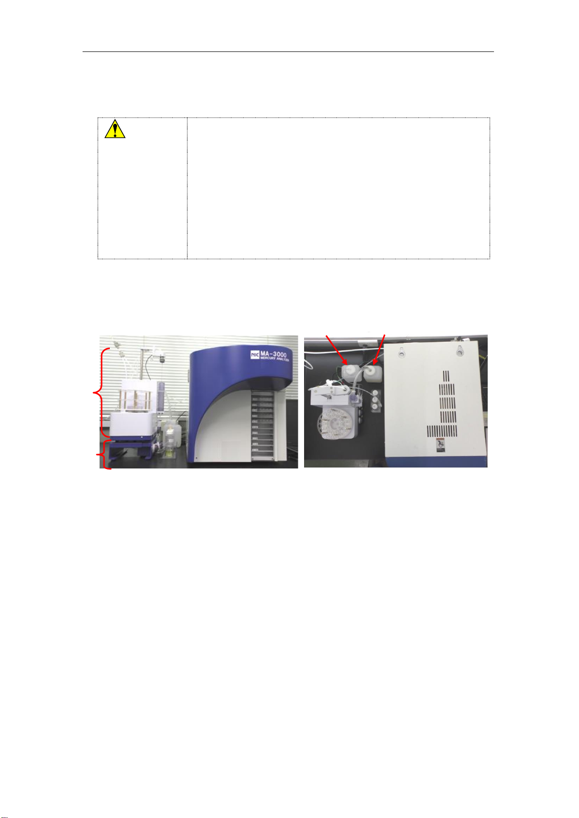
The location of each instruments is as shown in the figure below. Please install according
to the following procedure.
Caution
Pure water
tank
Effluent tank
RD-5
SC-5

Instruction Manual MA-3000+RD-5+SC-5 NIC-TD-0000015-05
13
2.1. Installation of RD-5 and SC-5
1) Adjust the width of the stand of the RD-5 for the SC-5.
2) Put the RD-5 on the left side of MA-3000.
3) Install the SC-5 on the stand of the RD-5, and then attach the supplied
knurled screw to the fixing hole in the rear to fix the SC-5 to the stand of the
RD-5.
Positions of fixing screws when SC-5 is installed
Rear
Instruction Manual MA-3000+RD-5+SC-5 NIC-TD-0000015-05
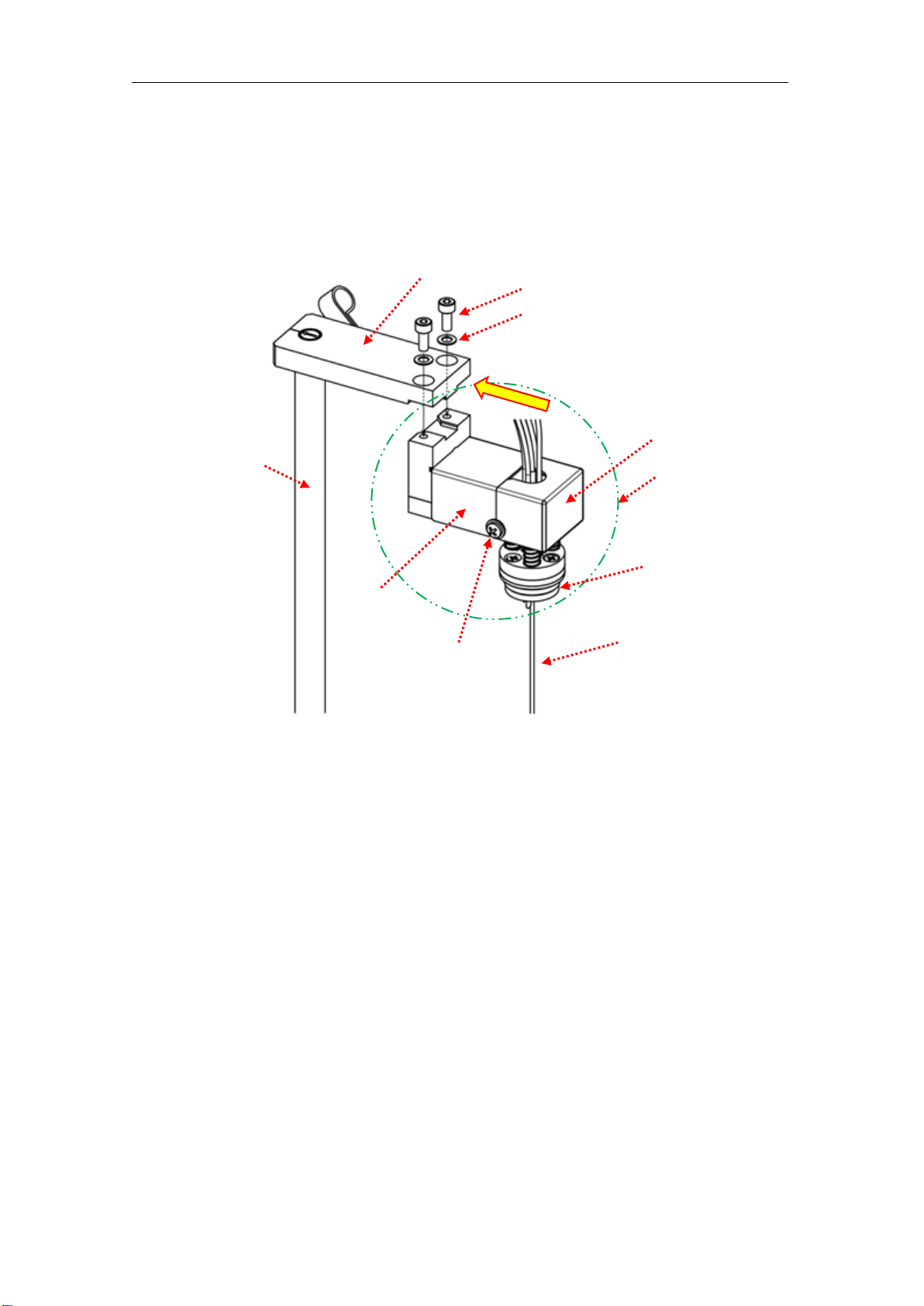
14
2.2. Fixing of cap unit
1) Attach the cap unit to the arm using two M4 hexagon socket head cap screws
and two washers.
When attaching, push in the direction of the arm rotation axis (direction of the
arrow), and determine the position.
Arm
Hexagon socket head cap screw
Washer
Cap unit
Arm cover F
Seal packing
Bubbler
Screw fixing cover
(Also on opposite side)
Arm cover R
Arm rotation axis
Direction for pushing cap unit

Instruction Manual MA-3000+RD-5+SC-5 NIC-TD-0000015-05
15
2.3. Connection on rear side
1) Connect the supplied SCIF cable to the communication connector, and
connect the other side to the MA-3000.
2) Connect the AC adapter output plug in the accessories to the DC jack.
Connect the AC adapter to the outlet with the ground.
3) Connect the seal sensor of the cap unit to the seal sensor connector.
4) Pass the cap tubes and the cable of the seal sensor through the nylon clamp,
and fix it to the arm using an M4 screw. In the case of the optional large cap,
pass only the cable of the seal sensor.
5) Pass the cap tubes through the clamp.
Nylon clamp
Reaction tube
Seal sensor cable
Clamp
AC adapter
output plug
Communication cable
M4 screw
2)
1)
3)
4)
5)

Instruction Manual MA-3000+RD-5+SC-5 NIC-TD-0000015-05
16
6) Connect the reaction tube (with mist catcher of the cap on SC-5) to the joint of V4
valve IN of MA-3 rear.
7) Connect the instrument to the MA-3000 using the supplied RDIF cable.
V4 valve
Reaction tube
1) SC-5 - MA-3000
7) RD-5 - MA-3000
Table of contents
Other Nippon Measuring Instrument manuals

Nippon
Nippon Mercury/PE-1 User manual

Nippon
Nippon EMP-3 User manual

Nippon
Nippon Hi-Lutor User manual

Nippon
Nippon MA-3 Solo User manual

Nippon
Nippon RA-4500 User manual

Nippon
Nippon MA-3000 User manual

Nippon
Nippon WA-5A User manual

Nippon
Nippon EMP-3 User manual

Nippon
Nippon MA-3000 User manual

Nippon
Nippon MA-3 Solo User manual


